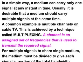
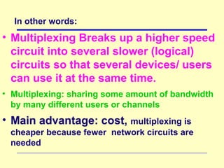
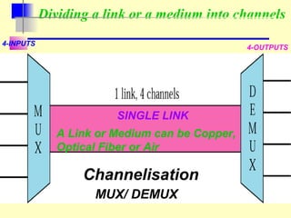
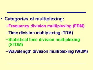
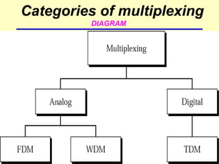
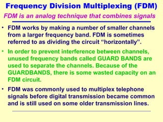
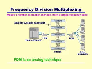
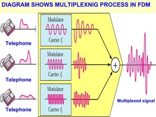
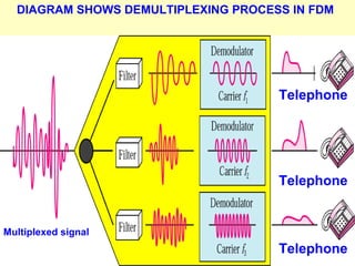
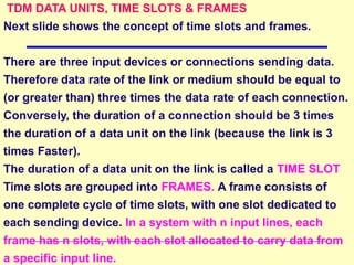
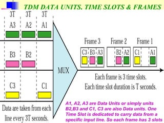
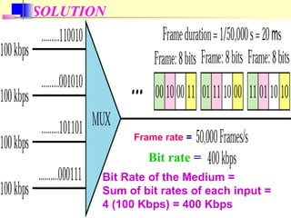
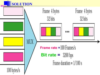
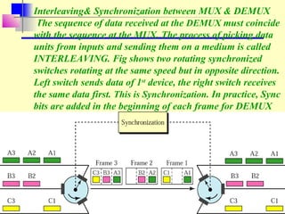
MULTIPLEXING
In a simple way, a medium can carry only one
signal at any instant in time. Usually, it is
desirable that a medium should carry
multiple signals at the same time.
A common example is multiple channels on
cable TV. This is achieved by a technique
called MULTIPLEXING. A channel is an
assigned set of frequencies that is used to
transmit the required signal.
For multiple signals to share single medium,
the medium must be divided to give each
In other words:
• Multiplexing Breaks up a higher speed
circuit into several slower (logical)
circuits so that several devices/ users
can use it at the same time.
• Multiplexing: sharing some amount of bandwidth
by many different users or channels
• Main advantage: cost, multiplexing is
cheaper because fewer network circuits are
needed
Dividing a link or a medium into channels
4-INPUTS
Channelisation
MUX/ DEMUX
4-OUTPUTS
SINGLE LINK
A Link or Medium can be Copper,
Optical Fiber or Air
• Categories of multiplexing:
–Frequency division multiplexing (FDM)
–Time division multiplexing (TDM)
–Statistical time division multiplexing
(STDM)
–Wavelength division multiplexing (WDM)
Categories of multiplexing
DIAGRAM
Frequency Division Multiplexing (FDM)
• FDM works by making a number of smaller channels
from a larger frequency band. FDM is sometimes
referred to as dividing the circuit “horizontally”.
• In order to prevent interference between channels,
unused frequency bands called GUARD BANDS are
used to separate the channels. Because of the
GUARDBANDS, there is some wasted capacity on an
FDM circuit.
• FDM was commonly used to multiplex telephone
signals before digital transmission became common
and is still used on some older transmission lines.
FDM is an analog technique that combines signals
ExampleExample
Assume that a voice channel occupies a
bandwidth of 4 KHz. We need to combine
three voice channels into a link with a
bandwidth of 12 KHz, from 20 to 32 KHz.
Show the configuration using the frequency
domain without the use of guard bands.
SolutionSolution
Shift (modulate) each of the three voice
channels to a different bandwidth, as
shown in the next slide.
Solution:
KHz
KHz
KHz
KHz
Frequency Division Multiplexing
Makes a number of smaller channels from a larger frequency band
3000 Hz available bandwidth
circuit
FDMFDM
Four
terminals
Host computer
FDM is an analog technique
ExampleExample
Five channels, each with a 100-KHz bandwidth,
are to be multiplexed together. What is the
minimum bandwidth of the link if there is a need
for a guard band of 10 KHz between the channels
to prevent interference?
SolutionSolution
For five channels, we need at least four guard
bands. This means that the required
bandwidth is at least
5 x 100 + 4 x 10 = 540 KHz,
as shown in the next slide
SOLUTION
Telephone
Multiplexed signal
Telephone
Telephone
DIAGRAM SHOWS MULTIPLEXNIG PROCESS IN FDM
DIAGRAM SHOWS DEMULTIPLEXING PROCESS IN FDM
Multiplexed signal
Telephone
Telephone
Telephone
ExampleExample
An analog Cellular Service Provider uses two
bands. The 1st band ( 824 to 849 MHz) is used
for sending; and 2nd
band (869 to 894 MHz) is
used for receiving. Each user has a bandwidth of
30 KHz in each direction. The 3-KHz voice is
modulated using FM, creating 30 KHz of
modulated signal. How many people can use their
cellular phones simultaneously?
SolutionSolution
Each band is 25 MHz. If we divide 25 MHz into 30
KHz, (25 MHz/30 KHz) we get 833.33. Practically,
ANALOG HIERARICHY IN FDM
To increase efficiency, Telephone HIGHER-
BANDWIDTH LINES. Such an arrangement is
called HIERARICHY. companies multiplex signals
from LOWER-BANDWITH LINES onto
The HIERARICHY used by AT&T is made up of
GROUPS, SUPERGROUPS, MASTERR GROUPS
and JUMBO GROUPS as shown in the next slide
FDIAGRAM: FDM/Analog hierarchy (AT&T)
Time Division Multiplexing (TDM)
• TDM allows multiple channels to be used by
allowing the channels to send data by taking
turns. TDM is sometimes referred to as dividing
the circuit “vertically”
• With TDM, Time on the circuit is shared equally
with each circuit getting a specified time slot,
whether or not it has any data to send.
• TDM is more efficient than FDM, since TDM
doesn’t use guardbands, so the entire capacity
can be divided up between the data channels.
Time Division Multiplexing
Dividing the circuit “vertically”
• Allows multiple
channels to send
data by taking turns
4 terminals sharing a circuit,
with each terminal sending
single or multiple characters
at a time. 1 character = 8 bits
Diagram in the next slide gives further
explanation of the TDM technique.
4 computers are sending signals to the TDM
multiplexer. The data flow of each computer is
divided into units and the link combines one data
unit of each connection to make a frame. The size of
one unit can be 1 bit or several bits.
In the diagram, portions of signals 1,2,3, and 4
occupy the link sequentially.
TDM
TDM DATA UNITS, TIME SLOTS & FRAMES
Next slide shows the concept of time slots and frames.
There are three input devices or connections sending data.
Therefore data rate of the link or medium should be equal to
(or greater than) three times the data rate of each connection.
Conversely, the duration of a connection should be 3 times
the duration of a data unit on the link (because the link is 3
times Faster).
The duration of a data unit on the link is called a TIME SLOT
Time slots are grouped into FRAMES. A frame consists of
one complete cycle of time slots, with one slot dedicated to
each sending device. In a system with n input lines, each
frame has n slots, with each slot allocated to carry data from
a specific input line.
TDM DATA UNITS, TIME SLOTS & FRAMES
A1, A2, A3 are Data Units or simply units
B2,B3 and C1, C3 are also Data units. One
Time Slot is dedicated to carry data from a
specific input line. So each frame has 3 slots
REMEMBERREMEMBER
In a TDM, the data rateIn a TDM, the data rate
of the link is n timesof the link is n times
faster, and the unitfaster, and the unit
duration is n timesduration is n times
shorter.shorter.
ExampleExample
Four 1-Kbps connections are multiplexed together. A data
unit is 1 bit. Find (1) the duration of 1 bit before
multiplexing, (2) the transmission rate of the link, (3) the
duration of a time slot, and (4) the duration of a frame?
SolutionSolution
Answers as follows:
1. The duration of 1 bit is 1/1 Kbps, or 0.001 s (1 ms).
2. The rate of the link is 4 Kbps.
3. The duration of each time slot 1/4 ms or 250 µs.
4. The duration of a frame 1 ms.
EXAMPLE
• A multiplexer combines four 100-Kbps
channels using a time slot of 2 bits.
• Show the output with four arbitrary inputs.
What is the frame rate? What is the frame
duration? What is the bit rate? What is the
bit duration?
See next slide for solution
SOLUTION
Bit rate =
Frame rate =
Bit Rate of the Medium =
Sum of bit rates of each input =
4 (100 Kbps) = 400 Kbps
ExampleExample
Four channels are multiplexed using TDM. If
each channel sends 100 bytes/s and we
multiplex 1 byte per channel, show the frame
traveling on the link, the size of the frame, the
duration of a frame, the frame rate, and the
bit rate for the link.
SolutionSolution
See next slide
SOLUTION
Frame rate =
Bit rate =
Interleaving& Synchronization between MUX & DEMUX
The sequence of data received at the DEMUX must coincide
with the sequence at the MUX. The process of picking data
units from inputs and sending them on a medium is called
INTERLEAVING. Fig shows two rotating synchronized
switches rotating at the same speed but in opposite direction.
Left switch sends data of 1st
device, the right switch receives
the same data first. This is Synchronization. In practice, Sync
bits are added in the beginning of each frame for DEMUX

Telecom lect 4

  • 1.
  • 2.
    In a simpleway, a medium can carry only one signal at any instant in time. Usually, it is desirable that a medium should carry multiple signals at the same time. A common example is multiple channels on cable TV. This is achieved by a technique called MULTIPLEXING. A channel is an assigned set of frequencies that is used to transmit the required signal. For multiple signals to share single medium, the medium must be divided to give each
  • 3.
    In other words: •Multiplexing Breaks up a higher speed circuit into several slower (logical) circuits so that several devices/ users can use it at the same time. • Multiplexing: sharing some amount of bandwidth by many different users or channels • Main advantage: cost, multiplexing is cheaper because fewer network circuits are needed
  • 4.
    Dividing a linkor a medium into channels 4-INPUTS Channelisation MUX/ DEMUX 4-OUTPUTS SINGLE LINK A Link or Medium can be Copper, Optical Fiber or Air
  • 5.
    • Categories ofmultiplexing: –Frequency division multiplexing (FDM) –Time division multiplexing (TDM) –Statistical time division multiplexing (STDM) –Wavelength division multiplexing (WDM)
  • 6.
  • 7.
    Frequency Division Multiplexing(FDM) • FDM works by making a number of smaller channels from a larger frequency band. FDM is sometimes referred to as dividing the circuit “horizontally”. • In order to prevent interference between channels, unused frequency bands called GUARD BANDS are used to separate the channels. Because of the GUARDBANDS, there is some wasted capacity on an FDM circuit. • FDM was commonly used to multiplex telephone signals before digital transmission became common and is still used on some older transmission lines. FDM is an analog technique that combines signals
  • 8.
    ExampleExample Assume that avoice channel occupies a bandwidth of 4 KHz. We need to combine three voice channels into a link with a bandwidth of 12 KHz, from 20 to 32 KHz. Show the configuration using the frequency domain without the use of guard bands. SolutionSolution Shift (modulate) each of the three voice channels to a different bandwidth, as shown in the next slide.
  • 9.
  • 10.
    Frequency Division Multiplexing Makesa number of smaller channels from a larger frequency band 3000 Hz available bandwidth circuit FDMFDM Four terminals Host computer FDM is an analog technique
  • 11.
    ExampleExample Five channels, eachwith a 100-KHz bandwidth, are to be multiplexed together. What is the minimum bandwidth of the link if there is a need for a guard band of 10 KHz between the channels to prevent interference? SolutionSolution For five channels, we need at least four guard bands. This means that the required bandwidth is at least 5 x 100 + 4 x 10 = 540 KHz, as shown in the next slide
  • 12.
  • 13.
  • 14.
    DIAGRAM SHOWS DEMULTIPLEXINGPROCESS IN FDM Multiplexed signal Telephone Telephone Telephone
  • 15.
    ExampleExample An analog CellularService Provider uses two bands. The 1st band ( 824 to 849 MHz) is used for sending; and 2nd band (869 to 894 MHz) is used for receiving. Each user has a bandwidth of 30 KHz in each direction. The 3-KHz voice is modulated using FM, creating 30 KHz of modulated signal. How many people can use their cellular phones simultaneously? SolutionSolution Each band is 25 MHz. If we divide 25 MHz into 30 KHz, (25 MHz/30 KHz) we get 833.33. Practically,
  • 16.
    ANALOG HIERARICHY INFDM To increase efficiency, Telephone HIGHER- BANDWIDTH LINES. Such an arrangement is called HIERARICHY. companies multiplex signals from LOWER-BANDWITH LINES onto The HIERARICHY used by AT&T is made up of GROUPS, SUPERGROUPS, MASTERR GROUPS and JUMBO GROUPS as shown in the next slide
  • 17.
  • 18.
    Time Division Multiplexing(TDM) • TDM allows multiple channels to be used by allowing the channels to send data by taking turns. TDM is sometimes referred to as dividing the circuit “vertically” • With TDM, Time on the circuit is shared equally with each circuit getting a specified time slot, whether or not it has any data to send. • TDM is more efficient than FDM, since TDM doesn’t use guardbands, so the entire capacity can be divided up between the data channels.
  • 19.
    Time Division Multiplexing Dividingthe circuit “vertically” • Allows multiple channels to send data by taking turns 4 terminals sharing a circuit, with each terminal sending single or multiple characters at a time. 1 character = 8 bits
  • 20.
    Diagram in thenext slide gives further explanation of the TDM technique. 4 computers are sending signals to the TDM multiplexer. The data flow of each computer is divided into units and the link combines one data unit of each connection to make a frame. The size of one unit can be 1 bit or several bits. In the diagram, portions of signals 1,2,3, and 4 occupy the link sequentially.
  • 21.
  • 22.
    TDM DATA UNITS,TIME SLOTS & FRAMES Next slide shows the concept of time slots and frames. There are three input devices or connections sending data. Therefore data rate of the link or medium should be equal to (or greater than) three times the data rate of each connection. Conversely, the duration of a connection should be 3 times the duration of a data unit on the link (because the link is 3 times Faster). The duration of a data unit on the link is called a TIME SLOT Time slots are grouped into FRAMES. A frame consists of one complete cycle of time slots, with one slot dedicated to each sending device. In a system with n input lines, each frame has n slots, with each slot allocated to carry data from a specific input line.
  • 23.
    TDM DATA UNITS,TIME SLOTS & FRAMES A1, A2, A3 are Data Units or simply units B2,B3 and C1, C3 are also Data units. One Time Slot is dedicated to carry data from a specific input line. So each frame has 3 slots
  • 24.
    REMEMBERREMEMBER In a TDM,the data rateIn a TDM, the data rate of the link is n timesof the link is n times faster, and the unitfaster, and the unit duration is n timesduration is n times shorter.shorter.
  • 25.
    ExampleExample Four 1-Kbps connectionsare multiplexed together. A data unit is 1 bit. Find (1) the duration of 1 bit before multiplexing, (2) the transmission rate of the link, (3) the duration of a time slot, and (4) the duration of a frame? SolutionSolution Answers as follows: 1. The duration of 1 bit is 1/1 Kbps, or 0.001 s (1 ms). 2. The rate of the link is 4 Kbps. 3. The duration of each time slot 1/4 ms or 250 µs. 4. The duration of a frame 1 ms.
  • 26.
    EXAMPLE • A multiplexercombines four 100-Kbps channels using a time slot of 2 bits. • Show the output with four arbitrary inputs. What is the frame rate? What is the frame duration? What is the bit rate? What is the bit duration? See next slide for solution
  • 27.
    SOLUTION Bit rate = Framerate = Bit Rate of the Medium = Sum of bit rates of each input = 4 (100 Kbps) = 400 Kbps
  • 28.
    ExampleExample Four channels aremultiplexed using TDM. If each channel sends 100 bytes/s and we multiplex 1 byte per channel, show the frame traveling on the link, the size of the frame, the duration of a frame, the frame rate, and the bit rate for the link. SolutionSolution See next slide
  • 29.
  • 30.
    Interleaving& Synchronization betweenMUX & DEMUX The sequence of data received at the DEMUX must coincide with the sequence at the MUX. The process of picking data units from inputs and sending them on a medium is called INTERLEAVING. Fig shows two rotating synchronized switches rotating at the same speed but in opposite direction. Left switch sends data of 1st device, the right switch receives the same data first. This is Synchronization. In practice, Sync bits are added in the beginning of each frame for DEMUX