Downloaded 248 times


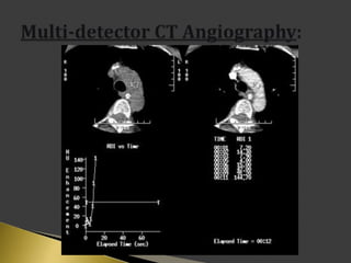


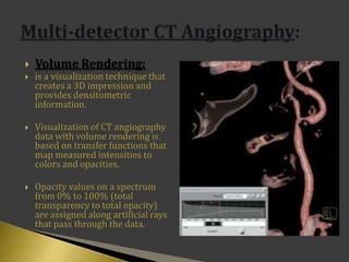


This document discusses techniques for computed tomography (CT) angiography. It covers advances in CT technology that have improved angiography, including faster scan speeds and thinner slices. Optimal CT angiography depends on scan technique factors like protocol and contrast injection, as well as image post-processing techniques. Newer multi-detector CT machines allow covering volumes more quickly and with higher resolution. Methods like multi-planar reformation and volume rendering help visualize vascular structures from CT image data.


