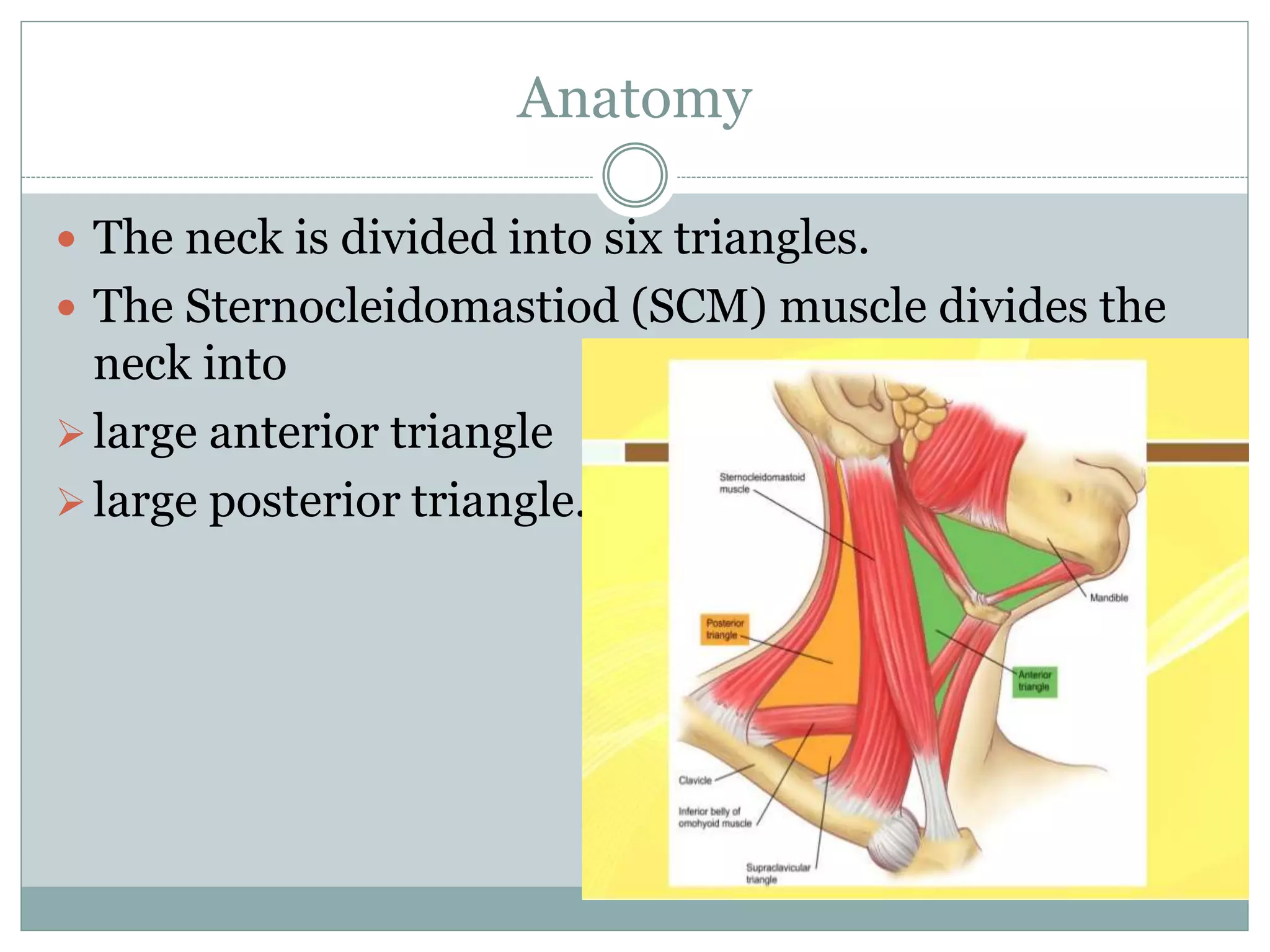
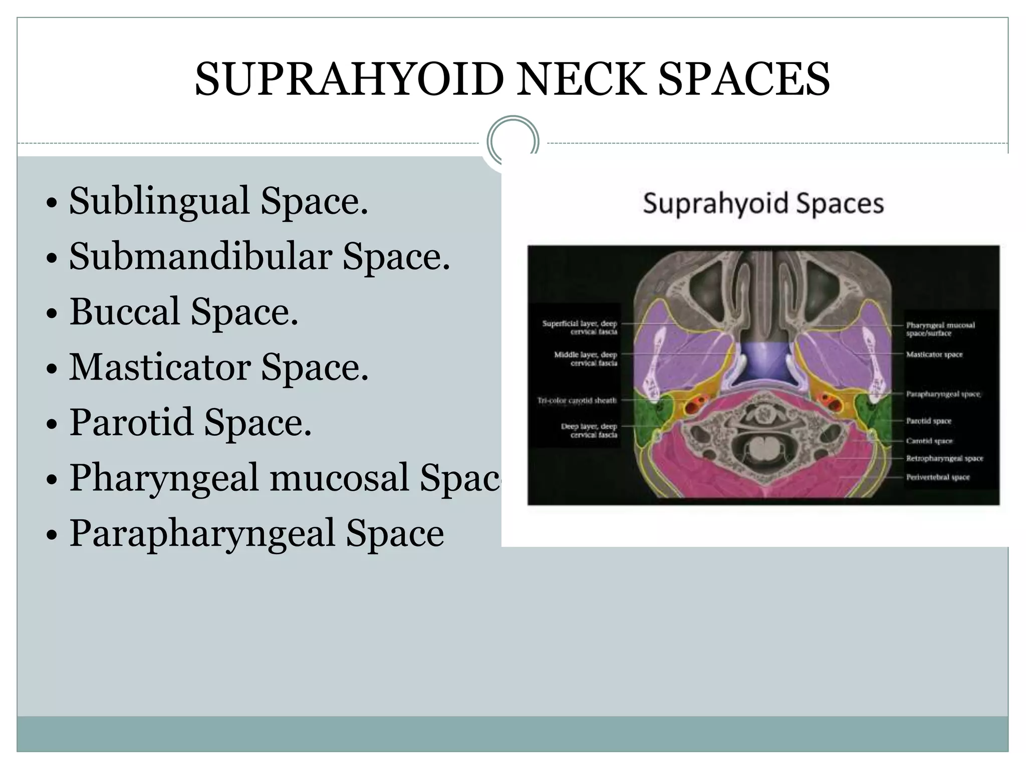
SABITA MANDAL
ROLL NO. 3
B.SC MIT 3R D YEAR
NAMS, BIR HOSPITAL
CT procedure of neck
Contents
 Anatomy
 Modalities for imaging neck
 Indications
 contraindications
 Imaging techniques
 References
Anatomy
Anatomy
Anatomy
 The neck is the part of the human body, that separates the head from
the torso or is the part of the human body that attaches the head to the
rest of the body.
 It contains blood vessels and nerves that supply structures in the head
to the body.
 Neck extends from anteriorly located cervix to the posteriorly located
nucha.
 Nucha consists of vertebral column and its associated musculature.
 Cervix (simply neck is a cylinder of soft tissue whose superior extent
is line connecting the occiput and tip of the chin and its inferior extent
parallels the course of the first rib at the thoracic inlet.
Anatomy
 For imaging purposes, the boundaries of the neck are
 mandible and the mylohyoid muscles- anterosuperiorly
 the base of the skull- posterosuperiorly
 the scapulae- posteroinferiorly
 the thoracic inlet- centrally in the inferior aspect.
Muscles of neck
 Superficial muscles
 Platysma muscle
 Sternocleidomastiod muscle
 trapezius muscle
 Deep muscles
 Suboccipital muscles
 Suprahyoid muscles
 Infrahyoid muscles
 scalene muscles
Anatomy
Anatomy
 The neck is divided into six triangles.
 The Sternocleidomastiod (SCM) muscle divides the
neck into
large anterior triangle
large posterior triangle.
The anterior triangle is further divided by both bellies of the digastric muscle and the superior belly of
omohyoid muscle into four triangles :
Submental triangle
Submandibular
triangle
Carotid triangle Muscular triangle
Boundaries Superiorly: the chin
Laterally: the two anterior
bellies of the diagastric
muscle
Medially: the mid-line
The bellies of the
diagastric muscles and
the mandible
Superiorly: the posterior
belly of the diagastric
muscle
Laterally: the anterior
border of the
Sternocleidomastiod
muscle
Medially: the superior
belly of the omohyoid
muscle
The superior belly of the
omohyoid muscle and
the sternohyoid muscle
Contents The submental lymph nodes The Submandibular
salivary glands and
Submandibular lymph
nodes
The carotid artery, the
internal jugular vein,
the vagus nerve and the
internal and external
laryngeal nerves
The deep structures
including the larynx,
trachea, thyroid and the
oesophagus
The posterior triangle is further divided by the inferior belly of the omohyoid muscle into two triangles:
Occipital triangle
the larger subdivision of the posterior
triangle
Supraclavicular triangle
the smaller subdivision of the
posterior triangle
Boundaries Anteriorly:
the Sternocleidomastoid muscle
Posteriorly: the Trapezius muscle
Inferiorly: the Omohyoid muscle
Anteriorly: the posterior border of
the Sternocleidomastoid
Superiorly: the inferior belly of the
Omohyoid muscle
Inferiorly: the clavicle
Contents Most lumps arising from the posterior triangle are due to enlarged occipital or
Supraclavicular lymph nodes.
Other important structures include the subclavian artery, the external jugular vein, the
accessory nerve, the phrenic nerve and parts of the brachial plexus.
Spaces of neck
 The ‘neck space’ concept is a commonly used
method in radiology in organizing the neck and
establishing appropriate differential diagnosis for
pathology discovered within a specific space of the
neck.
 These spaces may limit to some degree the spread
of most infections and some tumors.
Spaces of neck
 These spaces are described in relation to the hyoid
bone.
• Suprahyoid Spaces.
• Infrahyoid Spaces.
• Spaces extending up to the entire length of the neck
SUPRAHYOID NECK SPACES
• Sublingual Space.
• Submandibular Space.
• Buccal Space.
• Masticator Space.
• Parotid Space.
• Pharyngeal mucosal Space.
• Parapharyngeal Space
Anatomy
Anatomy of neck
INFRAHYOID NECK SPACES
• Visceral Space.
• Anterior cervical Space.
• Posterior cervical Space.
Anatomy
Anatomy
SPACES COMMON TO BOTH
• Carotid Space.
• Retropharyngeal Space.
• Prevertebral Space.
• Danger Space.
Neck spaces
Anatomy
Nodes of neck
Cervical nodes are classified into seven groups, each designated by
a
roman numeral as follows:
Level I: Submandibular and submental lymph nodes.
Level LI: Internal jugular chain from the skull base to the
level of the carotid bifurcation.
Level 111: Internal jugular chain from the level of the carotid
bifurcation to the level of the intersection of the chain with the
omohyoid muscle.
Level IV: Infraomohyoid portion of the internal jugular chain.
Level V: Posterior triangle lymph nodes.
Level VI: Nodes related to the thyroid gland.
Level VII: Nodes in the tracheoesophageal groove and superior
mediastinum.
Imaging modalities
 CT
 MRI
 US
 Plain X ray and conventional studies
 Isotope scan
 Angiography
Indications
 Inflammatory, nodal and tumoral diseases including
lymphoma and metastases.
 Thyroid diseases
 Pharyngeal lesions
 Salivary glands pathologies
 Detection /confirmation of lesions
 Follow-ups
 Trauma
Contra-indications
 Hypersensitivity to iodinated contrast media
 Pregnancy(relative)
 Renal diseases
Patient Preparation
 Clear history should be taken along with reports of
previous investigations.
 Pregnancy needs to be ruled out.
 Radiopaque materials should be removed from FOV.
 Proper information and instruction about the
procedure.
 NPO for 4-5 hours prior to procedure for CECT
Patient Preparation
 Blood Creatinine levels should be in its normal limit
(M=0.6 to 1.5,F=0.5-1.2 mg/dl) and Blood urea level
should range between 9 to 42 mg/dl
 Signed informed consent from patient or his/her
close relatives.
 Irritable/uncooperative and Pediatric patients
should be sedated.
 Neck should be in neutral position.
 The patient should be instructed to avoid
swallowing movements.
Routine Neck protocol
Patient positioning
 Head first, supine with arms by the sides of the trunk with
hands tucked under the hips.
 Head rest/support can be applied to restrict the neck
movement.
Topogram position/Landmark
 lateral; level of forehead
Routine Neck protocol
 Mode of scanning
 Helical with single breath-hold technique
 Scan orientation
 Cranio-caudal
 Starting location
 Base of the skull
 End location
 Arch of the aorta
 Cranio-caudal orientation reduces artifacts at the level of the
thoracic inlet caused by the beam-hardening effects of the
contrast agent.
 FOV
 Just fitting the ROI.
Routine Neck protocol
 Gantry tilt
 To make the plane of the scanning parallel to the hard palate or
perpendicular to the plane of larynx.
 Contrast administration
 Intravenous and monophasic
 Volume of contrast
 80-100 ml
 Rate of injection of contrast
 2-3 ml/sec
 Scan delay
 30-40 sec
Routine Neck protocol
Slice thickness in reconstruction
 3-5 mm
Slice interval in reconstruction
 1.5-2.5 mm
Reconstruction algorithm/kernel
 Medium smooth for soft tissue.
 Sharp for cartilage, bone and lung parenchyma in the scan
range.
3D-Reconstructions
 MPR
 MIP
Comments
 Unless contraindicated , IV contrast media is used
when scanning the neck.
 The goals in CT scanning of the neck are to allow
sufficient time after contrast administration for
mucosa , lymph nodes , and pathology tissue to
enhance , yet acquire images while the vasculature
remains opacified .
 Scanning too early after the contrast media injection
could result in certain types of neoclassic and
inflammatory processes going undetected .
Cont…
 However, by delaying scan acquisition , the injected
contrast agent will no longer opacify the vasculature .
 One strategy for addressing these contradictory goals
is a split bolus .
 The total contrast dose is split , often in half .
 The first dose is given and a delay of about 2 minutes
is observed .
 This allows time for structures that are slower to
enhance to be opacified.
Cont…
 This allows time for structures that are slower to
enhance to be opacified.
 The delay is followed by a second bolus containing
the remainder of the contrast ; scanning is initiated
soon after the second injection to more fully opacify
the vessels .
 The split bolus injection technique is also frequently
used for maxillofacial studies in which contrast
media is indicated .
Protocol for Larynx and Hypopharynx
 Over 90% of all masses in the region of hypopharynx
and larynx are squamous cell carcinoma.
 Tumors of hypopharynx most often arises in the
pyriform sinus.
Protocol for Larynx and Hypopharynx
Indications
 Screening for inflammatory or mass/tumoral diseases of the
larynx and hypopharynx.
 Traumatic lesion.
 Preoperative baseline scan
 Post-surgery or post-chemotherapy follow-ups.
Patient positioning
 Head first, supine with arms by the sides of the trunk with
hands tucked under the hips.
 Head rest/support can be applied to restrict the neck
movement.
Protocol for Larynx and Hypopharynx
 Topogram position/Landmark
 lateral; level of forehead
 Mode of scanning
 Helical with single breath-hold technique
 Scan orientation
 Cranio-caudal
 Starting location
 Base of the skull
 End location
 Arch of the aorta
 FOV
 Just fitting the ROI.
Protocol for Larynx and Hypopharynx
 Gantry tilt
 To make the plane of the scanning parallel to the hard palate or
perpendicular to the plane of larynx.
 Contrast administration
 Intravenous , monophasic
 Volume of contrast
 80-100 ml
 Rate of injection of contrast
 2-3 ml/sec
 Scan delay
 30-40 sec
Protocol for Larynx and Hypopharynx
 Slice thickness in reconstruction
 3-5 mm
 Slice interval in reconstruction
 1.5-2.5 mm
 Reconstruction algorithm/kernel
 Medium smooth for soft tissue.
 Sharp for cartilage, bone and lung parenchyma in the scan range.
 3D-Reconstructions
 MPR
 MIP
 Virtual endoscopy
 Dynamic manouvers (in MDCT)
 e phonation (for a better visualization of the laryngeal ventricle)
 modified Valsalva-cheeks puffed with a gradual escape of air
(for a better visualization/dilation of the pyriform sinuses).
Protocol for nasopharynx, oropharynx and
oral cavity
Indication
 Staging of malignant tumors.
 Suspected arrosion of the skull base, the hard palate
or the mandible.
 Parapharyngeal masses, inflammatory processes
such as para or retropharyngeal abscess.
 Detection and differentiation of benign lesions.
Protocol for nasopharynx, oropharynx and oral
cavity
Patient preparation
 Remove dental prosthesis, etc
 Instruct the patient to perform quite breathing and
not to swallow.
Protocol for nasopharynx, oropharynx and oral
cavity
 A. Topogram covering the entire pharynx and neck
 B. Topogram showing two spirals avoiding dental
artifacts (possible with 4 row scanner)
Scan Parameters 16 slice scanner
Scanner settings
Tube voltage (kv) 120
Rotation time (s) 0.75-1
Tube current time product(mAs) 180
Pitch corrected tube current time product
(eff.mAs)
140-230
Collimation (mm) 1.25/1.5
Normal pitch 1-1.3
Recon. – slice increment(mm) 2-3 For recon .- 1
Recon. – slice thickness(mm) 3 For recon .- 1.5-2
Convolution kernel Standard and bone
Scan direction Caudocranial
CM application Yes
Conc. Of CM (mg I / ml) 300
Volume (ml) 100
Inj. Rate (ml/s) 1.5-2.0
Saline chaser (ml/s) No
Delay (s) 55 (fixed)
Cont…
 Regarding bony erosions ct is regarded to be
superior to MRI , but regarding perineural tumor
spread through skull base foramina and/or Dural
infiltration MRI (lateral infiltration of the
Parapharyngeal fat space) is superior to CT.
 Thus a combination of both , CT and MRI , is
necessary.
CT Carotid Angiography
Indications
 Suspected occlusion of the carotid arteries, their aneurisms,
dissections.
 Preoperatively for head /neck tumors to detect the origin of
their feeding vessels for the purpose of ligation.
Patient positioning
 Head first, supine with arms by the sides of the trunk with
hands tucked under the hips.
 Head rest/support can be applied to restrict the neck
movement.
CT Carotid Angiography
 Topogram position/Landmark
 lateral; level of forehead
 Mode of scanning
 Helical with single breath-hold technique
 Scan orientation
 Caudo-Cranial
 Starting location
 Arch of the aorta
 End location
 2-3 cm above the sella
 FOV
 Just fitting the ROI.
CT Carotid Angiography
Gantry tilt
 Nil
Contrast administration
 Intravenous , monophasic
Volume of contrast
 100-120 ml
Rate of injection of contrast
 4-5 ml/sec
Scan delay
 10-15 sec
CT Carotid Angiography
Slice thickness in reconstruction
 1.0-1.5 mm
Slice interval in reconstruction
 0.5-0.75 mm
Reconstruction algorithm/kernel
 smooth
3D-Reconstructions
 MIP
 VRT (preferably after bone subtraction)
Advantages of MRI over CT
• Multiplanar capability
• Lack of ionizing radiation
• Safer contrast agents
• Better imaging of soft tissues of neck
Advantages of CT over MRI
• Superior assessment of osseous integrity
• Shorter examination time
• Wider patient access
• Lower cost
Limitations of CT
 It is an expensive technique.
 Very high density restorations as dental restorations
produce severe artifacts on the CT scan.
 High dose of radiation.
 There is an inherent risk with the use of contrast
media.
References
 CT and MRI protocol- a practical approach, Satish K
Bhargava.
 CT and MRI of whole body, Fifth edition, Johan R.
Hagga.
 Protocols for multislice CT, 2nd edition.
 Internet sources
THANK YOU

CT procedure of neck

  • 1.
    SABITA MANDAL ROLL NO.3 B.SC MIT 3R D YEAR NAMS, BIR HOSPITAL CT procedure of neck
  • 2.
    Contents  Anatomy  Modalitiesfor imaging neck  Indications  contraindications  Imaging techniques  References
  • 3.
  • 4.
  • 5.
    Anatomy  The neckis the part of the human body, that separates the head from the torso or is the part of the human body that attaches the head to the rest of the body.  It contains blood vessels and nerves that supply structures in the head to the body.  Neck extends from anteriorly located cervix to the posteriorly located nucha.  Nucha consists of vertebral column and its associated musculature.  Cervix (simply neck is a cylinder of soft tissue whose superior extent is line connecting the occiput and tip of the chin and its inferior extent parallels the course of the first rib at the thoracic inlet.
  • 6.
    Anatomy  For imagingpurposes, the boundaries of the neck are  mandible and the mylohyoid muscles- anterosuperiorly  the base of the skull- posterosuperiorly  the scapulae- posteroinferiorly  the thoracic inlet- centrally in the inferior aspect.
  • 7.
    Muscles of neck Superficial muscles  Platysma muscle  Sternocleidomastiod muscle  trapezius muscle  Deep muscles  Suboccipital muscles  Suprahyoid muscles  Infrahyoid muscles  scalene muscles
  • 8.
  • 9.
    Anatomy  The neckis divided into six triangles.  The Sternocleidomastiod (SCM) muscle divides the neck into large anterior triangle large posterior triangle.
  • 10.
    The anterior triangleis further divided by both bellies of the digastric muscle and the superior belly of omohyoid muscle into four triangles : Submental triangle Submandibular triangle Carotid triangle Muscular triangle Boundaries Superiorly: the chin Laterally: the two anterior bellies of the diagastric muscle Medially: the mid-line The bellies of the diagastric muscles and the mandible Superiorly: the posterior belly of the diagastric muscle Laterally: the anterior border of the Sternocleidomastiod muscle Medially: the superior belly of the omohyoid muscle The superior belly of the omohyoid muscle and the sternohyoid muscle Contents The submental lymph nodes The Submandibular salivary glands and Submandibular lymph nodes The carotid artery, the internal jugular vein, the vagus nerve and the internal and external laryngeal nerves The deep structures including the larynx, trachea, thyroid and the oesophagus
  • 11.
    The posterior triangleis further divided by the inferior belly of the omohyoid muscle into two triangles: Occipital triangle the larger subdivision of the posterior triangle Supraclavicular triangle the smaller subdivision of the posterior triangle Boundaries Anteriorly: the Sternocleidomastoid muscle Posteriorly: the Trapezius muscle Inferiorly: the Omohyoid muscle Anteriorly: the posterior border of the Sternocleidomastoid Superiorly: the inferior belly of the Omohyoid muscle Inferiorly: the clavicle Contents Most lumps arising from the posterior triangle are due to enlarged occipital or Supraclavicular lymph nodes. Other important structures include the subclavian artery, the external jugular vein, the accessory nerve, the phrenic nerve and parts of the brachial plexus.
  • 13.
    Spaces of neck The ‘neck space’ concept is a commonly used method in radiology in organizing the neck and establishing appropriate differential diagnosis for pathology discovered within a specific space of the neck.  These spaces may limit to some degree the spread of most infections and some tumors.
  • 14.
    Spaces of neck These spaces are described in relation to the hyoid bone. • Suprahyoid Spaces. • Infrahyoid Spaces. • Spaces extending up to the entire length of the neck
  • 15.
    SUPRAHYOID NECK SPACES •Sublingual Space. • Submandibular Space. • Buccal Space. • Masticator Space. • Parotid Space. • Pharyngeal mucosal Space. • Parapharyngeal Space
  • 16.
  • 17.
  • 18.
    INFRAHYOID NECK SPACES •Visceral Space. • Anterior cervical Space. • Posterior cervical Space.
  • 19.
  • 20.
    Anatomy SPACES COMMON TOBOTH • Carotid Space. • Retropharyngeal Space. • Prevertebral Space. • Danger Space.
  • 21.
  • 22.
  • 23.
    Nodes of neck Cervicalnodes are classified into seven groups, each designated by a roman numeral as follows: Level I: Submandibular and submental lymph nodes. Level LI: Internal jugular chain from the skull base to the level of the carotid bifurcation. Level 111: Internal jugular chain from the level of the carotid bifurcation to the level of the intersection of the chain with the omohyoid muscle. Level IV: Infraomohyoid portion of the internal jugular chain. Level V: Posterior triangle lymph nodes. Level VI: Nodes related to the thyroid gland. Level VII: Nodes in the tracheoesophageal groove and superior mediastinum.
  • 26.
    Imaging modalities  CT MRI  US  Plain X ray and conventional studies  Isotope scan  Angiography
  • 27.
    Indications  Inflammatory, nodaland tumoral diseases including lymphoma and metastases.  Thyroid diseases  Pharyngeal lesions  Salivary glands pathologies  Detection /confirmation of lesions  Follow-ups  Trauma
  • 28.
    Contra-indications  Hypersensitivity toiodinated contrast media  Pregnancy(relative)  Renal diseases
  • 29.
    Patient Preparation  Clearhistory should be taken along with reports of previous investigations.  Pregnancy needs to be ruled out.  Radiopaque materials should be removed from FOV.  Proper information and instruction about the procedure.  NPO for 4-5 hours prior to procedure for CECT
  • 30.
    Patient Preparation  BloodCreatinine levels should be in its normal limit (M=0.6 to 1.5,F=0.5-1.2 mg/dl) and Blood urea level should range between 9 to 42 mg/dl  Signed informed consent from patient or his/her close relatives.  Irritable/uncooperative and Pediatric patients should be sedated.  Neck should be in neutral position.  The patient should be instructed to avoid swallowing movements.
  • 31.
    Routine Neck protocol Patientpositioning  Head first, supine with arms by the sides of the trunk with hands tucked under the hips.  Head rest/support can be applied to restrict the neck movement. Topogram position/Landmark  lateral; level of forehead
  • 32.
    Routine Neck protocol Mode of scanning  Helical with single breath-hold technique  Scan orientation  Cranio-caudal  Starting location  Base of the skull  End location  Arch of the aorta  Cranio-caudal orientation reduces artifacts at the level of the thoracic inlet caused by the beam-hardening effects of the contrast agent.  FOV  Just fitting the ROI.
  • 33.
    Routine Neck protocol Gantry tilt  To make the plane of the scanning parallel to the hard palate or perpendicular to the plane of larynx.  Contrast administration  Intravenous and monophasic  Volume of contrast  80-100 ml  Rate of injection of contrast  2-3 ml/sec  Scan delay  30-40 sec
  • 34.
    Routine Neck protocol Slicethickness in reconstruction  3-5 mm Slice interval in reconstruction  1.5-2.5 mm Reconstruction algorithm/kernel  Medium smooth for soft tissue.  Sharp for cartilage, bone and lung parenchyma in the scan range. 3D-Reconstructions  MPR  MIP
  • 35.
    Comments  Unless contraindicated, IV contrast media is used when scanning the neck.  The goals in CT scanning of the neck are to allow sufficient time after contrast administration for mucosa , lymph nodes , and pathology tissue to enhance , yet acquire images while the vasculature remains opacified .  Scanning too early after the contrast media injection could result in certain types of neoclassic and inflammatory processes going undetected .
  • 36.
    Cont…  However, bydelaying scan acquisition , the injected contrast agent will no longer opacify the vasculature .  One strategy for addressing these contradictory goals is a split bolus .  The total contrast dose is split , often in half .  The first dose is given and a delay of about 2 minutes is observed .  This allows time for structures that are slower to enhance to be opacified.
  • 37.
    Cont…  This allowstime for structures that are slower to enhance to be opacified.  The delay is followed by a second bolus containing the remainder of the contrast ; scanning is initiated soon after the second injection to more fully opacify the vessels .  The split bolus injection technique is also frequently used for maxillofacial studies in which contrast media is indicated .
  • 38.
    Protocol for Larynxand Hypopharynx  Over 90% of all masses in the region of hypopharynx and larynx are squamous cell carcinoma.  Tumors of hypopharynx most often arises in the pyriform sinus.
  • 39.
    Protocol for Larynxand Hypopharynx Indications  Screening for inflammatory or mass/tumoral diseases of the larynx and hypopharynx.  Traumatic lesion.  Preoperative baseline scan  Post-surgery or post-chemotherapy follow-ups. Patient positioning  Head first, supine with arms by the sides of the trunk with hands tucked under the hips.  Head rest/support can be applied to restrict the neck movement.
  • 40.
    Protocol for Larynxand Hypopharynx  Topogram position/Landmark  lateral; level of forehead  Mode of scanning  Helical with single breath-hold technique  Scan orientation  Cranio-caudal  Starting location  Base of the skull  End location  Arch of the aorta  FOV  Just fitting the ROI.
  • 41.
    Protocol for Larynxand Hypopharynx  Gantry tilt  To make the plane of the scanning parallel to the hard palate or perpendicular to the plane of larynx.  Contrast administration  Intravenous , monophasic  Volume of contrast  80-100 ml  Rate of injection of contrast  2-3 ml/sec  Scan delay  30-40 sec
  • 42.
    Protocol for Larynxand Hypopharynx  Slice thickness in reconstruction  3-5 mm  Slice interval in reconstruction  1.5-2.5 mm  Reconstruction algorithm/kernel  Medium smooth for soft tissue.  Sharp for cartilage, bone and lung parenchyma in the scan range.  3D-Reconstructions  MPR  MIP  Virtual endoscopy  Dynamic manouvers (in MDCT)  e phonation (for a better visualization of the laryngeal ventricle)  modified Valsalva-cheeks puffed with a gradual escape of air (for a better visualization/dilation of the pyriform sinuses).
  • 43.
    Protocol for nasopharynx,oropharynx and oral cavity Indication  Staging of malignant tumors.  Suspected arrosion of the skull base, the hard palate or the mandible.  Parapharyngeal masses, inflammatory processes such as para or retropharyngeal abscess.  Detection and differentiation of benign lesions.
  • 44.
    Protocol for nasopharynx,oropharynx and oral cavity Patient preparation  Remove dental prosthesis, etc  Instruct the patient to perform quite breathing and not to swallow.
  • 45.
    Protocol for nasopharynx,oropharynx and oral cavity  A. Topogram covering the entire pharynx and neck  B. Topogram showing two spirals avoiding dental artifacts (possible with 4 row scanner)
  • 46.
    Scan Parameters 16slice scanner Scanner settings Tube voltage (kv) 120 Rotation time (s) 0.75-1 Tube current time product(mAs) 180 Pitch corrected tube current time product (eff.mAs) 140-230 Collimation (mm) 1.25/1.5 Normal pitch 1-1.3 Recon. – slice increment(mm) 2-3 For recon .- 1 Recon. – slice thickness(mm) 3 For recon .- 1.5-2 Convolution kernel Standard and bone Scan direction Caudocranial CM application Yes Conc. Of CM (mg I / ml) 300 Volume (ml) 100 Inj. Rate (ml/s) 1.5-2.0 Saline chaser (ml/s) No Delay (s) 55 (fixed)
  • 47.
    Cont…  Regarding bonyerosions ct is regarded to be superior to MRI , but regarding perineural tumor spread through skull base foramina and/or Dural infiltration MRI (lateral infiltration of the Parapharyngeal fat space) is superior to CT.  Thus a combination of both , CT and MRI , is necessary.
  • 48.
    CT Carotid Angiography Indications Suspected occlusion of the carotid arteries, their aneurisms, dissections.  Preoperatively for head /neck tumors to detect the origin of their feeding vessels for the purpose of ligation. Patient positioning  Head first, supine with arms by the sides of the trunk with hands tucked under the hips.  Head rest/support can be applied to restrict the neck movement.
  • 49.
    CT Carotid Angiography Topogram position/Landmark  lateral; level of forehead  Mode of scanning  Helical with single breath-hold technique  Scan orientation  Caudo-Cranial  Starting location  Arch of the aorta  End location  2-3 cm above the sella  FOV  Just fitting the ROI.
  • 50.
    CT Carotid Angiography Gantrytilt  Nil Contrast administration  Intravenous , monophasic Volume of contrast  100-120 ml Rate of injection of contrast  4-5 ml/sec Scan delay  10-15 sec
  • 51.
    CT Carotid Angiography Slicethickness in reconstruction  1.0-1.5 mm Slice interval in reconstruction  0.5-0.75 mm Reconstruction algorithm/kernel  smooth 3D-Reconstructions  MIP  VRT (preferably after bone subtraction)
  • 52.
    Advantages of MRIover CT • Multiplanar capability • Lack of ionizing radiation • Safer contrast agents • Better imaging of soft tissues of neck Advantages of CT over MRI • Superior assessment of osseous integrity • Shorter examination time • Wider patient access • Lower cost
  • 53.
    Limitations of CT It is an expensive technique.  Very high density restorations as dental restorations produce severe artifacts on the CT scan.  High dose of radiation.  There is an inherent risk with the use of contrast media.
  • 54.
    References  CT andMRI protocol- a practical approach, Satish K Bhargava.  CT and MRI of whole body, Fifth edition, Johan R. Hagga.  Protocols for multislice CT, 2nd edition.  Internet sources
  • 55.