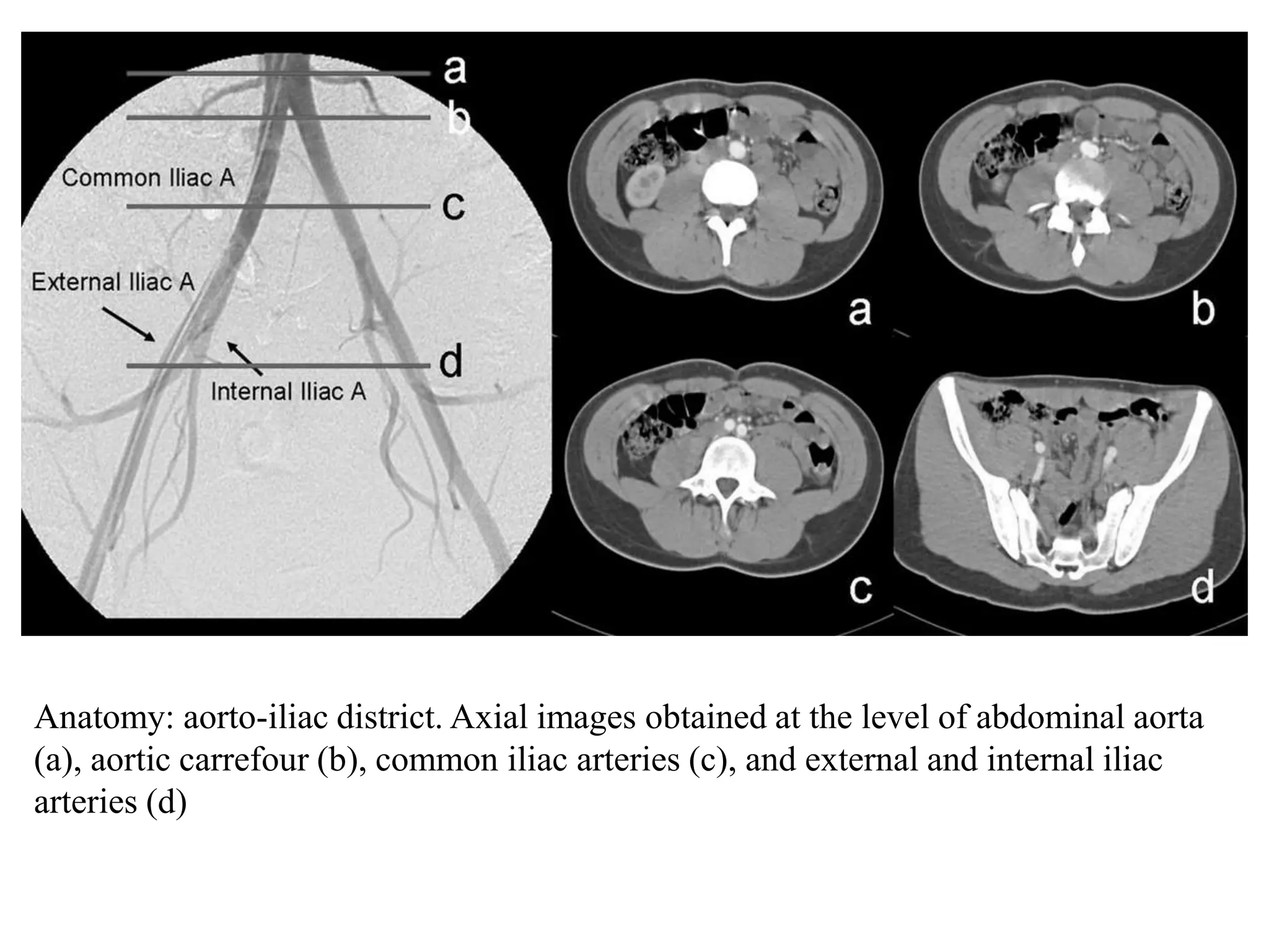
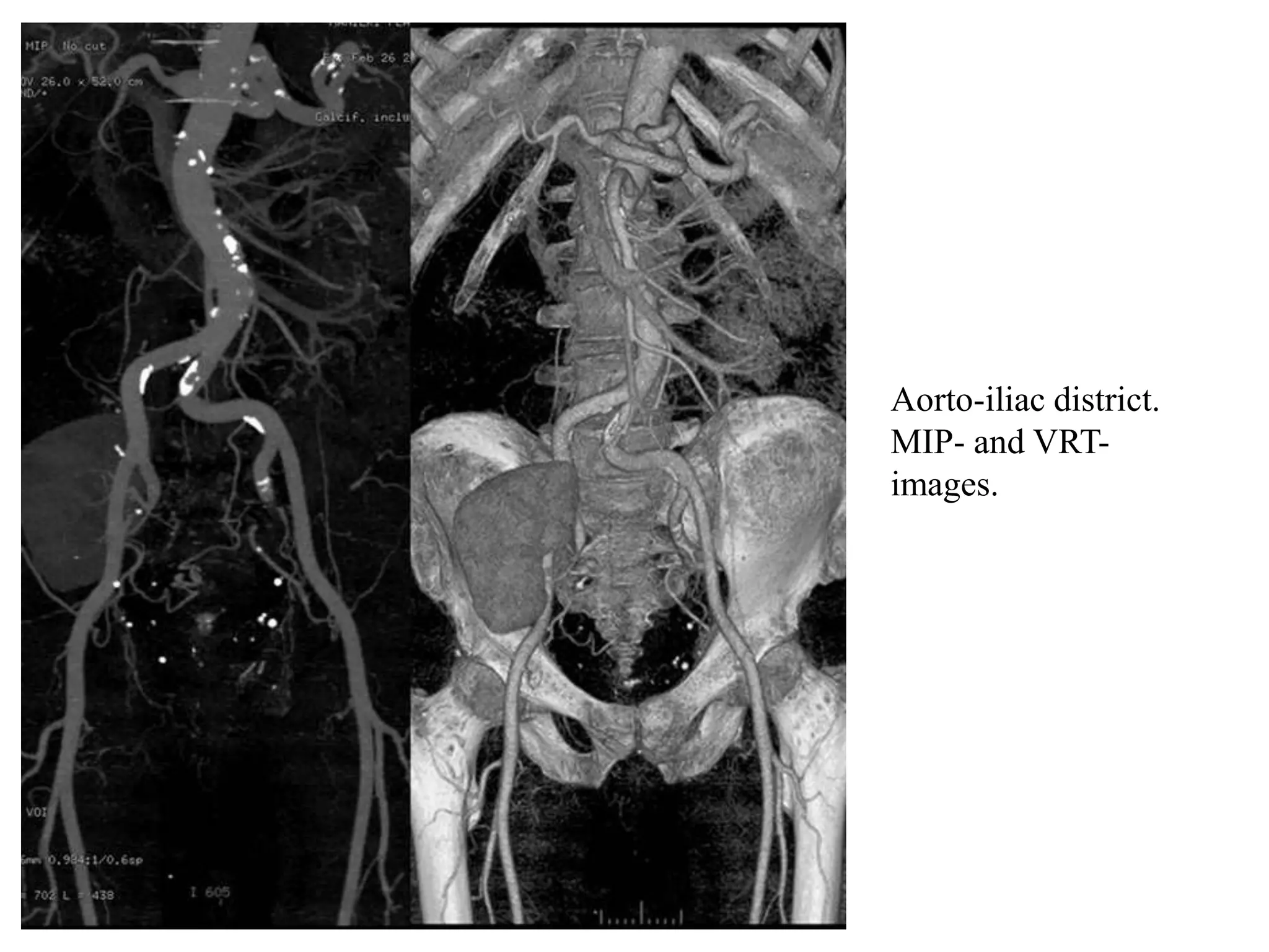
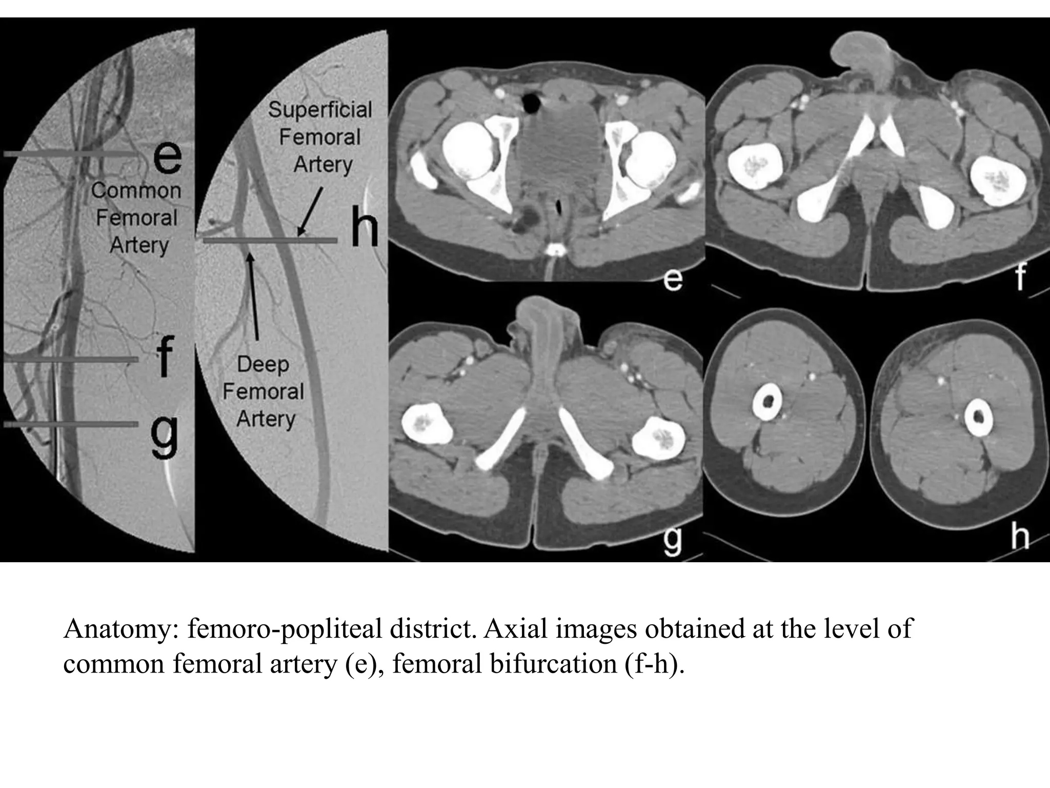
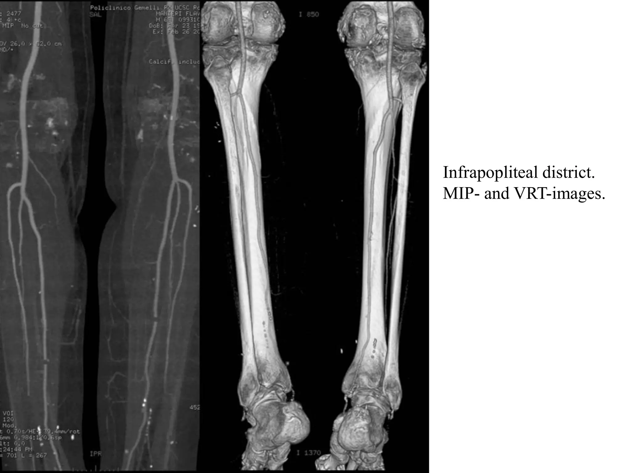
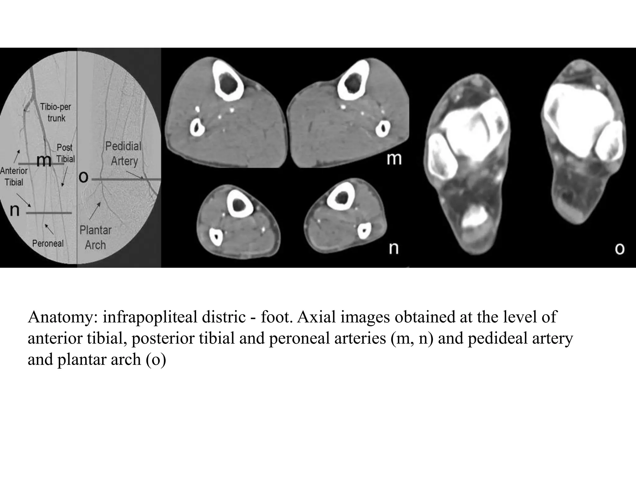
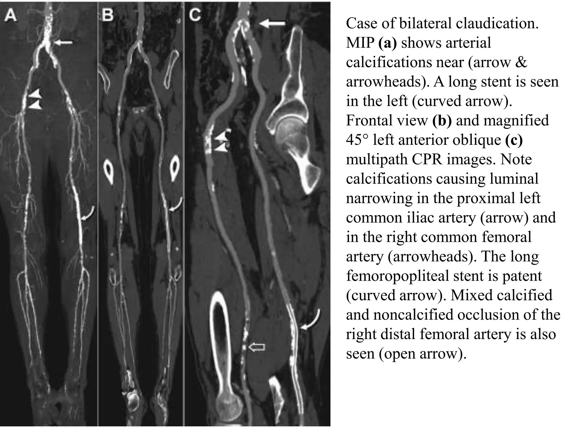
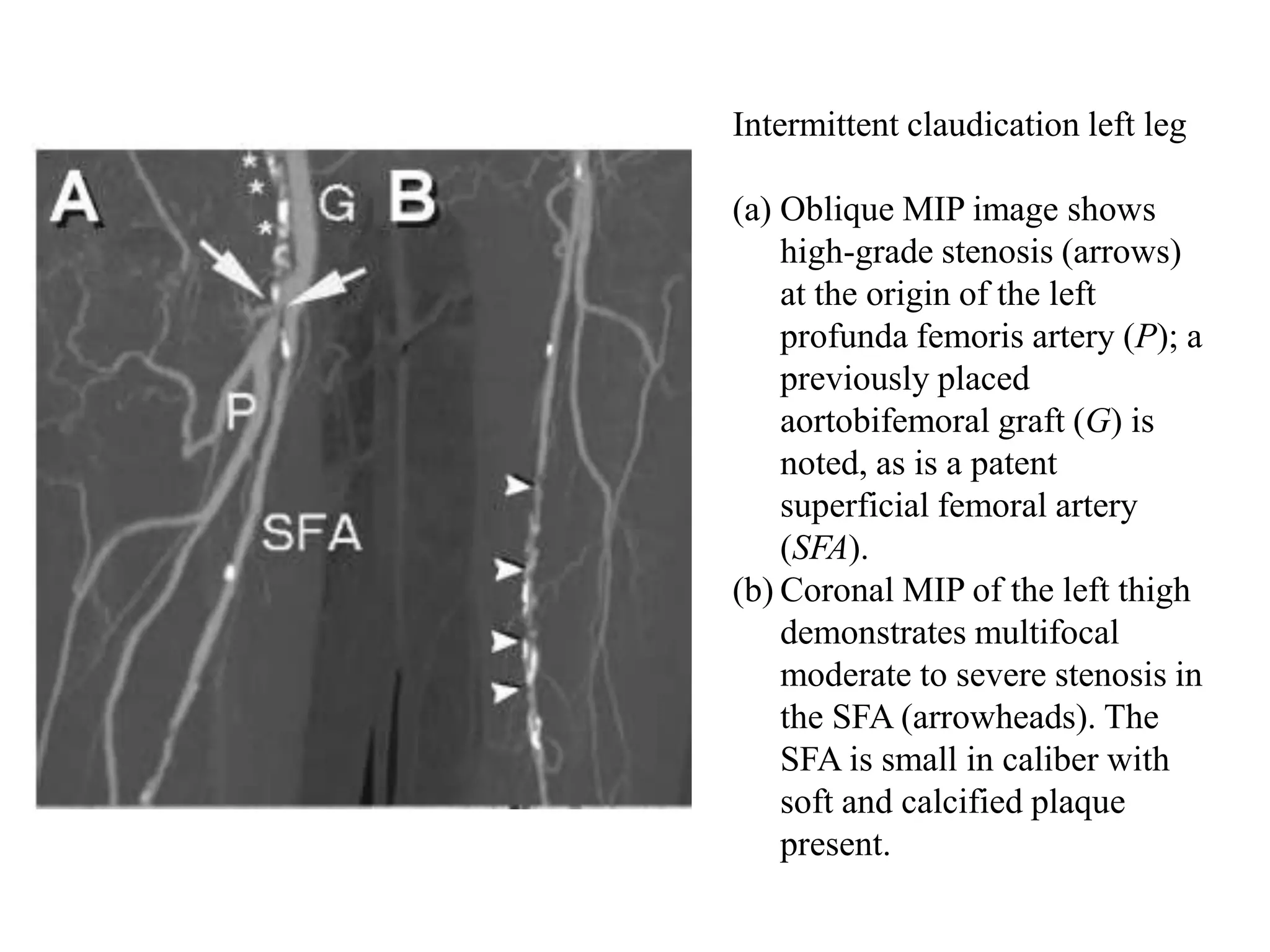
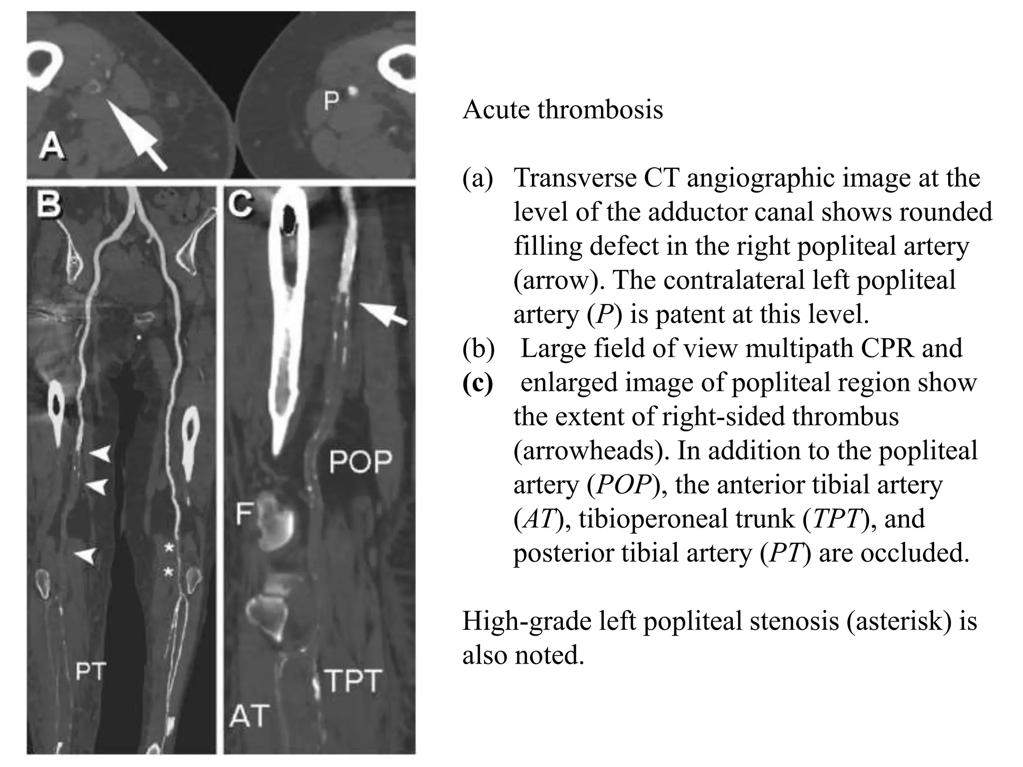
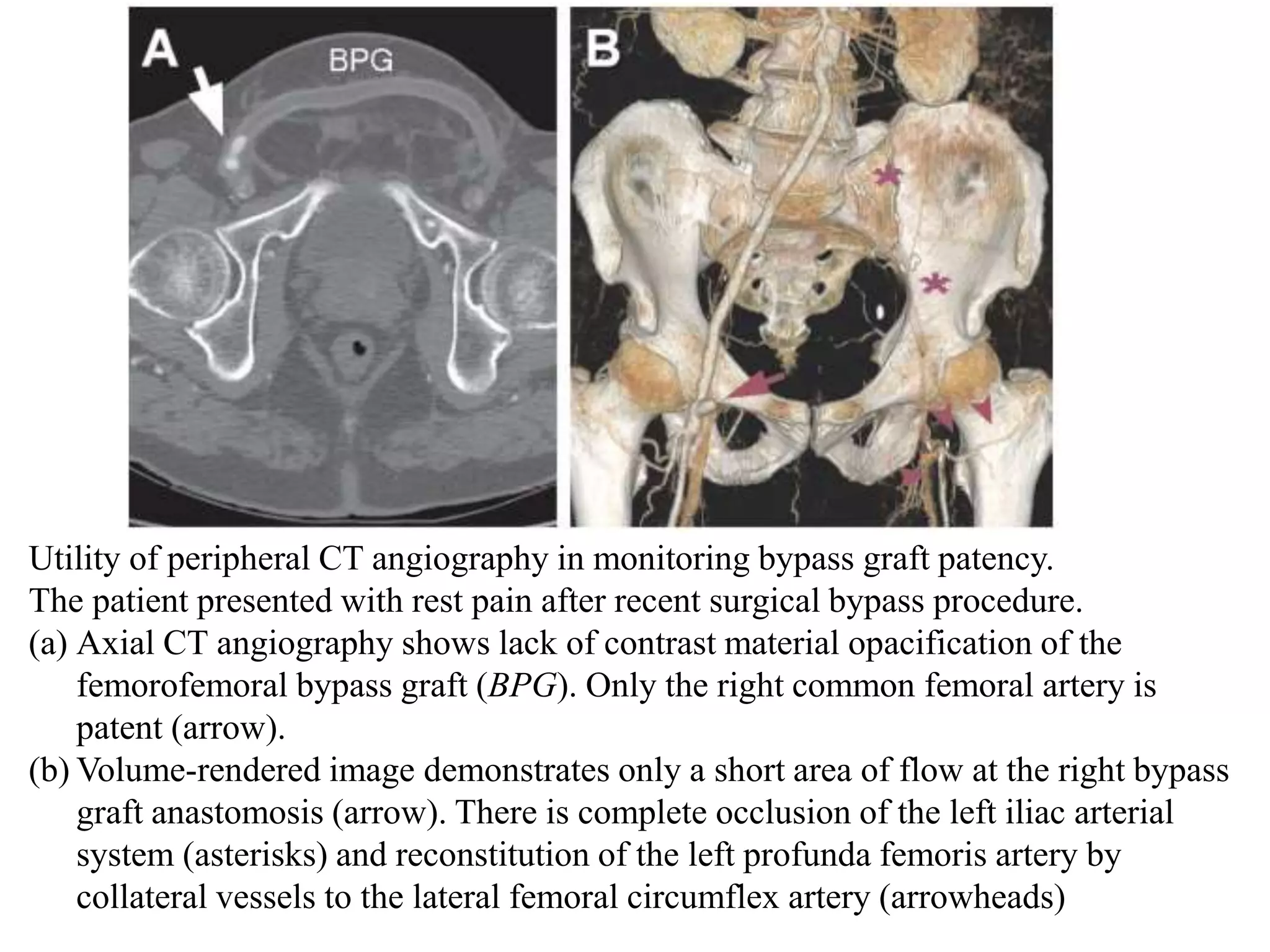
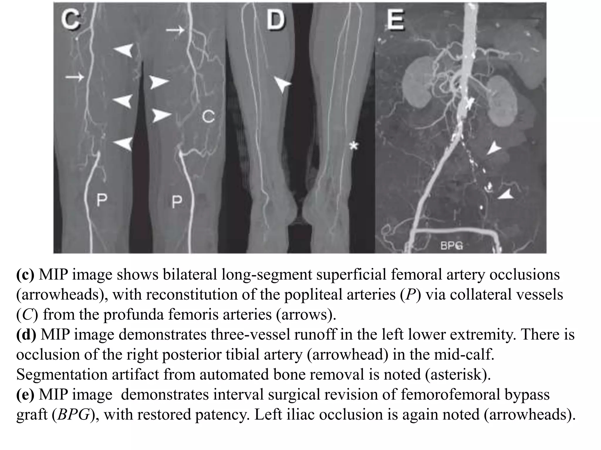
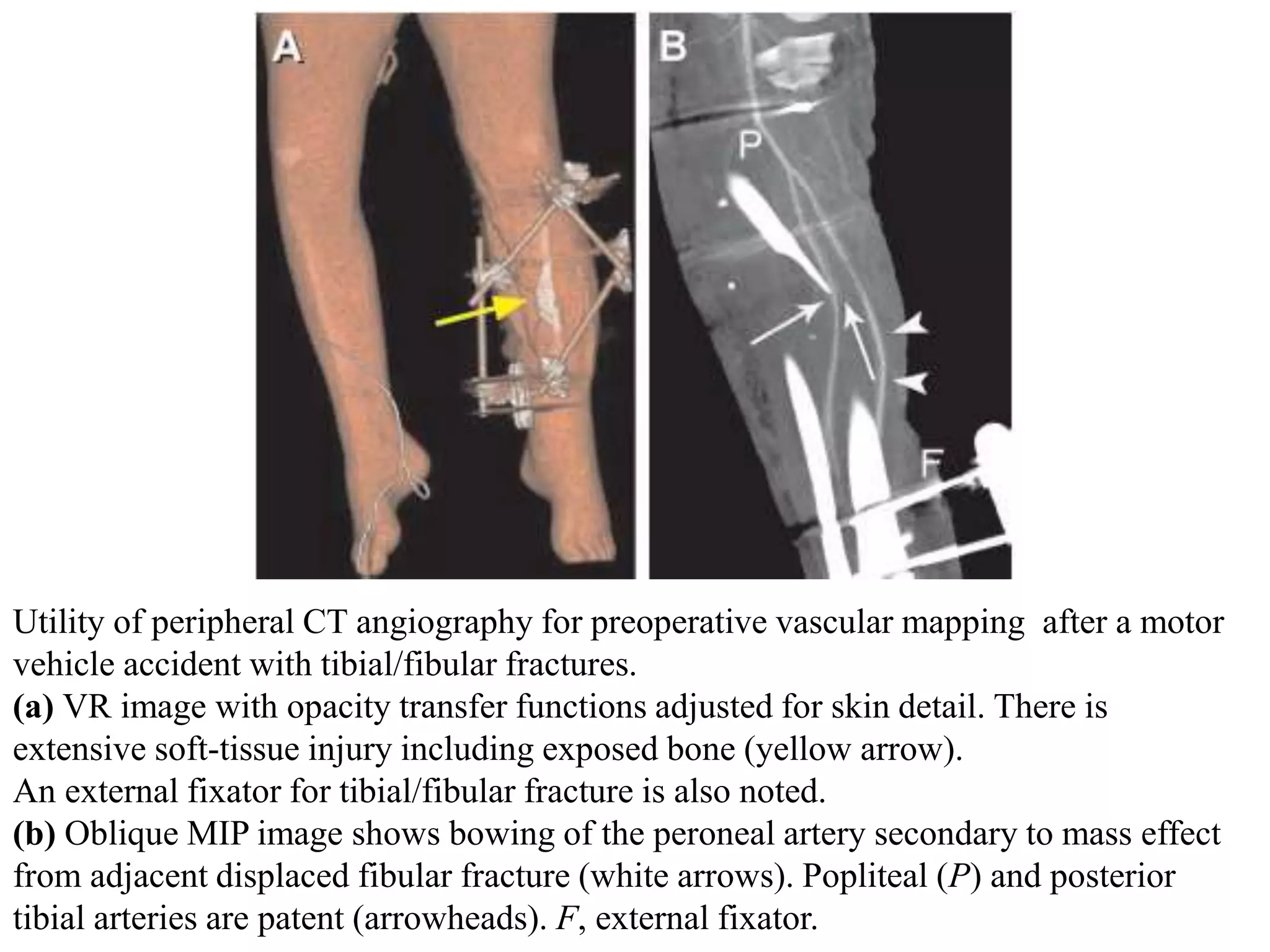
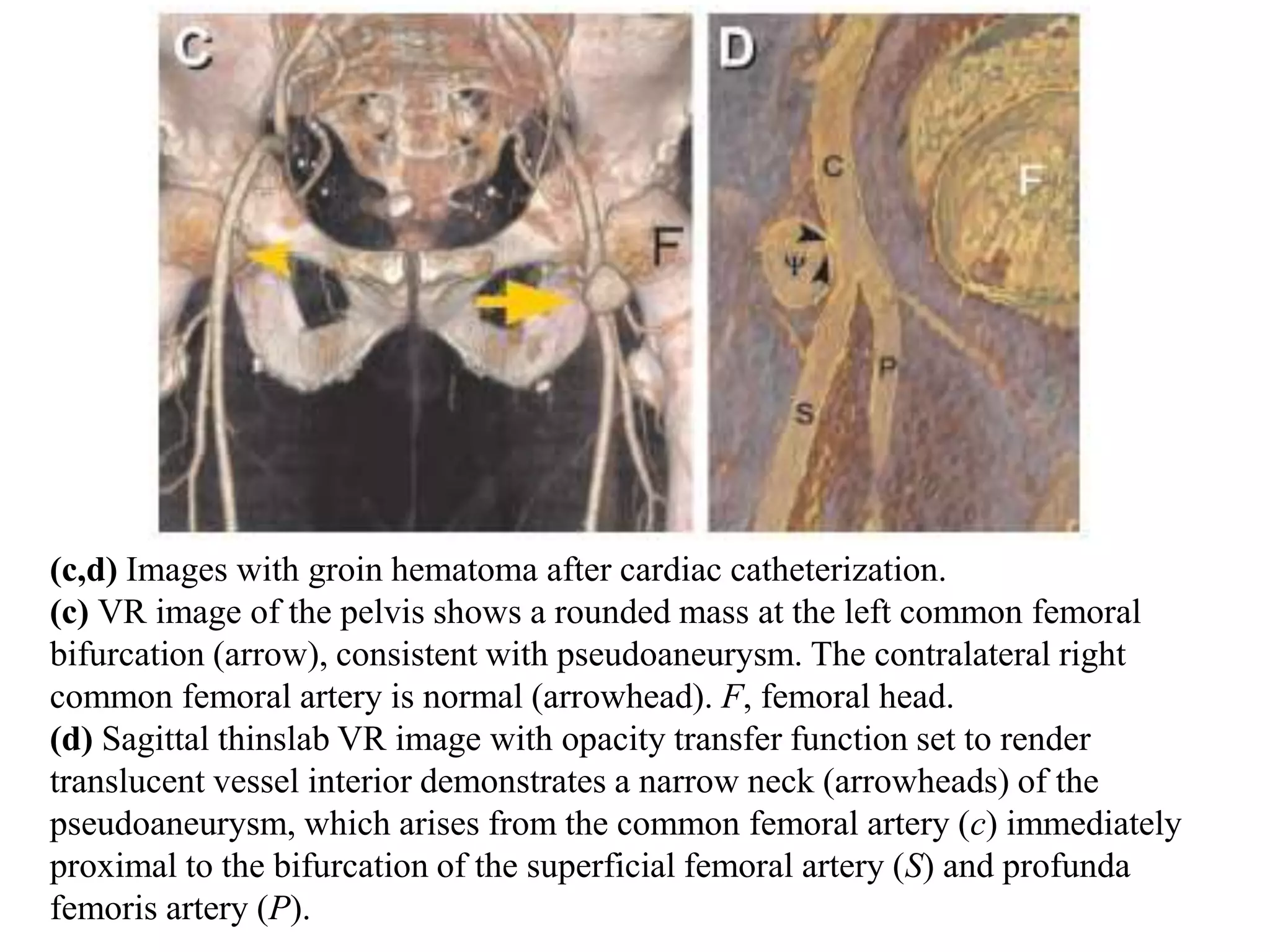
SlideShare a Scribd company logo
Normal CTA Lower Limb
and Applications
Dr. Yash Kumar Achantani
OSR
Introduction
With increasing availability of multiple detector row CT
scanners, peripheral CT angiography has gradually entered
clinical practice , and high resolution imaging of the peripheral
vasculature has become routinely possible.
SCANNING TECHNIQUE
In general, peripheral CT angiography acquisition parameters
follow those of abdominal CT angiography.
A tube voltage of 120 kV and a maximum tube amperage of 300
mA is used for peripheral CT angiography, which results in a
radiation exposure and dose (12.97 mGy, 9.3 mSv).
Breath-holding is required only at the beginning of the CT
acquisition through the abdomen and pelvis.
SCANNING PROTOCOL
A full scanning protocol consists of
(i) The digital radiograph (“scout” image or “topogram”),
(ii) An optional nonenhanced acquisition,
(iii) One series for a test bolus or bolus triggering,
(iv) The actual CT angiography acquisition series, and
(v) A second optional “late phase” CT angiography acquisition
(initiated only on demand) in the event of non opacification of
distal vessels
Digital CT radiograph for prescribing
peripheral CT angiography.
The patient’s legs and feet are aligned
with the long axis of the scanner.
Scanning range (from T12 through the
feet) and reconstruction field of view
(determined by the greater trochanters;
arrows) are indicated by the dotted
line.
A second optional CT angiography
acquisition is prescribed for the
crural/pedal territory (dashed line).
Patient Positioning and Scanning
Range
The patient is placed feet-first and supine on the couch of the
scanner.
To keep the image reconstruction field of view small, and also to
avoid off-center stair-step artefacts , it is important to carefully
align the patient’s legs and feet close to the iso center of the
scanner.
The anatomic coverage extends from the T12 vertebral body level
(to include the renal artery origins) proximally through the
patient’s feet distally.
Image Acquisition and
Reconstruction Parameters
The choice of acquisition parameters (ie, detector configuration
/pitch) and the corresponding reconstruction parameters (ie,
section thickness/reconstruction interval) depends largely on the
type and model of the scanner.
Sixteen-channel CT
When a detector configuration of 16 1.25 mm or 16 1.5 mm is
used, similar high-resolution data sets of the peripheral arterial
tree can be acquired if 1.25–2-mm-thick sections are
reconstructed at 0.8–1-mm intervals.
However, the acquisition speed with these parameter settings is
substantially faster. In fact, it may be too fast for patients with
altered flow dynamics.
Therefore, it is generally not necessary and potentially
detrimental to choose the maximum pitch and/or the fastest
gantry rotation speed with these scanners.
Sixteen-channel CT also allows, for the first time, acquisition of
submillimetre “isotropic” data sets of the entire peripheral
arterial tree with detector configuration settings such as
16 X 0.625 mm or 16 X 0.75 mm.
These isotropic resolution data sets further improve the
visualization of small crural or pedal vessels.
Sixteen-channel CT (16 1.25 mm, 1.25 mm/0.8 mm) peripheral CT angiogram
in a 70-year-old man with right thigh claudication and right iliofemoral artery
occlusion demonstrates exquisite detail of small collateral vessels (a), as well as
femoropopliteal (b)
pedal (c), and crural arteries (d).
Contrast Medium Injection
Technique
Intravenous contrast medium is injected with a power injector
into an antecubital vein with use of a 20 gauge intravenous
cannula.
Peripheral CT angiography is more complex with respect to
synchronizing the enhancement of the entire lower-extremity
arterial tree with the CT data acquisition
speed.
One to 1.5 g of iodine injected per second usually achieves
adequate arterial enhancement for an average (75 kg) person.
With a continuous intravenous injection of contrast medium over
a prolonged period of time (eg, 35 seconds), arterial enhancement
continuously increases over time.
In general, biphasic injections result in more uniform
enhancement over time, notably with long scan and injection
times (25–30 seconds)
Principles of Scan Timing
The time interval between the beginning of an intravenous
contrast material injection and the arrival of the bolus in the aorta,
referred to as the contrast medium transit time, is very variable
among patients with coexisting cardiocirculatory disease, and
may range from 12 to 40 seconds.
A patient’s individual contrast medium transit time can be
reliably determined with a small test bolus injection or estimated
with use of automated bolus triggering techniques.
The scanning delay may then be chosen to equal the contrast
medium transit time (the scan is therefore initiated as soon as
contrast medium arrives in the aorta), or the scanning delay
may be chosen at a predefined interval after the contrast
medium transit time.
For example, the notation “contrast medium transit time + 5
seconds” means that the scan starts 5 seconds after contrast
medium has arrived in the aorta.
The additional challenge in patients with peripheral arterial
occlusive disease is related to the well-known fact that arterial
stenoses, occlusions, or aneurysms anywhere between the
infrarenal abdominal aorta and the pedal arteries may
substantially delay downstream vascular opacification.
The clinical implication for peripheral CT angiography is that
the scanner table may move faster than the intravascular
contrast medium column, and the scanner may therefore
“outrun” the bolus.
Injection Strategies for Slow
Acquisitions
For Detector configuration settings of 4 X 2.5 mm, 8 X 1.25 mm,
and 16 X 0.625 mm
Injection Strategies for Fast
Acquisitions
For Detector configuration settings of 8 X 2.5 mm, 16 X 1.25
mm, or 16 X 1.5 mm.
Visualization and
Image
Interpretation
Transverse Source Image Viewing
Reviewing of transverse CT slices is mandatory for the
assessment of extravascular abdominal or pelvic pathologic
processes.
Axial images also display relevant extravascular anatomy, such as
the course and position of the medial head of the gastrocnemius
muscle in popliteal entrapment syndrome, which may not be
apparent on images such as MIPs.
Source images may also serve as a reference when two-
dimensional or 3D reformatted images suggest artifactual lesions,
for the majority of cases with vascular disease, transverse image
viewing is inefficient and less accurate than viewing reformatted
images
Postprocessing
Techniques
• MIP
• Volume rendering
• Multiplanar reformation
and CPR
Interpretation
and Pitfalls
Probably the most important pitfall related to the interpretation of
peripheral CT angiograms is related to the use of narrow viewing
window settings in the presence of arterial wall calcifications or
stents.
Even at wider than normal CT angiographic window settings
(window level/width, 150/600 HU), high-attenuation objects (eg,
calcified plaque, stents) appear larger than they really are
(“blooming” caused by the point-spread function of the scanner),
which may lead to an overestimation of a vascular stenosis or
suggest a spurious occlusion.
When scrutinizing a calcified lesion or a stent-implanted
segment with use of any of the cross-sectional grayscale images
(eg, transverse source images, MPR, or CPR), a viewing
window width of at least 1,500 HU may be required.
(a) VR image of the left superficial
femoral artery shows excessive vessel
wall calcifications, precluding the
assessment of the flow channel.
Cross-sectional views were required to visualize the vessel lumen.
Axial CT images (b,c) through the mid-superficial femoral artery
(dotted line in a and d) with viewing window settings (level/width) of
200 HU/600 HU (b) does not allow us to distinguish between
opacified vessel lumen and vessel calcification, which can be
distinguished only when an adequately wide window width (300
HU/1,200 HU) is used (c).
Similar wide window settings are
also used for a CPR through the
same vessel (d), displaying several
areas of wall calcification with and
without stenosis.
Other interpretation pitfalls result from misinterpretation of
editing artefacts (e.g., inadvertent vessel removal) in MIP
images and pseudo stenosis and/or occlusions in CPRs
resulting from inaccurate center-line definition.
Normal
Anatomy
Anatomy: aorto-iliac district. Axial images obtained at the level of abdominal aorta
(a), aortic carrefour (b), common iliac arteries (c), and external and internal iliac
arteries (d)
Aorto-iliac district.
MIP- and VRT-
images.
Anatomy: femoro-popliteal district. Axial images obtained at the level of
common femoral artery (e), femoral bifurcation (f-h).
Femoro-
popliteal district.
MIP- and VRT-
images.
Anatomy: popliteal-infrapopliteal district. Axial images obtained at the level of
proximal popliteal artery (i), popliteal artery (j), distal popliteal artery (k), and
anterior tibial artery and tibio-peroneal trunk (l)
Infrapopliteal district.
MIP- and VRT-images.
Anatomy: infrapopliteal distric - foot. Axial images obtained at the level of
anterior tibial, posterior tibial and peroneal arteries (m, n) and pedideal artery
and plantar arch (o)
Foot. VRT-images
CURRENT
CLINICAL
APPLICATIONS
1. Steno-obstructive disease
2. Aneurysmal disease
3. Traumatic lesions
4. Iatrogenic injuries
5. Inflammatory conditions
6. Embolic phenomena
7. Follow-up and surveillance after surgical or percutaneous
revascularization
8. Congenital abnormalities
Case of intermittent claudication
MIP (a) shows long right
femoropopliteal occlusion (curved
arrow) and diffuse disease of the left
superficial femoral artery with a
short distal near-occlusion.
CPR (b) through left iliofemoral
arteries demonstrates multiple mild
stenoses of the external iliac
artery (arrowheads), a diffusely
diseased left superficial femoral
artery, and short (3 cm) distal left
superficial femoral artery occlusion.
Corresponding selective DSA
images of the left external iliac
artery (c) and the distal left
superficial femoral artery (d) were
obtained immediately before
angioplasty/stent implantation.
Case of bilateral claudication.
MIP (a) shows arterial
calcifications near (arrow &
arrowheads). A long stent is seen
in the left (curved arrow).
Frontal view (b) and magnified
45° left anterior oblique (c)
multipath CPR images. Note
calcifications causing luminal
narrowing in the proximal left
common iliac artery (arrow) and
in the right common femoral
artery (arrowheads). The long
femoropopliteal stent is patent
(curved arrow). Mixed calcified
and noncalcified occlusion of the
right distal femoral artery is also
seen (open arrow).
Intermittent claudication left leg
(a) Oblique MIP image shows
high-grade stenosis (arrows)
at the origin of the left
profunda femoris artery (P); a
previously placed
aortobifemoral graft (G) is
noted, as is a patent
superficial femoral artery
(SFA).
(b) Coronal MIP of the left thigh
demonstrates multifocal
moderate to severe stenosis in
the SFA (arrowheads). The
SFA is small in caliber with
soft and calcified plaque
present.
(c) Coronal MIP of the calf
shows a one-vessel runoff
(peroneal; PER) to the left foot.
Mild venous contamination (V)
is present.
(d) Sagittal MIP image of the
left foot shows collateral vessel
reconstitution (arrowheads) of
the dorsalis pedis (DP) above
the ankle from the peroneal
artery
Perianastomotic pseudoaneurysms with history of aortobifemoral bypass grafting.
(a) VR image demonstrates bilateral perianastomotic pseudoaneurysms at the distal
attachment sites of the aortobifemoral graft and common femoral arteries (arrows).
There is a long-segment superficial femoral artery occlusion on the left
(arrowheads) with collateral vessels from the profunda femoris artery (c).
(b) VR image shows the profile of the pseudoaneurysm (arrow), as well as the adjacent
native external iliac artery (arrowheads).
(c) VR image of the left thigh demonstrates abundant profunda collateral supply (c).
The length of the occluded segment was approximately 11 cm (arrowheads)
Acute thrombosis
(a) Transverse CT angiographic image at the
level of the adductor canal shows rounded
filling defect in the right popliteal artery
(arrow). The contralateral left popliteal
artery (P) is patent at this level.
(b) Large field of view multipath CPR and
(c) enlarged image of popliteal region show
the extent of right-sided thrombus
(arrowheads). In addition to the popliteal
artery (POP), the anterior tibial artery
(AT), tibioperoneal trunk (TPT), and
posterior tibial artery (PT) are occluded.
High-grade left popliteal stenosis (asterisk) is
also noted.
Utility of peripheral CT angiography in monitoring bypass graft patency.
The patient presented with rest pain after recent surgical bypass procedure.
(a) Axial CT angiography shows lack of contrast material opacification of the
femorofemoral bypass graft (BPG). Only the right common femoral artery is
patent (arrow).
(b) Volume-rendered image demonstrates only a short area of flow at the right bypass
graft anastomosis (arrow). There is complete occlusion of the left iliac arterial
system (asterisks) and reconstitution of the left profunda femoris artery by
collateral vessels to the lateral femoral circumflex artery (arrowheads)
(c) MIP image shows bilateral long-segment superficial femoral artery occlusions
(arrowheads), with reconstitution of the popliteal arteries (P) via collateral vessels
(C) from the profunda femoris arteries (arrows).
(d) MIP image demonstrates three-vessel runoff in the left lower extremity. There is
occlusion of the right posterior tibial artery (arrowhead) in the mid-calf.
Segmentation artifact from automated bone removal is noted (asterisk).
(e) MIP image demonstrates interval surgical revision of femorofemoral bypass
graft (BPG), with restored patency. Left iliac occlusion is again noted (arrowheads).
Utility of peripheral CT angiography for preoperative vascular mapping after a motor
vehicle accident with tibial/fibular fractures.
(a) VR image with opacity transfer functions adjusted for skin detail. There is
extensive soft-tissue injury including exposed bone (yellow arrow).
An external fixator for tibial/fibular fracture is also noted.
(b) Oblique MIP image shows bowing of the peroneal artery secondary to mass effect
from adjacent displaced fibular fracture (white arrows). Popliteal (P) and posterior
tibial arteries are patent (arrowheads). F, external fixator.
Images of adventitial cystic
disease.
(a) Axial source image from
peripheral CT angiography
shows marked compression of
the popliteal artery (P) by an
ovoid fluid-density lesion
(arrowheads). Note the
predominant transverse
compression of the flow lumen.
F, fabella.
(b) Corresponding sagittal thin-
slab MIP image shows
craniocaudal extent of fluid-
density lesion in the popliteal
arterial wall (arrowheads).
(c) VR image viewed obliquely
from the posterior direction
demonstrates severe narrowing
of the right popliteal artery
(arrows).
(a,b) Peripheral CT angiography of penetrating trauma with a gunshot wound to the
left leg.
(a) Posterior VR image and (b) oblique thin-slab MIP image of the left calf show a
lobulated pseudoaneurysm arising from the peroneal artery (arrow). The immediate
distal peroneal artery shows luminal narrowing, most likely spasm (arrowhead).
(c,d) Images with groin hematoma after cardiac catheterization.
(c) VR image of the pelvis shows a rounded mass at the left common femoral
bifurcation (arrow), consistent with pseudoaneurysm. The contralateral right
common femoral artery is normal (arrowhead). F, femoral head.
(d) Sagittal thinslab VR image with opacity transfer function set to render
translucent vessel interior demonstrates a narrow neck (arrowheads) of the
pseudoaneurysm, which arises from the common femoral artery (c) immediately
proximal to the bifurcation of the superficial femoral artery (S) and profunda
femoris artery (P).
MIP- and VRT-images:
popliteal aneurysm
Buerger’s Disease:- Occluded right anterior tibial and peroneal arteries at their
origin, patent proximal half of the posterior tibial artery with occluded its distal
half.
Occlusion of the left anterior and posterior tibial arteries following patent short
proximal segments. Patent peroneal artery.
Multiple dilated corkscrew collaterals are noted bilaterally.
Trans-Atlantic Inter-Society
Consensus Document
classification of femoral
popliteal lesions
Thank You

More Related Content

What's hot

Radiology Spotters
Radiology Spotters Radiology Spotters
Radiology Spotters
Anish Choudhary
 
magnetic resonance angiography
magnetic resonance angiographymagnetic resonance angiography
magnetic resonance angiography
qavi786
 
MRI artifacts
MRI artifactsMRI artifacts
MRI artifacts
Sudil Paudyal
 
Radiology Spots PPT- 2 by Dr Chandni Wadhwani
Radiology Spots PPT- 2 by Dr Chandni WadhwaniRadiology Spots PPT- 2 by Dr Chandni Wadhwani
Radiology Spots PPT- 2 by Dr Chandni Wadhwani
Chandni Wadhwani
 
Radiological imaging of mediastinal masses
Radiological imaging of mediastinal massesRadiological imaging of mediastinal masses
Radiological imaging of mediastinal masses
Pankaj Kaira
 
Diffusion Weighted Imaging- Avinesh Shrestha
Diffusion Weighted Imaging- Avinesh ShresthaDiffusion Weighted Imaging- Avinesh Shrestha
Diffusion Weighted Imaging- Avinesh Shrestha
Avinesh Shrestha
 
MRI KNEE JOINT ANATOMY
MRI KNEE JOINT ANATOMYMRI KNEE JOINT ANATOMY
MRI KNEE JOINT ANATOMY
Nikhil Bansal
 
Triple phase ct PowerPoint slide PPT pk
Triple phase ct PowerPoint slide PPT pkTriple phase ct PowerPoint slide PPT pk
Triple phase ct PowerPoint slide PPT pk
Dr pradeep Kumar
 
lower limb doppler examination -The essentials
lower limb doppler examination -The essentialslower limb doppler examination -The essentials
lower limb doppler examination -The essentials
Ahmed Bahnassy
 
Ct mri urography
Ct mri urographyCt mri urography
Ct mri urography
Dev Lakhera
 
Presentation1, radiological imaging of barium studies.
Presentation1, radiological imaging of barium studies.Presentation1, radiological imaging of barium studies.
Presentation1, radiological imaging of barium studies.
Abdellah Nazeer
 
Dose reduction technique in ct scan
Dose reduction technique in ct scanDose reduction technique in ct scan
Dose reduction technique in ct scan
Mohd Aiman Azmardi
 
PTBD (Percutaneus trans-hepatic biliary drainage) PPT,PDF PK
PTBD (Percutaneus trans-hepatic biliary drainage) PPT,PDF PKPTBD (Percutaneus trans-hepatic biliary drainage) PPT,PDF PK
PTBD (Percutaneus trans-hepatic biliary drainage) PPT,PDF PK
Dr pradeep Kumar
 
Computed Tomography of Liver and Pancreas- Avinesh Shrestha
Computed Tomography of Liver and Pancreas- Avinesh ShresthaComputed Tomography of Liver and Pancreas- Avinesh Shrestha
Computed Tomography of Liver and Pancreas- Avinesh Shrestha
Avinesh Shrestha
 
Mr imaging of spine
Mr imaging of spineMr imaging of spine
Mr imaging of spine
Dr. Muhammad Bin Zulfiqar
 
Doppler ultrasound of carotid arteries
Doppler ultrasound of carotid arteriesDoppler ultrasound of carotid arteries
Doppler ultrasound of carotid arteriesSamir Haffar
 
CT Cervical Spine
CT Cervical SpineCT Cervical Spine
CT Cervical Spine
Dr. Yash Kumar Achantani
 
Larynx anatomy CT and MRI
Larynx anatomy CT and MRILarynx anatomy CT and MRI
Larynx anatomy CT and MRI
Dr. Mohit Goel
 
Imaging of the Pancreas
Imaging of the PancreasImaging of the Pancreas
Imaging of the PancreasAtit Ghoda
 
Imaging in Skull base
Imaging in Skull baseImaging in Skull base
Imaging in Skull base
Rakesh Ca
 

What's hot (20)

Radiology Spotters
Radiology Spotters Radiology Spotters
Radiology Spotters
 
magnetic resonance angiography
magnetic resonance angiographymagnetic resonance angiography
magnetic resonance angiography
 
MRI artifacts
MRI artifactsMRI artifacts
MRI artifacts
 
Radiology Spots PPT- 2 by Dr Chandni Wadhwani
Radiology Spots PPT- 2 by Dr Chandni WadhwaniRadiology Spots PPT- 2 by Dr Chandni Wadhwani
Radiology Spots PPT- 2 by Dr Chandni Wadhwani
 
Radiological imaging of mediastinal masses
Radiological imaging of mediastinal massesRadiological imaging of mediastinal masses
Radiological imaging of mediastinal masses
 
Diffusion Weighted Imaging- Avinesh Shrestha
Diffusion Weighted Imaging- Avinesh ShresthaDiffusion Weighted Imaging- Avinesh Shrestha
Diffusion Weighted Imaging- Avinesh Shrestha
 
MRI KNEE JOINT ANATOMY
MRI KNEE JOINT ANATOMYMRI KNEE JOINT ANATOMY
MRI KNEE JOINT ANATOMY
 
Triple phase ct PowerPoint slide PPT pk
Triple phase ct PowerPoint slide PPT pkTriple phase ct PowerPoint slide PPT pk
Triple phase ct PowerPoint slide PPT pk
 
lower limb doppler examination -The essentials
lower limb doppler examination -The essentialslower limb doppler examination -The essentials
lower limb doppler examination -The essentials
 
Ct mri urography
Ct mri urographyCt mri urography
Ct mri urography
 
Presentation1, radiological imaging of barium studies.
Presentation1, radiological imaging of barium studies.Presentation1, radiological imaging of barium studies.
Presentation1, radiological imaging of barium studies.
 
Dose reduction technique in ct scan
Dose reduction technique in ct scanDose reduction technique in ct scan
Dose reduction technique in ct scan
 
PTBD (Percutaneus trans-hepatic biliary drainage) PPT,PDF PK
PTBD (Percutaneus trans-hepatic biliary drainage) PPT,PDF PKPTBD (Percutaneus trans-hepatic biliary drainage) PPT,PDF PK
PTBD (Percutaneus trans-hepatic biliary drainage) PPT,PDF PK
 
Computed Tomography of Liver and Pancreas- Avinesh Shrestha
Computed Tomography of Liver and Pancreas- Avinesh ShresthaComputed Tomography of Liver and Pancreas- Avinesh Shrestha
Computed Tomography of Liver and Pancreas- Avinesh Shrestha
 
Mr imaging of spine
Mr imaging of spineMr imaging of spine
Mr imaging of spine
 
Doppler ultrasound of carotid arteries
Doppler ultrasound of carotid arteriesDoppler ultrasound of carotid arteries
Doppler ultrasound of carotid arteries
 
CT Cervical Spine
CT Cervical SpineCT Cervical Spine
CT Cervical Spine
 
Larynx anatomy CT and MRI
Larynx anatomy CT and MRILarynx anatomy CT and MRI
Larynx anatomy CT and MRI
 
Imaging of the Pancreas
Imaging of the PancreasImaging of the Pancreas
Imaging of the Pancreas
 
Imaging in Skull base
Imaging in Skull baseImaging in Skull base
Imaging in Skull base
 

Similar to CT Angiography Lower Limb

Hofer ct teaching manual - a systematic approach to ct reading, 2nd ed.
Hofer   ct teaching manual - a systematic approach to ct reading,  2nd ed.Hofer   ct teaching manual - a systematic approach to ct reading,  2nd ed.
Hofer ct teaching manual - a systematic approach to ct reading, 2nd ed.
Michel Phuong
 
Ct angio ppt
Ct angio pptCt angio ppt
Ct angio ppt
drksp
 
cardiovascular ct ppt
cardiovascular ct pptcardiovascular ct ppt
cardiovascular ct ppt
drksp
 
Ct angio in cardiology
Ct angio in cardiologyCt angio in cardiology
Ct angio in cardiology
Amit Verma
 
Thoracic aorta mri nice
Thoracic aorta mri niceThoracic aorta mri nice
Thoracic aorta mri nice
Praveen Kumar
 
Intracoronaryopticalcoherencetomography 130909083234-
Intracoronaryopticalcoherencetomography 130909083234-Intracoronaryopticalcoherencetomography 130909083234-
Intracoronaryopticalcoherencetomography 130909083234-
Mashiul Alam
 
Chronic total occlusion
Chronic total occlusionChronic total occlusion
Chronic total occlusion
Dr Virbhan Balai
 
Ct scan
Ct scanCt scan
Ann Vasc Surg 2012 Funnel Technique
Ann Vasc Surg 2012 Funnel TechniqueAnn Vasc Surg 2012 Funnel Technique
Ann Vasc Surg 2012 Funnel Technique
Salvatore Ronsivalle
 
CT perfusion
CT perfusionCT perfusion
CT perfusion
Pooja Saji
 
Youssef Abdelwahed: Preprocedural CT – which patient needs it
Youssef Abdelwahed: Preprocedural CT – which patient needs itYoussef Abdelwahed: Preprocedural CT – which patient needs it
Youssef Abdelwahed: Preprocedural CT – which patient needs it
Euro CTO Club
 
coronary imaging
coronary imagingcoronary imaging
2018 behrens-patient-spezcific
2018 behrens-patient-spezcific2018 behrens-patient-spezcific
2018 behrens-patient-spezcific
Klinikum Lippe GmbH
 
CT, MRI in vascular surgery
CT, MRI in vascular surgery CT, MRI in vascular surgery
CT, MRI in vascular surgery
Tapish Sahu
 
First Clinical Results of Coronary CT Subtraction
First Clinical Results of Coronary CT SubtractionFirst Clinical Results of Coronary CT Subtraction
First Clinical Results of Coronary CT Subtraction
Canon Medical Systems Europe
 
CT and MRI of Aortic Valve Disease: Clinical Update
CT and MRI of Aortic Valve Disease: Clinical Update CT and MRI of Aortic Valve Disease: Clinical Update
CT and MRI of Aortic Valve Disease: Clinical Update
Sam Watermeier
 
7200 35328
7200 353287200 35328
Usefulness of Non-Enhanced 3-Dementional CT with Partial Maximum Intensity Pr...
Usefulness of Non-Enhanced 3-Dementional CT with Partial Maximum Intensity Pr...Usefulness of Non-Enhanced 3-Dementional CT with Partial Maximum Intensity Pr...
Usefulness of Non-Enhanced 3-Dementional CT with Partial Maximum Intensity Pr...
science journals
 
Atlas of advanced endoaortic surgery
Atlas of advanced endoaortic surgeryAtlas of advanced endoaortic surgery
Atlas of advanced endoaortic surgerySpringer
 
Atlas of advanced endoaortic surgery
Atlas of advanced endoaortic surgeryAtlas of advanced endoaortic surgery
Atlas of advanced endoaortic surgerySpringer
 

Similar to CT Angiography Lower Limb (20)

Hofer ct teaching manual - a systematic approach to ct reading, 2nd ed.
Hofer   ct teaching manual - a systematic approach to ct reading,  2nd ed.Hofer   ct teaching manual - a systematic approach to ct reading,  2nd ed.
Hofer ct teaching manual - a systematic approach to ct reading, 2nd ed.
 
Ct angio ppt
Ct angio pptCt angio ppt
Ct angio ppt
 
cardiovascular ct ppt
cardiovascular ct pptcardiovascular ct ppt
cardiovascular ct ppt
 
Ct angio in cardiology
Ct angio in cardiologyCt angio in cardiology
Ct angio in cardiology
 
Thoracic aorta mri nice
Thoracic aorta mri niceThoracic aorta mri nice
Thoracic aorta mri nice
 
Intracoronaryopticalcoherencetomography 130909083234-
Intracoronaryopticalcoherencetomography 130909083234-Intracoronaryopticalcoherencetomography 130909083234-
Intracoronaryopticalcoherencetomography 130909083234-
 
Chronic total occlusion
Chronic total occlusionChronic total occlusion
Chronic total occlusion
 
Ct scan
Ct scanCt scan
Ct scan
 
Ann Vasc Surg 2012 Funnel Technique
Ann Vasc Surg 2012 Funnel TechniqueAnn Vasc Surg 2012 Funnel Technique
Ann Vasc Surg 2012 Funnel Technique
 
CT perfusion
CT perfusionCT perfusion
CT perfusion
 
Youssef Abdelwahed: Preprocedural CT – which patient needs it
Youssef Abdelwahed: Preprocedural CT – which patient needs itYoussef Abdelwahed: Preprocedural CT – which patient needs it
Youssef Abdelwahed: Preprocedural CT – which patient needs it
 
coronary imaging
coronary imagingcoronary imaging
coronary imaging
 
2018 behrens-patient-spezcific
2018 behrens-patient-spezcific2018 behrens-patient-spezcific
2018 behrens-patient-spezcific
 
CT, MRI in vascular surgery
CT, MRI in vascular surgery CT, MRI in vascular surgery
CT, MRI in vascular surgery
 
First Clinical Results of Coronary CT Subtraction
First Clinical Results of Coronary CT SubtractionFirst Clinical Results of Coronary CT Subtraction
First Clinical Results of Coronary CT Subtraction
 
CT and MRI of Aortic Valve Disease: Clinical Update
CT and MRI of Aortic Valve Disease: Clinical Update CT and MRI of Aortic Valve Disease: Clinical Update
CT and MRI of Aortic Valve Disease: Clinical Update
 
7200 35328
7200 353287200 35328
7200 35328
 
Usefulness of Non-Enhanced 3-Dementional CT with Partial Maximum Intensity Pr...
Usefulness of Non-Enhanced 3-Dementional CT with Partial Maximum Intensity Pr...Usefulness of Non-Enhanced 3-Dementional CT with Partial Maximum Intensity Pr...
Usefulness of Non-Enhanced 3-Dementional CT with Partial Maximum Intensity Pr...
 
Atlas of advanced endoaortic surgery
Atlas of advanced endoaortic surgeryAtlas of advanced endoaortic surgery
Atlas of advanced endoaortic surgery
 
Atlas of advanced endoaortic surgery
Atlas of advanced endoaortic surgeryAtlas of advanced endoaortic surgery
Atlas of advanced endoaortic surgery
 

More from Dr. Yash Kumar Achantani

USG of Aorta and Coeliac axis
USG of Aorta and Coeliac axisUSG of Aorta and Coeliac axis
USG of Aorta and Coeliac axis
Dr. Yash Kumar Achantani
 
TACE- Transarterial Chemoembolisation
TACE- Transarterial Chemoembolisation TACE- Transarterial Chemoembolisation
TACE- Transarterial Chemoembolisation
Dr. Yash Kumar Achantani
 
Retrograde Pyelography
Retrograde PyelographyRetrograde Pyelography
Retrograde Pyelography
Dr. Yash Kumar Achantani
 
Imaging of Renal Tumors
Imaging of Renal TumorsImaging of Renal Tumors
Imaging of Renal Tumors
Dr. Yash Kumar Achantani
 
Renal isotope scan
Renal isotope scanRenal isotope scan
Renal isotope scan
Dr. Yash Kumar Achantani
 
Post Processing of CT Thorax
Post Processing of CT ThoraxPost Processing of CT Thorax
Post Processing of CT Thorax
Dr. Yash Kumar Achantani
 
Imaging of Obstructive jaundice
Imaging of Obstructive jaundiceImaging of Obstructive jaundice
Imaging of Obstructive jaundice
Dr. Yash Kumar Achantani
 
HIDA Scan
HIDA ScanHIDA Scan
MRI in CVA
MRI in CVAMRI in CVA
CT Urography
CT UrographyCT Urography
CT Imaging of CA Esophagus
CT Imaging of CA EsophagusCT Imaging of CA Esophagus
CT Imaging of CA Esophagus
Dr. Yash Kumar Achantani
 
CT - Lung Carcinoma
CT - Lung CarcinomaCT - Lung Carcinoma
CT - Lung Carcinoma
Dr. Yash Kumar Achantani
 
Biliary drainage
Biliary drainageBiliary drainage
Biliary drainage
Dr. Yash Kumar Achantani
 
Liver cirrhosis USG
Liver cirrhosis USGLiver cirrhosis USG
Liver cirrhosis USG
Dr. Yash Kumar Achantani
 
MRI in Tibial Fractures
MRI in Tibial FracturesMRI in Tibial Fractures
MRI in Tibial Fractures
Dr. Yash Kumar Achantani
 
Basics of Renal Doppler
Basics of Renal DopplerBasics of Renal Doppler
Basics of Renal Doppler
Dr. Yash Kumar Achantani
 
Renal Angiography
Renal AngiographyRenal Angiography
Renal Angiography
Dr. Yash Kumar Achantani
 
Imaging of Large Bowel Polyp
Imaging of Large Bowel PolypImaging of Large Bowel Polyp
Imaging of Large Bowel Polyp
Dr. Yash Kumar Achantani
 
Esophageal stent
Esophageal stentEsophageal stent
Esophageal stent
Dr. Yash Kumar Achantani
 
CTV and MRV
CTV and MRVCTV and MRV

More from Dr. Yash Kumar Achantani (20)

USG of Aorta and Coeliac axis
USG of Aorta and Coeliac axisUSG of Aorta and Coeliac axis
USG of Aorta and Coeliac axis
 
TACE- Transarterial Chemoembolisation
TACE- Transarterial Chemoembolisation TACE- Transarterial Chemoembolisation
TACE- Transarterial Chemoembolisation
 
Retrograde Pyelography
Retrograde PyelographyRetrograde Pyelography
Retrograde Pyelography
 
Imaging of Renal Tumors
Imaging of Renal TumorsImaging of Renal Tumors
Imaging of Renal Tumors
 
Renal isotope scan
Renal isotope scanRenal isotope scan
Renal isotope scan
 
Post Processing of CT Thorax
Post Processing of CT ThoraxPost Processing of CT Thorax
Post Processing of CT Thorax
 
Imaging of Obstructive jaundice
Imaging of Obstructive jaundiceImaging of Obstructive jaundice
Imaging of Obstructive jaundice
 
HIDA Scan
HIDA ScanHIDA Scan
HIDA Scan
 
MRI in CVA
MRI in CVAMRI in CVA
MRI in CVA
 
CT Urography
CT UrographyCT Urography
CT Urography
 
CT Imaging of CA Esophagus
CT Imaging of CA EsophagusCT Imaging of CA Esophagus
CT Imaging of CA Esophagus
 
CT - Lung Carcinoma
CT - Lung CarcinomaCT - Lung Carcinoma
CT - Lung Carcinoma
 
Biliary drainage
Biliary drainageBiliary drainage
Biliary drainage
 
Liver cirrhosis USG
Liver cirrhosis USGLiver cirrhosis USG
Liver cirrhosis USG
 
MRI in Tibial Fractures
MRI in Tibial FracturesMRI in Tibial Fractures
MRI in Tibial Fractures
 
Basics of Renal Doppler
Basics of Renal DopplerBasics of Renal Doppler
Basics of Renal Doppler
 
Renal Angiography
Renal AngiographyRenal Angiography
Renal Angiography
 
Imaging of Large Bowel Polyp
Imaging of Large Bowel PolypImaging of Large Bowel Polyp
Imaging of Large Bowel Polyp
 
Esophageal stent
Esophageal stentEsophageal stent
Esophageal stent
 
CTV and MRV
CTV and MRVCTV and MRV
CTV and MRV
 

Recently uploaded

The Challenger.pdf DNHS Official Publication
The Challenger.pdf DNHS Official PublicationThe Challenger.pdf DNHS Official Publication
The Challenger.pdf DNHS Official Publication
Delapenabediema
 
The basics of sentences session 5pptx.pptx
The basics of sentences session 5pptx.pptxThe basics of sentences session 5pptx.pptx
The basics of sentences session 5pptx.pptx
heathfieldcps1
 
Chapter 3 - Islamic Banking Products and Services.pptx
Chapter 3 - Islamic Banking Products and Services.pptxChapter 3 - Islamic Banking Products and Services.pptx
Chapter 3 - Islamic Banking Products and Services.pptx
Mohd Adib Abd Muin, Senior Lecturer at Universiti Utara Malaysia
 
Honest Reviews of Tim Han LMA Course Program.pptx
Honest Reviews of Tim Han LMA Course Program.pptxHonest Reviews of Tim Han LMA Course Program.pptx
Honest Reviews of Tim Han LMA Course Program.pptx
timhan337
 
Operation Blue Star - Saka Neela Tara
Operation Blue Star   -  Saka Neela TaraOperation Blue Star   -  Saka Neela Tara
Operation Blue Star - Saka Neela Tara
Balvir Singh
 
Normal Labour/ Stages of Labour/ Mechanism of Labour
Normal Labour/ Stages of Labour/ Mechanism of LabourNormal Labour/ Stages of Labour/ Mechanism of Labour
Normal Labour/ Stages of Labour/ Mechanism of Labour
Wasim Ak
 
Francesca Gottschalk - How can education support child empowerment.pptx
Francesca Gottschalk - How can education support child empowerment.pptxFrancesca Gottschalk - How can education support child empowerment.pptx
Francesca Gottschalk - How can education support child empowerment.pptx
EduSkills OECD
 
The approach at University of Liverpool.pptx
The approach at University of Liverpool.pptxThe approach at University of Liverpool.pptx
The approach at University of Liverpool.pptx
Jisc
 
Digital Artifact 2 - Investigating Pavilion Designs
Digital Artifact 2 - Investigating Pavilion DesignsDigital Artifact 2 - Investigating Pavilion Designs
Digital Artifact 2 - Investigating Pavilion Designs
chanes7
 
A Strategic Approach: GenAI in Education
A Strategic Approach: GenAI in EducationA Strategic Approach: GenAI in Education
A Strategic Approach: GenAI in Education
Peter Windle
 
Synthetic Fiber Construction in lab .pptx
Synthetic Fiber Construction in lab .pptxSynthetic Fiber Construction in lab .pptx
Synthetic Fiber Construction in lab .pptx
Pavel ( NSTU)
 
A Survey of Techniques for Maximizing LLM Performance.pptx
A Survey of Techniques for Maximizing LLM Performance.pptxA Survey of Techniques for Maximizing LLM Performance.pptx
A Survey of Techniques for Maximizing LLM Performance.pptx
thanhdowork
 
Group Presentation 2 Economics.Ariana Buscigliopptx
Group Presentation 2 Economics.Ariana BuscigliopptxGroup Presentation 2 Economics.Ariana Buscigliopptx
Group Presentation 2 Economics.Ariana Buscigliopptx
ArianaBusciglio
 
Azure Interview Questions and Answers PDF By ScholarHat
Azure Interview Questions and Answers PDF By ScholarHatAzure Interview Questions and Answers PDF By ScholarHat
Azure Interview Questions and Answers PDF By ScholarHat
Scholarhat
 
Guidance_and_Counselling.pdf B.Ed. 4th Semester
Guidance_and_Counselling.pdf B.Ed. 4th SemesterGuidance_and_Counselling.pdf B.Ed. 4th Semester
Guidance_and_Counselling.pdf B.Ed. 4th Semester
Atul Kumar Singh
 
Supporting (UKRI) OA monographs at Salford.pptx
Supporting (UKRI) OA monographs at Salford.pptxSupporting (UKRI) OA monographs at Salford.pptx
Supporting (UKRI) OA monographs at Salford.pptx
Jisc
 
STRAND 3 HYGIENIC PRACTICES.pptx GRADE 7 CBC
STRAND 3 HYGIENIC PRACTICES.pptx GRADE 7 CBCSTRAND 3 HYGIENIC PRACTICES.pptx GRADE 7 CBC
STRAND 3 HYGIENIC PRACTICES.pptx GRADE 7 CBC
kimdan468
 
Overview on Edible Vaccine: Pros & Cons with Mechanism
Overview on Edible Vaccine: Pros & Cons with MechanismOverview on Edible Vaccine: Pros & Cons with Mechanism
Overview on Edible Vaccine: Pros & Cons with Mechanism
DeeptiGupta154
 
June 3, 2024 Anti-Semitism Letter Sent to MIT President Kornbluth and MIT Cor...
June 3, 2024 Anti-Semitism Letter Sent to MIT President Kornbluth and MIT Cor...June 3, 2024 Anti-Semitism Letter Sent to MIT President Kornbluth and MIT Cor...
June 3, 2024 Anti-Semitism Letter Sent to MIT President Kornbluth and MIT Cor...
Levi Shapiro
 
special B.ed 2nd year old paper_20240531.pdf
special B.ed 2nd year old paper_20240531.pdfspecial B.ed 2nd year old paper_20240531.pdf
special B.ed 2nd year old paper_20240531.pdf
Special education needs
 

Recently uploaded (20)

The Challenger.pdf DNHS Official Publication
The Challenger.pdf DNHS Official PublicationThe Challenger.pdf DNHS Official Publication
The Challenger.pdf DNHS Official Publication
 
The basics of sentences session 5pptx.pptx
The basics of sentences session 5pptx.pptxThe basics of sentences session 5pptx.pptx
The basics of sentences session 5pptx.pptx
 
Chapter 3 - Islamic Banking Products and Services.pptx
Chapter 3 - Islamic Banking Products and Services.pptxChapter 3 - Islamic Banking Products and Services.pptx
Chapter 3 - Islamic Banking Products and Services.pptx
 
Honest Reviews of Tim Han LMA Course Program.pptx
Honest Reviews of Tim Han LMA Course Program.pptxHonest Reviews of Tim Han LMA Course Program.pptx
Honest Reviews of Tim Han LMA Course Program.pptx
 
Operation Blue Star - Saka Neela Tara
Operation Blue Star   -  Saka Neela TaraOperation Blue Star   -  Saka Neela Tara
Operation Blue Star - Saka Neela Tara
 
Normal Labour/ Stages of Labour/ Mechanism of Labour
Normal Labour/ Stages of Labour/ Mechanism of LabourNormal Labour/ Stages of Labour/ Mechanism of Labour
Normal Labour/ Stages of Labour/ Mechanism of Labour
 
Francesca Gottschalk - How can education support child empowerment.pptx
Francesca Gottschalk - How can education support child empowerment.pptxFrancesca Gottschalk - How can education support child empowerment.pptx
Francesca Gottschalk - How can education support child empowerment.pptx
 
The approach at University of Liverpool.pptx
The approach at University of Liverpool.pptxThe approach at University of Liverpool.pptx
The approach at University of Liverpool.pptx
 
Digital Artifact 2 - Investigating Pavilion Designs
Digital Artifact 2 - Investigating Pavilion DesignsDigital Artifact 2 - Investigating Pavilion Designs
Digital Artifact 2 - Investigating Pavilion Designs
 
A Strategic Approach: GenAI in Education
A Strategic Approach: GenAI in EducationA Strategic Approach: GenAI in Education
A Strategic Approach: GenAI in Education
 
Synthetic Fiber Construction in lab .pptx
Synthetic Fiber Construction in lab .pptxSynthetic Fiber Construction in lab .pptx
Synthetic Fiber Construction in lab .pptx
 
A Survey of Techniques for Maximizing LLM Performance.pptx
A Survey of Techniques for Maximizing LLM Performance.pptxA Survey of Techniques for Maximizing LLM Performance.pptx
A Survey of Techniques for Maximizing LLM Performance.pptx
 
Group Presentation 2 Economics.Ariana Buscigliopptx
Group Presentation 2 Economics.Ariana BuscigliopptxGroup Presentation 2 Economics.Ariana Buscigliopptx
Group Presentation 2 Economics.Ariana Buscigliopptx
 
Azure Interview Questions and Answers PDF By ScholarHat
Azure Interview Questions and Answers PDF By ScholarHatAzure Interview Questions and Answers PDF By ScholarHat
Azure Interview Questions and Answers PDF By ScholarHat
 
Guidance_and_Counselling.pdf B.Ed. 4th Semester
Guidance_and_Counselling.pdf B.Ed. 4th SemesterGuidance_and_Counselling.pdf B.Ed. 4th Semester
Guidance_and_Counselling.pdf B.Ed. 4th Semester
 
Supporting (UKRI) OA monographs at Salford.pptx
Supporting (UKRI) OA monographs at Salford.pptxSupporting (UKRI) OA monographs at Salford.pptx
Supporting (UKRI) OA monographs at Salford.pptx
 
STRAND 3 HYGIENIC PRACTICES.pptx GRADE 7 CBC
STRAND 3 HYGIENIC PRACTICES.pptx GRADE 7 CBCSTRAND 3 HYGIENIC PRACTICES.pptx GRADE 7 CBC
STRAND 3 HYGIENIC PRACTICES.pptx GRADE 7 CBC
 
Overview on Edible Vaccine: Pros & Cons with Mechanism
Overview on Edible Vaccine: Pros & Cons with MechanismOverview on Edible Vaccine: Pros & Cons with Mechanism
Overview on Edible Vaccine: Pros & Cons with Mechanism
 
June 3, 2024 Anti-Semitism Letter Sent to MIT President Kornbluth and MIT Cor...
June 3, 2024 Anti-Semitism Letter Sent to MIT President Kornbluth and MIT Cor...June 3, 2024 Anti-Semitism Letter Sent to MIT President Kornbluth and MIT Cor...
June 3, 2024 Anti-Semitism Letter Sent to MIT President Kornbluth and MIT Cor...
 
special B.ed 2nd year old paper_20240531.pdf
special B.ed 2nd year old paper_20240531.pdfspecial B.ed 2nd year old paper_20240531.pdf
special B.ed 2nd year old paper_20240531.pdf
 

CT Angiography Lower Limb

  • 1. Normal CTA Lower Limb and Applications Dr. Yash Kumar Achantani OSR
  • 2. Introduction With increasing availability of multiple detector row CT scanners, peripheral CT angiography has gradually entered clinical practice , and high resolution imaging of the peripheral vasculature has become routinely possible.
  • 3. SCANNING TECHNIQUE In general, peripheral CT angiography acquisition parameters follow those of abdominal CT angiography. A tube voltage of 120 kV and a maximum tube amperage of 300 mA is used for peripheral CT angiography, which results in a radiation exposure and dose (12.97 mGy, 9.3 mSv). Breath-holding is required only at the beginning of the CT acquisition through the abdomen and pelvis.
  • 4. SCANNING PROTOCOL A full scanning protocol consists of (i) The digital radiograph (“scout” image or “topogram”), (ii) An optional nonenhanced acquisition, (iii) One series for a test bolus or bolus triggering, (iv) The actual CT angiography acquisition series, and (v) A second optional “late phase” CT angiography acquisition (initiated only on demand) in the event of non opacification of distal vessels
  • 5. Digital CT radiograph for prescribing peripheral CT angiography. The patient’s legs and feet are aligned with the long axis of the scanner. Scanning range (from T12 through the feet) and reconstruction field of view (determined by the greater trochanters; arrows) are indicated by the dotted line. A second optional CT angiography acquisition is prescribed for the crural/pedal territory (dashed line).
  • 6. Patient Positioning and Scanning Range The patient is placed feet-first and supine on the couch of the scanner. To keep the image reconstruction field of view small, and also to avoid off-center stair-step artefacts , it is important to carefully align the patient’s legs and feet close to the iso center of the scanner. The anatomic coverage extends from the T12 vertebral body level (to include the renal artery origins) proximally through the patient’s feet distally.
  • 7. Image Acquisition and Reconstruction Parameters The choice of acquisition parameters (ie, detector configuration /pitch) and the corresponding reconstruction parameters (ie, section thickness/reconstruction interval) depends largely on the type and model of the scanner.
  • 8.
  • 9. Sixteen-channel CT When a detector configuration of 16 1.25 mm or 16 1.5 mm is used, similar high-resolution data sets of the peripheral arterial tree can be acquired if 1.25–2-mm-thick sections are reconstructed at 0.8–1-mm intervals. However, the acquisition speed with these parameter settings is substantially faster. In fact, it may be too fast for patients with altered flow dynamics. Therefore, it is generally not necessary and potentially detrimental to choose the maximum pitch and/or the fastest gantry rotation speed with these scanners.
  • 10. Sixteen-channel CT also allows, for the first time, acquisition of submillimetre “isotropic” data sets of the entire peripheral arterial tree with detector configuration settings such as 16 X 0.625 mm or 16 X 0.75 mm. These isotropic resolution data sets further improve the visualization of small crural or pedal vessels.
  • 11. Sixteen-channel CT (16 1.25 mm, 1.25 mm/0.8 mm) peripheral CT angiogram in a 70-year-old man with right thigh claudication and right iliofemoral artery occlusion demonstrates exquisite detail of small collateral vessels (a), as well as femoropopliteal (b)
  • 12. pedal (c), and crural arteries (d).
  • 13. Contrast Medium Injection Technique Intravenous contrast medium is injected with a power injector into an antecubital vein with use of a 20 gauge intravenous cannula. Peripheral CT angiography is more complex with respect to synchronizing the enhancement of the entire lower-extremity arterial tree with the CT data acquisition speed. One to 1.5 g of iodine injected per second usually achieves adequate arterial enhancement for an average (75 kg) person.
  • 14. With a continuous intravenous injection of contrast medium over a prolonged period of time (eg, 35 seconds), arterial enhancement continuously increases over time. In general, biphasic injections result in more uniform enhancement over time, notably with long scan and injection times (25–30 seconds)
  • 15. Principles of Scan Timing The time interval between the beginning of an intravenous contrast material injection and the arrival of the bolus in the aorta, referred to as the contrast medium transit time, is very variable among patients with coexisting cardiocirculatory disease, and may range from 12 to 40 seconds. A patient’s individual contrast medium transit time can be reliably determined with a small test bolus injection or estimated with use of automated bolus triggering techniques.
  • 16. The scanning delay may then be chosen to equal the contrast medium transit time (the scan is therefore initiated as soon as contrast medium arrives in the aorta), or the scanning delay may be chosen at a predefined interval after the contrast medium transit time. For example, the notation “contrast medium transit time + 5 seconds” means that the scan starts 5 seconds after contrast medium has arrived in the aorta.
  • 17. The additional challenge in patients with peripheral arterial occlusive disease is related to the well-known fact that arterial stenoses, occlusions, or aneurysms anywhere between the infrarenal abdominal aorta and the pedal arteries may substantially delay downstream vascular opacification. The clinical implication for peripheral CT angiography is that the scanner table may move faster than the intravascular contrast medium column, and the scanner may therefore “outrun” the bolus.
  • 18. Injection Strategies for Slow Acquisitions For Detector configuration settings of 4 X 2.5 mm, 8 X 1.25 mm, and 16 X 0.625 mm
  • 19.
  • 20. Injection Strategies for Fast Acquisitions For Detector configuration settings of 8 X 2.5 mm, 16 X 1.25 mm, or 16 X 1.5 mm.
  • 21.
  • 23. Transverse Source Image Viewing Reviewing of transverse CT slices is mandatory for the assessment of extravascular abdominal or pelvic pathologic processes. Axial images also display relevant extravascular anatomy, such as the course and position of the medial head of the gastrocnemius muscle in popliteal entrapment syndrome, which may not be apparent on images such as MIPs. Source images may also serve as a reference when two- dimensional or 3D reformatted images suggest artifactual lesions, for the majority of cases with vascular disease, transverse image viewing is inefficient and less accurate than viewing reformatted images
  • 24. Postprocessing Techniques • MIP • Volume rendering • Multiplanar reformation and CPR
  • 26. Probably the most important pitfall related to the interpretation of peripheral CT angiograms is related to the use of narrow viewing window settings in the presence of arterial wall calcifications or stents. Even at wider than normal CT angiographic window settings (window level/width, 150/600 HU), high-attenuation objects (eg, calcified plaque, stents) appear larger than they really are (“blooming” caused by the point-spread function of the scanner), which may lead to an overestimation of a vascular stenosis or suggest a spurious occlusion.
  • 27. When scrutinizing a calcified lesion or a stent-implanted segment with use of any of the cross-sectional grayscale images (eg, transverse source images, MPR, or CPR), a viewing window width of at least 1,500 HU may be required.
  • 28. (a) VR image of the left superficial femoral artery shows excessive vessel wall calcifications, precluding the assessment of the flow channel.
  • 29. Cross-sectional views were required to visualize the vessel lumen. Axial CT images (b,c) through the mid-superficial femoral artery (dotted line in a and d) with viewing window settings (level/width) of 200 HU/600 HU (b) does not allow us to distinguish between opacified vessel lumen and vessel calcification, which can be distinguished only when an adequately wide window width (300 HU/1,200 HU) is used (c).
  • 30. Similar wide window settings are also used for a CPR through the same vessel (d), displaying several areas of wall calcification with and without stenosis.
  • 31. Other interpretation pitfalls result from misinterpretation of editing artefacts (e.g., inadvertent vessel removal) in MIP images and pseudo stenosis and/or occlusions in CPRs resulting from inaccurate center-line definition.
  • 33. Anatomy: aorto-iliac district. Axial images obtained at the level of abdominal aorta (a), aortic carrefour (b), common iliac arteries (c), and external and internal iliac arteries (d)
  • 35. Anatomy: femoro-popliteal district. Axial images obtained at the level of common femoral artery (e), femoral bifurcation (f-h).
  • 37. Anatomy: popliteal-infrapopliteal district. Axial images obtained at the level of proximal popliteal artery (i), popliteal artery (j), distal popliteal artery (k), and anterior tibial artery and tibio-peroneal trunk (l)
  • 39. Anatomy: infrapopliteal distric - foot. Axial images obtained at the level of anterior tibial, posterior tibial and peroneal arteries (m, n) and pedideal artery and plantar arch (o)
  • 42. 1. Steno-obstructive disease 2. Aneurysmal disease 3. Traumatic lesions 4. Iatrogenic injuries 5. Inflammatory conditions 6. Embolic phenomena 7. Follow-up and surveillance after surgical or percutaneous revascularization 8. Congenital abnormalities
  • 43. Case of intermittent claudication MIP (a) shows long right femoropopliteal occlusion (curved arrow) and diffuse disease of the left superficial femoral artery with a short distal near-occlusion. CPR (b) through left iliofemoral arteries demonstrates multiple mild stenoses of the external iliac artery (arrowheads), a diffusely diseased left superficial femoral artery, and short (3 cm) distal left superficial femoral artery occlusion. Corresponding selective DSA images of the left external iliac artery (c) and the distal left superficial femoral artery (d) were obtained immediately before angioplasty/stent implantation.
  • 44. Case of bilateral claudication. MIP (a) shows arterial calcifications near (arrow & arrowheads). A long stent is seen in the left (curved arrow). Frontal view (b) and magnified 45° left anterior oblique (c) multipath CPR images. Note calcifications causing luminal narrowing in the proximal left common iliac artery (arrow) and in the right common femoral artery (arrowheads). The long femoropopliteal stent is patent (curved arrow). Mixed calcified and noncalcified occlusion of the right distal femoral artery is also seen (open arrow).
  • 45. Intermittent claudication left leg (a) Oblique MIP image shows high-grade stenosis (arrows) at the origin of the left profunda femoris artery (P); a previously placed aortobifemoral graft (G) is noted, as is a patent superficial femoral artery (SFA). (b) Coronal MIP of the left thigh demonstrates multifocal moderate to severe stenosis in the SFA (arrowheads). The SFA is small in caliber with soft and calcified plaque present.
  • 46. (c) Coronal MIP of the calf shows a one-vessel runoff (peroneal; PER) to the left foot. Mild venous contamination (V) is present. (d) Sagittal MIP image of the left foot shows collateral vessel reconstitution (arrowheads) of the dorsalis pedis (DP) above the ankle from the peroneal artery
  • 47. Perianastomotic pseudoaneurysms with history of aortobifemoral bypass grafting. (a) VR image demonstrates bilateral perianastomotic pseudoaneurysms at the distal attachment sites of the aortobifemoral graft and common femoral arteries (arrows). There is a long-segment superficial femoral artery occlusion on the left (arrowheads) with collateral vessels from the profunda femoris artery (c). (b) VR image shows the profile of the pseudoaneurysm (arrow), as well as the adjacent native external iliac artery (arrowheads). (c) VR image of the left thigh demonstrates abundant profunda collateral supply (c). The length of the occluded segment was approximately 11 cm (arrowheads)
  • 48. Acute thrombosis (a) Transverse CT angiographic image at the level of the adductor canal shows rounded filling defect in the right popliteal artery (arrow). The contralateral left popliteal artery (P) is patent at this level. (b) Large field of view multipath CPR and (c) enlarged image of popliteal region show the extent of right-sided thrombus (arrowheads). In addition to the popliteal artery (POP), the anterior tibial artery (AT), tibioperoneal trunk (TPT), and posterior tibial artery (PT) are occluded. High-grade left popliteal stenosis (asterisk) is also noted.
  • 49. Utility of peripheral CT angiography in monitoring bypass graft patency. The patient presented with rest pain after recent surgical bypass procedure. (a) Axial CT angiography shows lack of contrast material opacification of the femorofemoral bypass graft (BPG). Only the right common femoral artery is patent (arrow). (b) Volume-rendered image demonstrates only a short area of flow at the right bypass graft anastomosis (arrow). There is complete occlusion of the left iliac arterial system (asterisks) and reconstitution of the left profunda femoris artery by collateral vessels to the lateral femoral circumflex artery (arrowheads)
  • 50. (c) MIP image shows bilateral long-segment superficial femoral artery occlusions (arrowheads), with reconstitution of the popliteal arteries (P) via collateral vessels (C) from the profunda femoris arteries (arrows). (d) MIP image demonstrates three-vessel runoff in the left lower extremity. There is occlusion of the right posterior tibial artery (arrowhead) in the mid-calf. Segmentation artifact from automated bone removal is noted (asterisk). (e) MIP image demonstrates interval surgical revision of femorofemoral bypass graft (BPG), with restored patency. Left iliac occlusion is again noted (arrowheads).
  • 51. Utility of peripheral CT angiography for preoperative vascular mapping after a motor vehicle accident with tibial/fibular fractures. (a) VR image with opacity transfer functions adjusted for skin detail. There is extensive soft-tissue injury including exposed bone (yellow arrow). An external fixator for tibial/fibular fracture is also noted. (b) Oblique MIP image shows bowing of the peroneal artery secondary to mass effect from adjacent displaced fibular fracture (white arrows). Popliteal (P) and posterior tibial arteries are patent (arrowheads). F, external fixator.
  • 52. Images of adventitial cystic disease. (a) Axial source image from peripheral CT angiography shows marked compression of the popliteal artery (P) by an ovoid fluid-density lesion (arrowheads). Note the predominant transverse compression of the flow lumen. F, fabella. (b) Corresponding sagittal thin- slab MIP image shows craniocaudal extent of fluid- density lesion in the popliteal arterial wall (arrowheads). (c) VR image viewed obliquely from the posterior direction demonstrates severe narrowing of the right popliteal artery (arrows).
  • 53. (a,b) Peripheral CT angiography of penetrating trauma with a gunshot wound to the left leg. (a) Posterior VR image and (b) oblique thin-slab MIP image of the left calf show a lobulated pseudoaneurysm arising from the peroneal artery (arrow). The immediate distal peroneal artery shows luminal narrowing, most likely spasm (arrowhead).
  • 54. (c,d) Images with groin hematoma after cardiac catheterization. (c) VR image of the pelvis shows a rounded mass at the left common femoral bifurcation (arrow), consistent with pseudoaneurysm. The contralateral right common femoral artery is normal (arrowhead). F, femoral head. (d) Sagittal thinslab VR image with opacity transfer function set to render translucent vessel interior demonstrates a narrow neck (arrowheads) of the pseudoaneurysm, which arises from the common femoral artery (c) immediately proximal to the bifurcation of the superficial femoral artery (S) and profunda femoris artery (P).
  • 56. Buerger’s Disease:- Occluded right anterior tibial and peroneal arteries at their origin, patent proximal half of the posterior tibial artery with occluded its distal half. Occlusion of the left anterior and posterior tibial arteries following patent short proximal segments. Patent peroneal artery. Multiple dilated corkscrew collaterals are noted bilaterally.
  • 58.