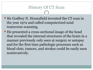
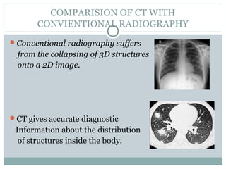
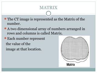
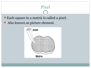
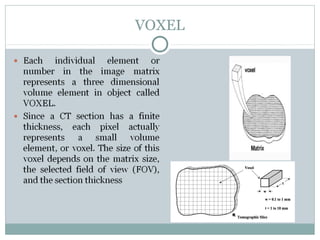
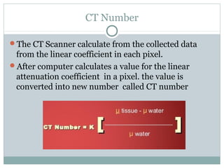
Sir Godfrey N. Hounsfield invented the CT scan in 1972, presenting the first cross-sectional image of the internal structures of the brain without surgery. CT works by reconstructing internal structures from multiple X-ray projections taken around an object at different angles. Compared to conventional radiography, CT provides more accurate diagnostic information by not collapsing 3D structures onto a 2D image. CT continues to advance with improvements such as faster scanning times, higher resolution images, and the ability to produce 3D volume images.