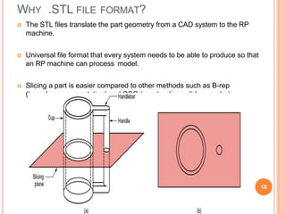
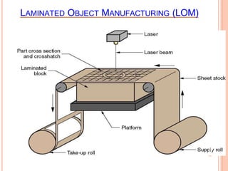
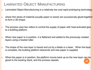
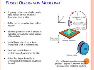
The document provides information on rapid prototyping and different rapid prototyping technologies. It begins with defining what a prototype is and why prototypes are developed. It then discusses the development of rapid prototyping, including manual, soft, and rapid prototyping phases. Key rapid prototyping technologies are described such as stereolithography, laminated object manufacturing, fused deposition modeling, and selective laser sintering. Applications and basic principles of rapid prototyping are also covered.

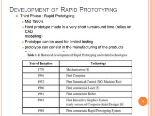


![LOM: companies, applications
Original technology developed by Helisys Inc.; Helisys acquired by
Corum.
1. Cubic Technologies Inc [www.cubictechnologies.com]
2. KIRA Corp, Japan [www.kiracorp.co.jp]
[source: Corum Inc] [source: KIRA corporation]
32](https://image.slidesharecdn.com/rapidprototyping-240326164731-b17d92b1/85/Rapid-Prototyping-lpu-mechanical-engineering-pptx-30-320.jpg)


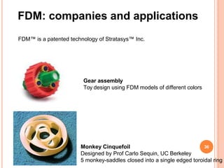


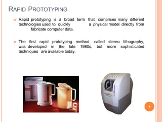
![SLS: companies and applications
First commercialized by Prof Carl Deckard (UT
Austin) Marketed by DTM Corp.
DTM acquired by 3Dsystems Inc.
1. 3D Systems™ Inc. (www.3Dsystems.com)
2.EOS GmbH, Munich, Germany.
[both examples, source: DTM inc.]
Plastic parts using SLS Metal mold using SLS, injection molded parts
42](https://image.slidesharecdn.com/rapidprototyping-240326164731-b17d92b1/85/Rapid-Prototyping-lpu-mechanical-engineering-pptx-40-320.jpg)

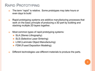
![3D Printing: companies, applications
1. Z-corporation [www.zcorp.com]
2. Soligen [www.soligen.com]
Engine manifold for GM racing car
Cast after Direct Shell Production Casting
[source: www.soligen.com]
45](https://image.slidesharecdn.com/rapidprototyping-240326164731-b17d92b1/85/Rapid-Prototyping-lpu-mechanical-engineering-pptx-43-320.jpg)


