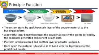
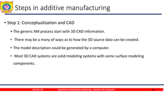
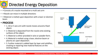
Sanjivani Rural Education Society’s
Sanjivani College of Engineering, Kopargaon-423 603
(An Autonomous Institute, Affiliated to Savitribai Phule Pune University, Pune)
NAAC ‘A’ Grade Accredited, ISO 9001:2015 Certified
Department of Mechanical Engineering
Gujrathi Sonam
Assistant Professor
Sanjivani College of Engineering, Kopargaon
E-mail : gujrathisonammech@sanjivani.org.in
Contact No: 8483874906
Subject :- Manufacturing Process I (MP I)
S.Y. B.Tech. Mechanical
Unit 6- Additive Mnufacturing
2
Contents
• Definition, need, raw materials, types of processes
• Photo polymerization
• Binder jetting, material extrusion
• Powder bed fusion
• Sheet lamination, direct energy deposition
• Limitations, strengths
• Programming methods.
Gujrathi S.M. Department Of Mechanical Engineering, Sanjivani COE, Kopargaon
3
Introduction
• The term Rapid Prototyping (or RP) is used to describe a process for rapidly
creating a system or part representation before final release or
commercialization.
• A recently formed Technical Committee within ASTM International agreed that
new terminology should be adopted.
• Recently adopted ASTM consensus standards now use the term Additive
Manufacturing.
• The basic principle of this technology is that a model, initially generated using a
3D Computer Aided Design (3D CAD) system, can be fabricated directly without
the need for process planning.
Gujrathi S.M. Department Of Mechanical Engineering, Sanjivani COE, Kopargaon
4
Introduction
• Technology that can make anything.
• Eliminates many constraints imposed by conventional manufacturing
• Leads to more market opportunities.
• Increased applications such as 3D faxing sender scans a 3D object in cross
sections and sends out the digital
• image in layers, and then the recipient receives the layered image and uses an
AM machine to fabricate the 3D object.
Gujrathi S.M. Department Of Mechanical Engineering, Sanjivani COE, Kopargaon
5
Definition of prototype
• A prototype is the first or original example of something that has been or will
be copied or developed; it is a model or preliminary version;
e.g.: A prototype supersonic aircraft.
or
• An approximation of a product (or system) or its components in some form
for a definite purpose in its implementation.
Gujrathi S.M. Department Of Mechanical Engineering, Sanjivani COE, Kopargaon
6
Prototype fundamentals
• The general definition of the prototype contains three aspects of interests:
(1) Implementation of the prototype; from the entire product itself to its sub-assemblies
and components,
(2) Form of the prototype; from a virtual prototype to a physical prototype
(3) Degree of the approximation of the prototype; from a very rough representation to
an exact replication of the product.
Gujrathi S.M. Department Of Mechanical Engineering, Sanjivani COE, Kopargaon
7
Often used terms
• Additive Manufacturing – Layer Manufacturing
• Additive Additive Manufacturing (AM)
• Additive Layer Manufacturing (ALM)
• Additive Digital Manufacturing (DM)
• Layer Layer Based Manufacturing
• Layer Oriented Manufacturing
• Layer Manufacturing
• Rapid Rapid Technology, Rapid Prototyping Rapid Tooling, Rapid Manufacturing
• Digital Digital Fabrication, Digital Mock-Up
• 3D Printing, 3D Modeling
• Direct Manufacturing, Direct Tooling
Gujrathi S.M. Department Of Mechanical Engineering, Sanjivani COE, Kopargaon
8
Additive Manufacturing – Layer Manufacturing
• “Additive Manufacturing” (AM) is a layer-based automated fabrication process
for making scaled 3-dimensional physical objects directly from 3D-CAD data
without using part-depending tools.
• It was originally called “3D Printing”.
• Additive manufacturing also refers to technologies that create objects, layer
by layer or sequential layering
Gujrathi S.M. Department Of Mechanical Engineering, Sanjivani COE, Kopargaon
9
Additive Manufacturing – Layer Manufacturing
• Additive manufacturing, also
known as 3D printing, rapid
prototyping or freeform
fabrication, is ‘the process of
joining materials to make
objects from 3D model data,
usually layer upon layer, as
opposed to subtractive
manufacturing methodologies’
such as machining.
Gujrathi S.M. Department Of Mechanical Engineering, Sanjivani COE, Kopargaon
10
Additive Manufacturing – Layer Manufacturing
• The process of joining materials to make objects from three dimensional (3D)
model data, usually layer by layer Commonly known as “3D printing”
• Manufacturing components with virtually no geometric limitations or tools.
• AM uses an additive process
• Design for manufacturing to manufacturing for design
• Distinguished from traditional subtractive machining techniques
Gujrathi S.M. Department Of Mechanical Engineering, Sanjivani COE, Kopargaon
11
The generic AM process
Gujrathi S.M. Department Of Mechanical Engineering, Sanjivani COE, Kopargaon
12
Principle Function
• The system starts by applying a thin layer of the powder material to the
building platform.
• A powerful laser beam then fuses the powder at exactly the points defined by
the computer-generated component design data.
• Platform is then lowered and another layer of powder is applied.
• Once again the material is fused so as to bond with the layer below at the
predefined points.
Gujrathi S.M. Department Of Mechanical Engineering, Sanjivani COE, Kopargaon
13
ADVANTAGES
• Freedom of design
• Complexity for free
• Potential elimination of tooling
• Lightweight design
• Elimination of production steps
Gujrathi S.M. Department Of Mechanical Engineering, Sanjivani COE, Kopargaon
14
DISADVANTAGES
• Slow build rates
• High production costs
• Considerable effort required for application design
• Discontinuous production process
• Limited component size.
Gujrathi S.M. Department Of Mechanical Engineering, Sanjivani COE, Kopargaon
15
Applications
• AM has been used across a diverse array of industries, including;
• Automotive
• Aerospace
• Biomedical
• Consumer goods and many others
Gujrathi S.M. Department Of Mechanical Engineering, Sanjivani COE, Kopargaon
16
Distinction between AM & CNC machining
Gujrathi S.M. Department Of Mechanical Engineering, Sanjivani COE, Kopargaon
17
Distinction between AM & CNC machining
• Materials
• Speed
• Ease of use
• Accuracy, Size limitations & Geometric Complexity
• Programming
• Cost
• Environmentally Friendly
Gujrathi S.M. Department Of Mechanical Engineering, Sanjivani COE, Kopargaon
18
Limitations of AM
• Material choice: Non weldable metals cannot be processed by additive
manufacturing and difficult-to-weld alloys require specific approaches.
• Material properties: Parts made by additive manufacturing tend to show
anisotropy in the Z axis (construction direction).
• The densities of 99.9% can be reached, there can be some residual internal
porosities.
• Mechanical properties are usually superior to cast parts but in general inferior
to wrought parts.
Gujrathi S.M. Department Of Mechanical Engineering, Sanjivani COE, Kopargaon
19
Steps in additive manufacturing
• Step 1: Conceptualization and CAD
• The generic AM process start with 3D CAD information.
• There may be a many of ways as to how the 3D source data can be created.
• The model description could be generated by a computer.
• Most 3D CAD systems are solid modeling systems with some surface modeling
components.
Gujrathi S.M. Department Of Mechanical Engineering, Sanjivani COE, Kopargaon
20
Steps in additive manufacturing
• Step 2: Conversion to STL
• The term STL was derived from STereoLithograhy.
• STL is a simple way of describing a CAD model in terms of its geometry alone.
• It works by removing any construction data, modeling history, etc., and
• approximating the surfaces of the model with a series of triangular facets.
• The minimum size of these triangles can be set within most CAD software and
• the objective is to ensure the models created do not show any obvious triangles on the
surface.
Gujrathi S.M. Department Of Mechanical Engineering, Sanjivani COE, Kopargaon
21
Steps in additive manufacturing
• Step 2: Conversion to STL
• STL is essentially a surface description, the corresponding triangles in the files
• must be pointing in the correct direction; (in other words, the surface normal vector
associated with the triangle must indicate which side of the triangle is outside vs.
inside the part).
• While most errors can be detected and rectified automatically, there may also be a
requirement for manual intervention.
Gujrathi S.M. Department Of Mechanical Engineering, Sanjivani COE, Kopargaon
22
Steps in additive manufacturing
• Step 3: Transfer to AM Machine and STL File Manipulation
• Once the STL file has been created, it can be sent directly to the target AM machine.
• Ideally, it should be possible to press a “print” button and the machine should build the
part straight away.
• However there may be a number of actions required prior to building the part.
• The first task would be to verify that the part is correct.
• AM system software normally has a visualization tool that allows the user to view and
manipulate the part.
Gujrathi S.M. Department Of Mechanical Engineering, Sanjivani COE, Kopargaon
23
Steps in additive manufacturing
• Step 3: Transfer to AM Machine and STL File Manipulation
• The user may wish to reposition the part or even change the orientation to allow it to
be built at a specific location within the machine.
• It is quite common to build more than one part in an AM machine at a time.
• This may be multiples of the same part (thus requiring a copy function) or completely
different STL files.
Gujrathi S.M. Department Of Mechanical Engineering, Sanjivani COE, Kopargaon
24
Steps in additive manufacturing
• Step 4: Machine Setup
• All AM machines will have at least some setup parameters that are specific to that
machine or process.
• Some machines are only designed to run perhaps one or two different materials and
with no variation in layer thickness or other build parameters.
• In the more complex cases to have default settings or save files from previously defined
setups to help speed up the machine setup process and to prevent mistakes.
• Normally, an incorrect setup procedure will still result in a part being built.
Gujrathi S.M. Department Of Mechanical Engineering, Sanjivani COE, Kopargaon
25
Steps in additive manufacturing
• Step 5: Build Setup
• The first few stages of the AM process are semi-automated tasks that may require
considerable manual control, interaction, and decision making.
• Once these steps are completed, the process switches to the computer controlled
building phase.
• All AM machines will have a similar sequence of layer control, using a height adjustable
platform, material deposition, and layer cross-section formation.
• All machines will repeat the process until either the build is complete or there is no
source material remaining.
Gujrathi S.M. Department Of Mechanical Engineering, Sanjivani COE, Kopargaon
26
Steps in additive manufacturing
• Step 6: Removal and Cleanup
• The output from the AM machine should be ready for use.
• More often the parts still require a significant amount of manual finishing before they
are ready for use.
• The part must be either separated from a build platform on which the part was
produced or removed from excess build material surrounding the part.
• Some AM processes use additional material other than that used to make the part itself
(secondary support materials).
Gujrathi S.M. Department Of Mechanical Engineering, Sanjivani COE, Kopargaon
27
Steps in additive manufacturing
• Step 7: Post Process
• Post-processing refers to the (usually manual) stages of finishing the parts for
application purposes.
• This may involve abrasive finishing, like polishing and sandpapering, or
application of coatings.
Gujrathi S.M. Department Of Mechanical Engineering, Sanjivani COE, Kopargaon
28
Steps in additive manufacturing
• Step 8: Application
• Following post-processing, parts are ready for use.
• Although parts may be made from similar materials to those available from other
manufacturing processes (like molding and casting), parts may not behave according to
standard material specifications.
• Some AM processes create parts with small voids or bubbles trapped inside them, which
could be the source for part failure under mechanical stress.
• Some processes may cause the material to degrade during build or for materials not to
bond, link, or crystallize in an optimum way.
Gujrathi S.M. Department Of Mechanical Engineering, Sanjivani COE, Kopargaon
29
AM Process
• 1) Vat Photopolymerisation/Steriolithography
• 2) Material Jetting
• 3) Binder jetting
• 4) Material extrusion
• 5) Powder bed fusion
• 6) Sheet lamination
• 7) Directed energy deposition
Gujrathi S.M. Department Of Mechanical Engineering, Sanjivani COE, Kopargaon
30
Vat photopolymerization/Steriolithography
• Laser beam traces a cross-section of the
part pattern on the surface of the liquid
resin
• SLA's elevator platform descends
• A resin-filled blade sweeps across the
cross section of the part, re-coating it
with fresh material
• Immersed in a chemical bath
• Stereolithography requires the use of
supporting structures
Gujrathi S.M. Department Of Mechanical Engineering, Sanjivani COE, Kopargaon
31
Material jetting
• • Drop on demand method
• • The print head is positioned above build
platform
• • Material is deposited from a nozzle which
moves horizontally across the build platform
• • Material layers are then cured or
hardened using ultraviolet (UV) light
• • Droplets of material solidify and make up
the first layer.
• • Platform descends
• • Good accuracy and surface finishes
Gujrathi S.M. Department Of Mechanical Engineering, Sanjivani COE, Kopargaon
32
Binder jetting
• • A glue or binder is jetted from an
inkjet style print head
• • Roller spreads a new layer of powder
on top of the previous
• layer
• • The subsequent layer is then printed
and is stitched to the
• previous layer by the jetted binder
• • The remaining loose powder in the
bed supports overhanging
• structures
Gujrathi S.M. Department Of Mechanical Engineering, Sanjivani COE, Kopargaon
33
Material Extrusion/FDM
• • Fuse deposition modelling (FDM)
• • Material is drawn through a nozzle, where
it is heated and is then deposited layer by
layer
• • First layer is built as nozzle deposits
material where required onto the cross
sectional area.
• • The following layers are added on top of
previous layers.
• • Layers are fused together upon deposition
as the material is in a melted state.
Gujrathi S.M. Department Of Mechanical Engineering, Sanjivani COE, Kopargaon
34
Powder Bed Fusion
• • Selective laser sintering (SLS)
• • Selective laser melting (SLM)
• • Electron beam melting (EBM)
• No support structures required
• PROCESS
• • A layer, typically 0.1mm thick of material is spread over the
build platform.
• • The SLS machine preheats the bulk powder material in the
powder bed
• • A laser fuses the first layer
• • A new layer of powder is spread.
• • Further layers or cross sections are fused and added.
• • The process repeats until the entire model is created.
Gujrathi S.M. Department Of Mechanical Engineering, Sanjivani COE, Kopargaon
35
Sheet Lamination
• • Metal sheets are used
• • Laser beam cuts the contour of
each layer
• • Glue activated by hot rollers
• PROCESS
• 1. The material is positioned in place on
the cutting bed.
• 2. The material is bonded in place, over
the previous layer, using the adhesive.
• 3. The required shape is then cut from
the layer, by laser or knife.
• 4. The next layer is added.
Gujrathi S.M. Department Of Mechanical Engineering, Sanjivani COE, Kopargaon
36
Directed Energy Deposition
• • Consists of a nozzle mounted on a multi axis arm
• • Nozzle can move in multiple directions
• • Material is melted upon deposition with a laser or electron
beam
• PROCESS
• 1. A4 or 5 axis arm with nozzle moves around a fixed
object.
• 2. Material is deposited from the nozzle onto existing
surfaces of the object.
• 3. Material is either provided in wire or powder form.
• 4. Material is melted using a laser, electron beam or
plasma arc upon deposition.
• 5. Further material is added layer by layer and solidifies,
creating or repairing new material features on the
existing object.
Gujrathi S.M. Department Of Mechanical Engineering, Sanjivani COE, Kopargaon
37Gujrathi S.M. Department Of Mechanical Engineering, Sanjivani COE, Kopargaon

Unit 6 additive mnufacturing

  • 1.
    Sanjivani Rural EducationSociety’s Sanjivani College of Engineering, Kopargaon-423 603 (An Autonomous Institute, Affiliated to Savitribai Phule Pune University, Pune) NAAC ‘A’ Grade Accredited, ISO 9001:2015 Certified Department of Mechanical Engineering Gujrathi Sonam Assistant Professor Sanjivani College of Engineering, Kopargaon E-mail : gujrathisonammech@sanjivani.org.in Contact No: 8483874906 Subject :- Manufacturing Process I (MP I) S.Y. B.Tech. Mechanical Unit 6- Additive Mnufacturing
  • 2.
    2 Contents • Definition, need,raw materials, types of processes • Photo polymerization • Binder jetting, material extrusion • Powder bed fusion • Sheet lamination, direct energy deposition • Limitations, strengths • Programming methods. Gujrathi S.M. Department Of Mechanical Engineering, Sanjivani COE, Kopargaon
  • 3.
    3 Introduction • The termRapid Prototyping (or RP) is used to describe a process for rapidly creating a system or part representation before final release or commercialization. • A recently formed Technical Committee within ASTM International agreed that new terminology should be adopted. • Recently adopted ASTM consensus standards now use the term Additive Manufacturing. • The basic principle of this technology is that a model, initially generated using a 3D Computer Aided Design (3D CAD) system, can be fabricated directly without the need for process planning. Gujrathi S.M. Department Of Mechanical Engineering, Sanjivani COE, Kopargaon
  • 4.
    4 Introduction • Technology thatcan make anything. • Eliminates many constraints imposed by conventional manufacturing • Leads to more market opportunities. • Increased applications such as 3D faxing sender scans a 3D object in cross sections and sends out the digital • image in layers, and then the recipient receives the layered image and uses an AM machine to fabricate the 3D object. Gujrathi S.M. Department Of Mechanical Engineering, Sanjivani COE, Kopargaon
  • 5.
    5 Definition of prototype •A prototype is the first or original example of something that has been or will be copied or developed; it is a model or preliminary version; e.g.: A prototype supersonic aircraft. or • An approximation of a product (or system) or its components in some form for a definite purpose in its implementation. Gujrathi S.M. Department Of Mechanical Engineering, Sanjivani COE, Kopargaon
  • 6.
    6 Prototype fundamentals • Thegeneral definition of the prototype contains three aspects of interests: (1) Implementation of the prototype; from the entire product itself to its sub-assemblies and components, (2) Form of the prototype; from a virtual prototype to a physical prototype (3) Degree of the approximation of the prototype; from a very rough representation to an exact replication of the product. Gujrathi S.M. Department Of Mechanical Engineering, Sanjivani COE, Kopargaon
  • 7.
    7 Often used terms •Additive Manufacturing – Layer Manufacturing • Additive Additive Manufacturing (AM) • Additive Layer Manufacturing (ALM) • Additive Digital Manufacturing (DM) • Layer Layer Based Manufacturing • Layer Oriented Manufacturing • Layer Manufacturing • Rapid Rapid Technology, Rapid Prototyping Rapid Tooling, Rapid Manufacturing • Digital Digital Fabrication, Digital Mock-Up • 3D Printing, 3D Modeling • Direct Manufacturing, Direct Tooling Gujrathi S.M. Department Of Mechanical Engineering, Sanjivani COE, Kopargaon
  • 8.
    8 Additive Manufacturing –Layer Manufacturing • “Additive Manufacturing” (AM) is a layer-based automated fabrication process for making scaled 3-dimensional physical objects directly from 3D-CAD data without using part-depending tools. • It was originally called “3D Printing”. • Additive manufacturing also refers to technologies that create objects, layer by layer or sequential layering Gujrathi S.M. Department Of Mechanical Engineering, Sanjivani COE, Kopargaon
  • 9.
    9 Additive Manufacturing –Layer Manufacturing • Additive manufacturing, also known as 3D printing, rapid prototyping or freeform fabrication, is ‘the process of joining materials to make objects from 3D model data, usually layer upon layer, as opposed to subtractive manufacturing methodologies’ such as machining. Gujrathi S.M. Department Of Mechanical Engineering, Sanjivani COE, Kopargaon
  • 10.
    10 Additive Manufacturing –Layer Manufacturing • The process of joining materials to make objects from three dimensional (3D) model data, usually layer by layer Commonly known as “3D printing” • Manufacturing components with virtually no geometric limitations or tools. • AM uses an additive process • Design for manufacturing to manufacturing for design • Distinguished from traditional subtractive machining techniques Gujrathi S.M. Department Of Mechanical Engineering, Sanjivani COE, Kopargaon
  • 11.
    11 The generic AMprocess Gujrathi S.M. Department Of Mechanical Engineering, Sanjivani COE, Kopargaon
  • 12.
    12 Principle Function • Thesystem starts by applying a thin layer of the powder material to the building platform. • A powerful laser beam then fuses the powder at exactly the points defined by the computer-generated component design data. • Platform is then lowered and another layer of powder is applied. • Once again the material is fused so as to bond with the layer below at the predefined points. Gujrathi S.M. Department Of Mechanical Engineering, Sanjivani COE, Kopargaon
  • 13.
    13 ADVANTAGES • Freedom ofdesign • Complexity for free • Potential elimination of tooling • Lightweight design • Elimination of production steps Gujrathi S.M. Department Of Mechanical Engineering, Sanjivani COE, Kopargaon
  • 14.
    14 DISADVANTAGES • Slow buildrates • High production costs • Considerable effort required for application design • Discontinuous production process • Limited component size. Gujrathi S.M. Department Of Mechanical Engineering, Sanjivani COE, Kopargaon
  • 15.
    15 Applications • AM hasbeen used across a diverse array of industries, including; • Automotive • Aerospace • Biomedical • Consumer goods and many others Gujrathi S.M. Department Of Mechanical Engineering, Sanjivani COE, Kopargaon
  • 16.
    16 Distinction between AM& CNC machining Gujrathi S.M. Department Of Mechanical Engineering, Sanjivani COE, Kopargaon
  • 17.
    17 Distinction between AM& CNC machining • Materials • Speed • Ease of use • Accuracy, Size limitations & Geometric Complexity • Programming • Cost • Environmentally Friendly Gujrathi S.M. Department Of Mechanical Engineering, Sanjivani COE, Kopargaon
  • 18.
    18 Limitations of AM •Material choice: Non weldable metals cannot be processed by additive manufacturing and difficult-to-weld alloys require specific approaches. • Material properties: Parts made by additive manufacturing tend to show anisotropy in the Z axis (construction direction). • The densities of 99.9% can be reached, there can be some residual internal porosities. • Mechanical properties are usually superior to cast parts but in general inferior to wrought parts. Gujrathi S.M. Department Of Mechanical Engineering, Sanjivani COE, Kopargaon
  • 19.
    19 Steps in additivemanufacturing • Step 1: Conceptualization and CAD • The generic AM process start with 3D CAD information. • There may be a many of ways as to how the 3D source data can be created. • The model description could be generated by a computer. • Most 3D CAD systems are solid modeling systems with some surface modeling components. Gujrathi S.M. Department Of Mechanical Engineering, Sanjivani COE, Kopargaon
  • 20.
    20 Steps in additivemanufacturing • Step 2: Conversion to STL • The term STL was derived from STereoLithograhy. • STL is a simple way of describing a CAD model in terms of its geometry alone. • It works by removing any construction data, modeling history, etc., and • approximating the surfaces of the model with a series of triangular facets. • The minimum size of these triangles can be set within most CAD software and • the objective is to ensure the models created do not show any obvious triangles on the surface. Gujrathi S.M. Department Of Mechanical Engineering, Sanjivani COE, Kopargaon
  • 21.
    21 Steps in additivemanufacturing • Step 2: Conversion to STL • STL is essentially a surface description, the corresponding triangles in the files • must be pointing in the correct direction; (in other words, the surface normal vector associated with the triangle must indicate which side of the triangle is outside vs. inside the part). • While most errors can be detected and rectified automatically, there may also be a requirement for manual intervention. Gujrathi S.M. Department Of Mechanical Engineering, Sanjivani COE, Kopargaon
  • 22.
    22 Steps in additivemanufacturing • Step 3: Transfer to AM Machine and STL File Manipulation • Once the STL file has been created, it can be sent directly to the target AM machine. • Ideally, it should be possible to press a “print” button and the machine should build the part straight away. • However there may be a number of actions required prior to building the part. • The first task would be to verify that the part is correct. • AM system software normally has a visualization tool that allows the user to view and manipulate the part. Gujrathi S.M. Department Of Mechanical Engineering, Sanjivani COE, Kopargaon
  • 23.
    23 Steps in additivemanufacturing • Step 3: Transfer to AM Machine and STL File Manipulation • The user may wish to reposition the part or even change the orientation to allow it to be built at a specific location within the machine. • It is quite common to build more than one part in an AM machine at a time. • This may be multiples of the same part (thus requiring a copy function) or completely different STL files. Gujrathi S.M. Department Of Mechanical Engineering, Sanjivani COE, Kopargaon
  • 24.
    24 Steps in additivemanufacturing • Step 4: Machine Setup • All AM machines will have at least some setup parameters that are specific to that machine or process. • Some machines are only designed to run perhaps one or two different materials and with no variation in layer thickness or other build parameters. • In the more complex cases to have default settings or save files from previously defined setups to help speed up the machine setup process and to prevent mistakes. • Normally, an incorrect setup procedure will still result in a part being built. Gujrathi S.M. Department Of Mechanical Engineering, Sanjivani COE, Kopargaon
  • 25.
    25 Steps in additivemanufacturing • Step 5: Build Setup • The first few stages of the AM process are semi-automated tasks that may require considerable manual control, interaction, and decision making. • Once these steps are completed, the process switches to the computer controlled building phase. • All AM machines will have a similar sequence of layer control, using a height adjustable platform, material deposition, and layer cross-section formation. • All machines will repeat the process until either the build is complete or there is no source material remaining. Gujrathi S.M. Department Of Mechanical Engineering, Sanjivani COE, Kopargaon
  • 26.
    26 Steps in additivemanufacturing • Step 6: Removal and Cleanup • The output from the AM machine should be ready for use. • More often the parts still require a significant amount of manual finishing before they are ready for use. • The part must be either separated from a build platform on which the part was produced or removed from excess build material surrounding the part. • Some AM processes use additional material other than that used to make the part itself (secondary support materials). Gujrathi S.M. Department Of Mechanical Engineering, Sanjivani COE, Kopargaon
  • 27.
    27 Steps in additivemanufacturing • Step 7: Post Process • Post-processing refers to the (usually manual) stages of finishing the parts for application purposes. • This may involve abrasive finishing, like polishing and sandpapering, or application of coatings. Gujrathi S.M. Department Of Mechanical Engineering, Sanjivani COE, Kopargaon
  • 28.
    28 Steps in additivemanufacturing • Step 8: Application • Following post-processing, parts are ready for use. • Although parts may be made from similar materials to those available from other manufacturing processes (like molding and casting), parts may not behave according to standard material specifications. • Some AM processes create parts with small voids or bubbles trapped inside them, which could be the source for part failure under mechanical stress. • Some processes may cause the material to degrade during build or for materials not to bond, link, or crystallize in an optimum way. Gujrathi S.M. Department Of Mechanical Engineering, Sanjivani COE, Kopargaon
  • 29.
    29 AM Process • 1)Vat Photopolymerisation/Steriolithography • 2) Material Jetting • 3) Binder jetting • 4) Material extrusion • 5) Powder bed fusion • 6) Sheet lamination • 7) Directed energy deposition Gujrathi S.M. Department Of Mechanical Engineering, Sanjivani COE, Kopargaon
  • 30.
    30 Vat photopolymerization/Steriolithography • Laserbeam traces a cross-section of the part pattern on the surface of the liquid resin • SLA's elevator platform descends • A resin-filled blade sweeps across the cross section of the part, re-coating it with fresh material • Immersed in a chemical bath • Stereolithography requires the use of supporting structures Gujrathi S.M. Department Of Mechanical Engineering, Sanjivani COE, Kopargaon
  • 31.
    31 Material jetting • •Drop on demand method • • The print head is positioned above build platform • • Material is deposited from a nozzle which moves horizontally across the build platform • • Material layers are then cured or hardened using ultraviolet (UV) light • • Droplets of material solidify and make up the first layer. • • Platform descends • • Good accuracy and surface finishes Gujrathi S.M. Department Of Mechanical Engineering, Sanjivani COE, Kopargaon
  • 32.
    32 Binder jetting • •A glue or binder is jetted from an inkjet style print head • • Roller spreads a new layer of powder on top of the previous • layer • • The subsequent layer is then printed and is stitched to the • previous layer by the jetted binder • • The remaining loose powder in the bed supports overhanging • structures Gujrathi S.M. Department Of Mechanical Engineering, Sanjivani COE, Kopargaon
  • 33.
    33 Material Extrusion/FDM • •Fuse deposition modelling (FDM) • • Material is drawn through a nozzle, where it is heated and is then deposited layer by layer • • First layer is built as nozzle deposits material where required onto the cross sectional area. • • The following layers are added on top of previous layers. • • Layers are fused together upon deposition as the material is in a melted state. Gujrathi S.M. Department Of Mechanical Engineering, Sanjivani COE, Kopargaon
  • 34.
    34 Powder Bed Fusion •• Selective laser sintering (SLS) • • Selective laser melting (SLM) • • Electron beam melting (EBM) • No support structures required • PROCESS • • A layer, typically 0.1mm thick of material is spread over the build platform. • • The SLS machine preheats the bulk powder material in the powder bed • • A laser fuses the first layer • • A new layer of powder is spread. • • Further layers or cross sections are fused and added. • • The process repeats until the entire model is created. Gujrathi S.M. Department Of Mechanical Engineering, Sanjivani COE, Kopargaon
  • 35.
    35 Sheet Lamination • •Metal sheets are used • • Laser beam cuts the contour of each layer • • Glue activated by hot rollers • PROCESS • 1. The material is positioned in place on the cutting bed. • 2. The material is bonded in place, over the previous layer, using the adhesive. • 3. The required shape is then cut from the layer, by laser or knife. • 4. The next layer is added. Gujrathi S.M. Department Of Mechanical Engineering, Sanjivani COE, Kopargaon
  • 36.
    36 Directed Energy Deposition •• Consists of a nozzle mounted on a multi axis arm • • Nozzle can move in multiple directions • • Material is melted upon deposition with a laser or electron beam • PROCESS • 1. A4 or 5 axis arm with nozzle moves around a fixed object. • 2. Material is deposited from the nozzle onto existing surfaces of the object. • 3. Material is either provided in wire or powder form. • 4. Material is melted using a laser, electron beam or plasma arc upon deposition. • 5. Further material is added layer by layer and solidifies, creating or repairing new material features on the existing object. Gujrathi S.M. Department Of Mechanical Engineering, Sanjivani COE, Kopargaon
  • 37.
    37Gujrathi S.M. DepartmentOf Mechanical Engineering, Sanjivani COE, Kopargaon