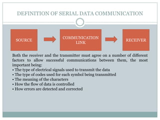
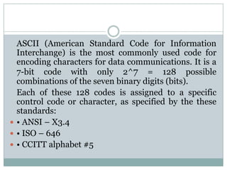
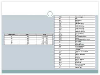
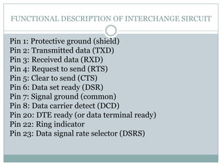
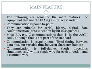
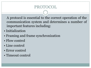
Serial Data Communication
                   MADE BY:

         ARNOVIA CHRISTINE SABATIANA
              MARTHA MAULINA
           RIZALDI SATRIA NUGRAHA

          POLITEKNIK NEGERI BANDUNG
REFRIGERATION AND AIR CONDITIONING ENGINEERING
MIND MAP
DEFINITION OF SERIAL DATA COMMUNICATION


                           COMMUNICATION
 SOURCE                                                      RECEIVER
                               LINK


Both the receiver and the transmitter must agree on a number of different
factors to allow successful communications between them, the most
important being:
• The type of electrical signals used to transmit the data
• The type of codes used for each symbol being transmitted
• The meaning of the characters
• How the flow of data is controlled
• How errors are detected and corrected
TRANSMISSION MODE
CODING OF MESSAGE

Encoding is the process of converting the message
data into a standard binary code for transfer over the
data communications link. The number of bits in a
code determines the total number of unique
characters that are possible.
ASCII (American Standard Code for Information
  Interchange) is the most commonly used code for
  encoding characters for data communications. It is a
  7-bit code with only 2^7 = 128 possible
  combinations of the seven binary digits (bits).
  Each of these 128 codes is assigned to a specific
  control code or character, as specified by the these
  standards:
 • ANSI – X3.4
 • ISO – 646
 • CCITT alphabet #5
FORMAT OF DATA COMMUNICATION MESSAGE


Data is usually arranged in a particular format, with additional information
added so that the message can be effectively transmitted and understood at the
receiving end. In summary, the optional settings for asynchronous
transmission of characters are:
• Start bits 1
• Data bits 5, 6, 7, 8
• Parity bits even, odd, mark, space or none
• Stop bits 1, l½ or 2
 As there cannot be half a bit, 1½-stop bits means that the mark length is 50%
longer than for one stop bit.
DATA TRANSMISSION SPEED

    The maximum rate at which data can be transferred from
    the source to the receiver on a com-munications interface
    depends on a number of factors:
   • Type and complexity of the circuitry at each end
    (interface)
   • Communication link (twisted-pair, coaxial cable, radio
    etc)
   • Distance between the sender and receiver
   • Amount of data being transferred
   • The overhead associated with the data transfer
   • The acceptable rate of error
RS-232-C INTERFACE STANDARD

   In telecommunications, RS-232 is the traditional name
   for a series of standards for serial binary single-
   ended data and control signals connecting between
   a DTE (Data Terminal Equipment) and a DCE (Data
   Circuit-terminating Equipment). It is commonly used
   in computer serial ports.
   The EIA-232 standard consists of three major
   components, which define:
• Electrical signal characteristics
• Interface mechanical characteristics
• Functional description of the interchange circuits
ELECTRICAL
SIGNAL
CHARACTERISTIC

At the RS-232 receiver
the following signal
voltage levels are
defined:

• +3 V to +25 V for
transmission of logic 0

• –3 V to –25 V for
transmission of logic 1
                          In practice, many EIA-232 transmitters operate very
• +3 V to –3 V for an     lose to their margin of safety, e.g. at +7 and –7 volts.
undefined logic level     This can be acceptable for short cable runs, where it is
                          hoped that there will be no voltage problems.
                          Unfortunately, increased error rates can be expected at
                          the receiver because of induced external interference
                          voltages.
INTERFACE
MECHANICAL
CHARACTERISTIC

While       this      pin
configuration is likely to
be     adhered to by
manufacturers at the
computers
communications
interface, it is possible
(and often likely) that
the data receive and
transmit      lines    on
remote       stand-alone
systems are on different
pins of the DB-9
connector.
FUNCTIONAL DESCRIPTION OF INTERCHANGE SIRCUIT


Pin 1: Protective ground (shield)
Pin 2: Transmitted data (TXD)
Pin 3: Received data (RXD)
Pin 4: Request to send (RTS)
Pin 5: Clear to send (CTS)
Pin 6: Data set ready (DSR)
Pin 7: Signal ground (common)
Pin 8: Data carrier detect (DCD)
Pin 20: DTE ready (or data terminal ready)
Pin 22: Ring indicator
Pin 23: Data signal rate selector (DSRS)
MAIN FEATURE

    The following are some of the main features             of
    equipment that use the EIA-232 interface standard:
   Communication is point-to-point
   They are suitable for serial, binary, digital, data
    communication (data is sent bit by bit in sequence)
   Most EIA-232-C communications data is in the ASCII
    code, although that is not part of the standard
   Communication is asynchronous (fixed timing between
    data bits, but variable time between character frames)
   Communication is full-duplex (both directions
    simultaneously) with a single wire for each direction and
    a common wire
RS-485 INTERFACE STANDARD

  The EIA RS-485 is the most versatile of the EIA
  standards, and is an expansion of the RS-422 standard.
  The RS-485 standard was designed for two-wire, half
  duplex, balanced multidrop communications, and allows
  up to 32 line drivers and 32 line receivers on the same
  line.
  RS-485 provides reliable serial communications for:
• Distances of up to 1200 m
• Data rates of up to 10 Mbps
• Up to 32 line drivers permitted on the same line
• Up to 32 line receivers permitted on the same line
RS-485
REPEATER
The repeater is a two-
port device that re-
transmits data received
on one side, at full
voltage levels, to the
network on the other
side.
COMPARISON BETWEEN TWO TYPE
PROTOCOL

  A protocol is essential to the correct operation of the
  communication system and determines a number of
  important features including:
• Initialization
• Framing and frame synchronization
• Flow control
• Line control
• Error control
• Timeout control
FLOW CONTROL PROTOCOL

  Cooperative flow control, in which the transmitter
  and receiver operate under a common set of rules, is
  called a flow control protocol. Below are described
  the two most popular flow control protocols.
 Character flow protocols (XON/XOFF)
 Whole line protocols (ETX/ACK)
ASCII BASED
PROTOCOL
The ASCII protocol is
normally only used for
slow systems with one
master talking to a         A simple command/response ASCII protocol, used
limited     number     of   for communications between a personal computer
slaves. ASCII protocols     and a digital transmitter is shown above.
are also popular for
stand-alone
instruments where a
serial interface has been
added, with no major
design changes, to the
existing system.
A variation of the short
form command and
response messages is
their      long    form
equivalents. To ensure
greater         message
integrity, and increase
reliability, long form
messages are included
with a block checksum
at the end of the
message.
ERROR DETECTION

  There are three popular forms of error checking used
  in many protocols. These are, in order of increasing
  error-detecting capability:
• Character redundancy checks
• Block redundancy checks
• Cyclic redundancy checks
TROUBLESHOOTING

  When trouble shooting a serial data communications
  interface, a logical approach needs to be followed, to
  avoid wasting many frustrating hours trying to find
  the problem. A procedure similar to that outlined
  below is recommended:
• Check the basic parameters
• Identify which is DTE or DCE
• Clarify the needs of the hardware handshaking
• Check the actual protocol used
When a data communication link won’t work, the
    following five very useful devices can be used to
    assist in analyzing the problem:
   A Breakout Box
   Null Modem
   Loop Back Plug
   PC based protocol analyzer (including software)

Serial Data Communication

  • 1.
    Serial Data Communication MADE BY: ARNOVIA CHRISTINE SABATIANA MARTHA MAULINA RIZALDI SATRIA NUGRAHA POLITEKNIK NEGERI BANDUNG REFRIGERATION AND AIR CONDITIONING ENGINEERING
  • 2.
  • 3.
    DEFINITION OF SERIALDATA COMMUNICATION COMMUNICATION SOURCE RECEIVER LINK Both the receiver and the transmitter must agree on a number of different factors to allow successful communications between them, the most important being: • The type of electrical signals used to transmit the data • The type of codes used for each symbol being transmitted • The meaning of the characters • How the flow of data is controlled • How errors are detected and corrected
  • 4.
  • 5.
    CODING OF MESSAGE Encodingis the process of converting the message data into a standard binary code for transfer over the data communications link. The number of bits in a code determines the total number of unique characters that are possible.
  • 6.
    ASCII (American StandardCode for Information Interchange) is the most commonly used code for encoding characters for data communications. It is a 7-bit code with only 2^7 = 128 possible combinations of the seven binary digits (bits). Each of these 128 codes is assigned to a specific control code or character, as specified by the these standards:  • ANSI – X3.4  • ISO – 646  • CCITT alphabet #5
  • 9.
    FORMAT OF DATACOMMUNICATION MESSAGE Data is usually arranged in a particular format, with additional information added so that the message can be effectively transmitted and understood at the receiving end. In summary, the optional settings for asynchronous transmission of characters are: • Start bits 1 • Data bits 5, 6, 7, 8 • Parity bits even, odd, mark, space or none • Stop bits 1, l½ or 2 As there cannot be half a bit, 1½-stop bits means that the mark length is 50% longer than for one stop bit.
  • 10.
    DATA TRANSMISSION SPEED The maximum rate at which data can be transferred from the source to the receiver on a com-munications interface depends on a number of factors:  • Type and complexity of the circuitry at each end (interface)  • Communication link (twisted-pair, coaxial cable, radio etc)  • Distance between the sender and receiver  • Amount of data being transferred  • The overhead associated with the data transfer  • The acceptable rate of error
  • 11.
    RS-232-C INTERFACE STANDARD In telecommunications, RS-232 is the traditional name for a series of standards for serial binary single- ended data and control signals connecting between a DTE (Data Terminal Equipment) and a DCE (Data Circuit-terminating Equipment). It is commonly used in computer serial ports. The EIA-232 standard consists of three major components, which define: • Electrical signal characteristics • Interface mechanical characteristics • Functional description of the interchange circuits
  • 12.
    ELECTRICAL SIGNAL CHARACTERISTIC At the RS-232receiver the following signal voltage levels are defined: • +3 V to +25 V for transmission of logic 0 • –3 V to –25 V for transmission of logic 1 In practice, many EIA-232 transmitters operate very • +3 V to –3 V for an lose to their margin of safety, e.g. at +7 and –7 volts. undefined logic level This can be acceptable for short cable runs, where it is hoped that there will be no voltage problems. Unfortunately, increased error rates can be expected at the receiver because of induced external interference voltages.
  • 13.
    INTERFACE MECHANICAL CHARACTERISTIC While this pin configuration is likely to be adhered to by manufacturers at the computers communications interface, it is possible (and often likely) that the data receive and transmit lines on remote stand-alone systems are on different pins of the DB-9 connector.
  • 14.
    FUNCTIONAL DESCRIPTION OFINTERCHANGE SIRCUIT Pin 1: Protective ground (shield) Pin 2: Transmitted data (TXD) Pin 3: Received data (RXD) Pin 4: Request to send (RTS) Pin 5: Clear to send (CTS) Pin 6: Data set ready (DSR) Pin 7: Signal ground (common) Pin 8: Data carrier detect (DCD) Pin 20: DTE ready (or data terminal ready) Pin 22: Ring indicator Pin 23: Data signal rate selector (DSRS)
  • 15.
    MAIN FEATURE The following are some of the main features of equipment that use the EIA-232 interface standard:  Communication is point-to-point  They are suitable for serial, binary, digital, data communication (data is sent bit by bit in sequence)  Most EIA-232-C communications data is in the ASCII code, although that is not part of the standard  Communication is asynchronous (fixed timing between data bits, but variable time between character frames)  Communication is full-duplex (both directions simultaneously) with a single wire for each direction and a common wire
  • 16.
    RS-485 INTERFACE STANDARD The EIA RS-485 is the most versatile of the EIA standards, and is an expansion of the RS-422 standard. The RS-485 standard was designed for two-wire, half duplex, balanced multidrop communications, and allows up to 32 line drivers and 32 line receivers on the same line. RS-485 provides reliable serial communications for: • Distances of up to 1200 m • Data rates of up to 10 Mbps • Up to 32 line drivers permitted on the same line • Up to 32 line receivers permitted on the same line
  • 17.
    RS-485 REPEATER The repeater isa two- port device that re- transmits data received on one side, at full voltage levels, to the network on the other side.
  • 18.
  • 19.
    PROTOCOL Aprotocol is essential to the correct operation of the communication system and determines a number of important features including: • Initialization • Framing and frame synchronization • Flow control • Line control • Error control • Timeout control
  • 20.
    FLOW CONTROL PROTOCOL Cooperative flow control, in which the transmitter and receiver operate under a common set of rules, is called a flow control protocol. Below are described the two most popular flow control protocols.  Character flow protocols (XON/XOFF)  Whole line protocols (ETX/ACK)
  • 21.
    ASCII BASED PROTOCOL The ASCIIprotocol is normally only used for slow systems with one master talking to a A simple command/response ASCII protocol, used limited number of for communications between a personal computer slaves. ASCII protocols and a digital transmitter is shown above. are also popular for stand-alone instruments where a serial interface has been added, with no major design changes, to the existing system.
  • 22.
    A variation ofthe short form command and response messages is their long form equivalents. To ensure greater message integrity, and increase reliability, long form messages are included with a block checksum at the end of the message.
  • 23.
    ERROR DETECTION There are three popular forms of error checking used in many protocols. These are, in order of increasing error-detecting capability: • Character redundancy checks • Block redundancy checks • Cyclic redundancy checks
  • 24.
    TROUBLESHOOTING Whentrouble shooting a serial data communications interface, a logical approach needs to be followed, to avoid wasting many frustrating hours trying to find the problem. A procedure similar to that outlined below is recommended: • Check the basic parameters • Identify which is DTE or DCE • Clarify the needs of the hardware handshaking • Check the actual protocol used
  • 25.
    When a datacommunication link won’t work, the following five very useful devices can be used to assist in analyzing the problem:  A Breakout Box  Null Modem  Loop Back Plug  PC based protocol analyzer (including software)