Downloaded 775 times
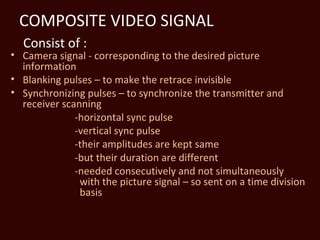
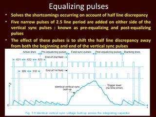

1. The composite video signal contains the camera signal, blanking pulses, and synchronizing pulses. 2. Horizontal and vertical synchronizing pulses are added on a time division basis and have different durations but the same amplitude. 3. Equalizing pulses are added to the vertical synchronizing pulses to ensure the vertical oscillator is triggered at the proper instant for each field.