SlideShare a Scribd company logo
INTRODUCTION
The process of changing some characteristic (e.g. amplitude, frequency, or phase) of
carrier wave in accordance with the intensity of a signal is known as Modulation. Is the process of
varying one or more properties of a high frequency periodic waveform, called the carrier signal,
with respect to a modulating signal. This is done in a similar fashion as a musician may modulate
a tone (a periodic waveform) from a musical instrument by varying its volume, timing and pitch.
The three key parameters of a periodic waveform are its amplitude ("volume"), its phase
("timing") and its frequency ("pitch"), all of which can be modified in accordance with a low
frequency signal to obtain the modulated signal. Typically a high-frequency sinusoid waveform
is used as carrier signal, but a square wave pulse train may also occur.
Modulation is a process of mixing a signal with a sinusoid to produce a new signal. This
new signal, conceivably, will have certain benefits of an un-modulated signal, especially during
transmission. If we look at a general function for a sinusoid:
f(t) = Asin(ωt + φ)
we can see that this sinusoid has 3 parameters that can be altered, to affect the shape of the
graph. The first term, A, is called the magnitude, or amplitude of the sinusoid. The next term, ω
is known as the frequency, and the last term, φ is known as the phase angle. All 3 parameters can
be altered to transmit data.
The sinusoidal signal that is used in the modulation is known as the carrier signal, or simply
"the carrier". The signal that is being modulated is known as the "data signal". It is important to
notice that a simple sinusoidal carrier contains no information of it's own.
In other words we can say that modulation is used because the some data signals are not
always suitable for direct transmission, but the modulated signal may be more suitable
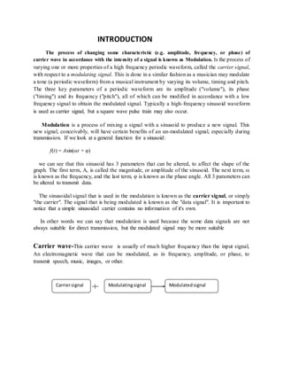
Carrier wave-This carrier wave is usually of much higher frequency than the input signal,
An electromagnetic wave that can be modulated, as in frequency, amplitude, or phase, to
transmit speech, music, images, or other.
Carriersignal Modulatingsignal Modulatedsignal
Non-sinusoidal modulation-
A sine wave at one frequency can separated from a sine wave at another frequency (or a cosine
wave at the same frequency) because the two signals are "orthogonal.
There are other sets of signals, such that every signal in the set is orthogonal to every other signal
in the set. A simple orthogonal set is time multiplexed division (TDM) -- only one transmitter is
active at any one time.
Other more complicated sets of orthogonal waveforms -- Walsh codes and various pseudonoise
codes such as Gold codes and maximum length sequences -- are also used in some
communication systems. The process of combining these waveforms with data signals is
sometimes called "modulation", because it is so very similar to the way modulation combines
sine waves are with data signals.
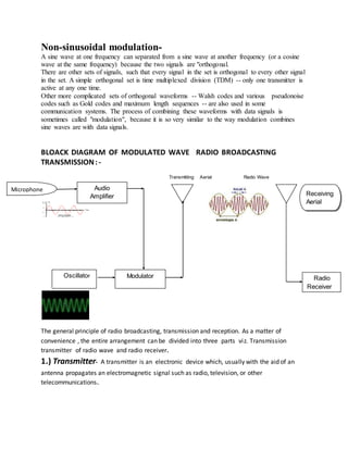
BLOACK DIAGRAM OF MODULATED WAVE RADIO BROADCASTING
TRANSMISSION: -
Transmitting Aerial Radio Wave
The general principle of radio broadcasting, transmission and reception. As a matter of
convenience , the entire arrangement can be divided into three parts viz. Transmission
transmitter of radio wave and radio receiver.
1.) Transmitter- A transmitter is an electronic device which, usually with the aid of an
antenna propagates an electromagnetic signal such as radio, television, or other
telecommunications.
Audio
Amplifier
Oscillator Modulator Radio
Receiver
Microphone
Receiving
Aerial
2.) Microphone- A microphone (colloquially called a mic or mike; both pronounced is an
acoustic-to-electric transducer or sensor that converts sound into an electrical signal. In 1876,
Emile Berliner invented the first microphone used as a telephone voice transmitter.
Microphones are used in many applications such as telephones, tape recorders, karaoke
systems, hearing aids, motion picture production, live and recorded audio engineering, FRS
radios, megaphones, in radio and television broadcasting and in computers for recording voice,
speech recognition, VoIP, and for non-acoustic purposes such as ultrasonic checking or knock
sensors.
3.) Audio amplifier-An audio amplifier is an electronic amplifier that amplifies low-power
audio signals (signals composed primarily of frequencies between 20 - 20 000 Hz, the human
range of hearing) to a level suitable for driving loudspeakers and is the final stage in a typical
audio playback chain
4.) Electronic oscillator-An electronic oscillator is an electronic circuit that produces a
repetitive electronic signal, often a sine wave or a square wave. They are widely used in
innumerable electronic devices. Common examples of signals generated by oscillators include
signals broadcast by radio and television transmitters, clock signals that regulate computers and
quartz clocks, and the sounds produced by electronic beepers and video games. A low-
frequency oscillator (LFO) is an electronic oscillator that generates an AC waveform at a
frequency below ≈20 Hz. This term is typically used in the field of audio synthesizers, to
distinguish it from an audio frequency oscillator.
5.) MODULATOR- The transmitter stage that supplies the modulating signal to modulated
amplifier stage or triggers, A device used to modulate an electromagnetic wave. Addition of
information (or the signal) to an electronic or optical signal carrier.
6.) Transmission of radio waves-Radio is the transmission of signals by modulation
of electromagnetic waves with frequencies below those of visible light. Electromagnetic
radiation travels by means of oscillating electromagnetic fields that pass through the air and the
vacuum of space. Information is carried by systematically changing (modulating) some property
of the radiated waves, such as amplitude, frequency, phase, or pulse width. When radio waves
pass an electrical conductor, the oscillating fields induce an alternating current in the
conductor. This can be detected and transformed into sound or other signals that carry
information.
7.) Radio receiver- A radio receiver is an electronic circuit that receives its input from an
antenna, uses electronic filters to separate a wanted radio signal from all other signals picked
up by this antenna, amplifies it to a level suitable for further processing, and finally converts
through demodulation and decoding the signal into a form usable for the consumer, such as
sound, pictures, digital data, measurement values, navigational positions, etc.[
NEED FOR MODULATION
Practical Antenna Length (L)
When free space is the communication channel, antennas radiate and receiver the signal . Theory
shows that the antennas operate effective only when their dimensions are of the order of the
magnitude of wavelength of the signal being transmitted.
The audio frequencies range from 20 Hz to 20 kHz. Suppose a frequency of 20 kHz is to be
radiated directly into space. For this,
This is too long antenna to be constructed practically. So, it is impracticable to radiate audio
signal directly into space.
Let usnow calculate the lengthof the antennaif a carrierwave of say,1000kHz isusedto carry the
signal. Anantennaof 300m lengthcanbe easilyconstructed.
Wireless Communication
One desirable feature of radio transmission is that it should be carried without wires (i.e.,)
radiated into space. At audio frequencies, radiation is not practicable because the efficiency of
radiation is poor. However, efficient radiation of electrical energy is possible at high frequencies
(>20kHz). For this reason, modulation is always done in communication systems.
Operating Range
The energy of a wave depends upon its frequency. The greater the frequency of the wave, the
greater is the energy possessed by it. As the audio signal frequencies are small, these cannot be
transmitted over large distances if radiated directly into space. The only practical solution is to
modulate a high frequency carrier wave with audio signal and permit the transmission to occur at
this high frequency (carrier frequency).
TYPES OF MODULATION
There are 3 different types of modulation:
1.) AMPLITUDE MODULATON- When the amplitude of high frequency carrier wave is
changed in accordance with the intensity of the signal , it is called amplitude modulation.
Fig. - Modulation depth
Advantages-
The advantage of usinga linearRFamplifieristhatthe smallerearlystagescanbe modulated,
whichonlyrequiresasmall audioamplifiertodrive the modulator.
Disadvantages-
The greatdisadvantage of thissystemisthatthe amplifierchainisless efficient,because ithas
to be lineartopreserve the modulation.Hence ClassCamplifiers cannotbe employed. Directcoupling
fromthe audioamplifierisalsopossible.
2.) FREQUENCY MODULATION-When the frequency of the carrier wave is changed in
accordance with the intensity of the signal, it is called frequency modulation. The process of
FM can be made more illustrative if we consider numerical values.
Fig.- frequency modulation
Advantages-
1) It give noiseless reception.
2) it give high-fidelity reception
3) The operating range is quite large.
4) The efficiency of transmission is very large.
Application-
Broadcasting, Magnetic Tape Storage, Sound, Radio, Miscellaneous.
3.) PHASE MODULATION- modulation that represents information as variations in
the instantaneous phase of a carrier wave. Unlike its more popular counterpart, frequency
modulation (FM), PM is not very widely used for radio transmissions. This is because it tends to
require more complex receiving hardware and there can be ambiguity problems in determining.
Fig.- Phase modulation
DEMODULATION- Demodulation is the act of extracting the original information-
bearing signal from a modulated carrier wave. A demodulator is an electronic circuit (or
computer program in a software defined radio) that is used to recover the information content
from the modulated carrier wave. These terms are traditionally used in connection with radio
receivers, but many other systems use many kinds of demodulators. Another common one is in a
modem, which is a contraction of the terms modulator/demodulator.
Fig.- AM DEMODULATION
INDEX
 INTRODUCTION
 NON SINUSOIDAL MODULATION
 BLOACK DIAGRAM OF MODULATED WAVE RADIO
BROADCASTING TRANSMISSION
 NEED FORMODULATION
 TYPES OF MODULATION
1. AMPLITUDEMODULATON
2. FREQUENCY MODULATION
3. PHASEMODULATION
 REFERENC E
ACKNOWLEDGEMENT
We would like to express our sincere to ……………….(lecturer of EC
department) oriental institute of technology & science Jabalpur (MP).
From the very core of our heart .we express our respected and Mr. Manish
ranjan for his constant, generous help guidance and timely valuable suggestion
during the enter course of work. It has really been a very good experience to work
with his and his taught us new mythologies for systematic. His guidance, constant
cooperation and friendly behavior inspired us a lot.
AMIT KUMAR SAHU

More Related Content

What's hot

microwave-engineering
microwave-engineeringmicrowave-engineering
microwave-engineering
ATTO RATHORE
 
Array Antennas
Array AntennasArray Antennas
Array Antennas
Roma Rico Flores
 
Antenna Measurements
Antenna MeasurementsAntenna Measurements
Antenna Measurements
Darshan Bhatt
 
Equal Split Wilkinson Power Divider - Project Presentation
Equal Split Wilkinson Power Divider - Project PresentationEqual Split Wilkinson Power Divider - Project Presentation
Equal Split Wilkinson Power Divider - Project PresentationBhanwar Singh Meena
 
Antenna
AntennaAntenna
Ec 2401 wireless communication unit 4
Ec 2401 wireless communication   unit 4Ec 2401 wireless communication   unit 4
Ec 2401 wireless communication unit 4
JAIGANESH SEKAR
 
M ary psk and m ary qam ppt
M ary psk and m ary qam pptM ary psk and m ary qam ppt
M ary psk and m ary qam ppt
DANISHAMIN950
 
2.5 capacity calculations of fdma, tdma and cdma
2.5   capacity calculations of fdma, tdma and cdma2.5   capacity calculations of fdma, tdma and cdma
2.5 capacity calculations of fdma, tdma and cdma
JAIGANESH SEKAR
 
Circular shape proximity feed microstrip antenna
Circular shape proximity feed microstrip antennaCircular shape proximity feed microstrip antenna
Circular shape proximity feed microstrip antenna
Amitesh Raikwar
 
Phased array antenna
Phased array antennaPhased array antenna
Phased array antenna
Shaveta Banda
 
Angle modulation
Angle modulationAngle modulation
Angle modulationUmang Gupta
 
Channel assignment strategies
Channel assignment strategiesChannel assignment strategies
Channel assignment strategies
AJAL A J
 
Small Scale Multi path measurements
Small Scale Multi path measurements Small Scale Multi path measurements
Small Scale Multi path measurements
Siva Ganesan
 
4.3 types of diversity
4.3  types of diversity4.3  types of diversity
4.3 types of diversity
JAIGANESH SEKAR
 
Unit- 1 Amplitude Modulation.ppt
Unit- 1 Amplitude Modulation.pptUnit- 1 Amplitude Modulation.ppt
Unit- 1 Amplitude Modulation.ppt
MATRUSRI ENGINEERING COLLEGE
 
Composite video signal
Composite video signalComposite video signal
Composite video signal
Rahul Giri
 
Mimo dr. morsi
Mimo  dr. morsiMimo  dr. morsi
Mimo dr. morsi
Tarek Nader
 
Adaptive equalization
Adaptive equalizationAdaptive equalization
Adaptive equalization
Oladapo Abiodun
 
Optical Fiber Communication System
Optical Fiber Communication SystemOptical Fiber Communication System
Optical Fiber Communication System
tarana4
 
EC6651 COMMUNICATION ENGINEERING UNIT 1
EC6651 COMMUNICATION ENGINEERING UNIT 1EC6651 COMMUNICATION ENGINEERING UNIT 1
EC6651 COMMUNICATION ENGINEERING UNIT 1
RMK ENGINEERING COLLEGE, CHENNAI
 

What's hot (20)

microwave-engineering
microwave-engineeringmicrowave-engineering
microwave-engineering
 
Array Antennas
Array AntennasArray Antennas
Array Antennas
 
Antenna Measurements
Antenna MeasurementsAntenna Measurements
Antenna Measurements
 
Equal Split Wilkinson Power Divider - Project Presentation
Equal Split Wilkinson Power Divider - Project PresentationEqual Split Wilkinson Power Divider - Project Presentation
Equal Split Wilkinson Power Divider - Project Presentation
 
Antenna
AntennaAntenna
Antenna
 
Ec 2401 wireless communication unit 4
Ec 2401 wireless communication   unit 4Ec 2401 wireless communication   unit 4
Ec 2401 wireless communication unit 4
 
M ary psk and m ary qam ppt
M ary psk and m ary qam pptM ary psk and m ary qam ppt
M ary psk and m ary qam ppt
 
2.5 capacity calculations of fdma, tdma and cdma
2.5   capacity calculations of fdma, tdma and cdma2.5   capacity calculations of fdma, tdma and cdma
2.5 capacity calculations of fdma, tdma and cdma
 
Circular shape proximity feed microstrip antenna
Circular shape proximity feed microstrip antennaCircular shape proximity feed microstrip antenna
Circular shape proximity feed microstrip antenna
 
Phased array antenna
Phased array antennaPhased array antenna
Phased array antenna
 
Angle modulation
Angle modulationAngle modulation
Angle modulation
 
Channel assignment strategies
Channel assignment strategiesChannel assignment strategies
Channel assignment strategies
 
Small Scale Multi path measurements
Small Scale Multi path measurements Small Scale Multi path measurements
Small Scale Multi path measurements
 
4.3 types of diversity
4.3  types of diversity4.3  types of diversity
4.3 types of diversity
 
Unit- 1 Amplitude Modulation.ppt
Unit- 1 Amplitude Modulation.pptUnit- 1 Amplitude Modulation.ppt
Unit- 1 Amplitude Modulation.ppt
 
Composite video signal
Composite video signalComposite video signal
Composite video signal
 
Mimo dr. morsi
Mimo  dr. morsiMimo  dr. morsi
Mimo dr. morsi
 
Adaptive equalization
Adaptive equalizationAdaptive equalization
Adaptive equalization
 
Optical Fiber Communication System
Optical Fiber Communication SystemOptical Fiber Communication System
Optical Fiber Communication System
 
EC6651 COMMUNICATION ENGINEERING UNIT 1
EC6651 COMMUNICATION ENGINEERING UNIT 1EC6651 COMMUNICATION ENGINEERING UNIT 1
EC6651 COMMUNICATION ENGINEERING UNIT 1
 

Viewers also liked

Modulation seminar report
Modulation seminar reportModulation seminar report
Modulation seminar reportAmit Sahu
 
Double Side Band – Suppressed Carrier (DSB-SC) Modulation Demodulation using ...
Double Side Band – Suppressed Carrier (DSB-SC) Modulation Demodulation using ...Double Side Band – Suppressed Carrier (DSB-SC) Modulation Demodulation using ...
Double Side Band – Suppressed Carrier (DSB-SC) Modulation Demodulation using ...Akshay Sharma
 
Mini Project Communication Link Simulation Digital Modulation Techniques Lec...
Mini Project Communication Link Simulation  Digital Modulation Techniques Lec...Mini Project Communication Link Simulation  Digital Modulation Techniques Lec...
Mini Project Communication Link Simulation Digital Modulation Techniques Lec...
University of Hertfordshire, School of Electronic Communications and Electrical Engineering
 
Exp amplitude modulation (1)
Exp amplitude modulation (1)Exp amplitude modulation (1)
Exp amplitude modulation (1)Sarah Krystelle
 
EEP306: Amplitude modulation
EEP306: Amplitude modulationEEP306: Amplitude modulation
EEP306: Amplitude modulation
Umang Gupta
 
Introduction to modulation and demodulation
Introduction to modulation and demodulationIntroduction to modulation and demodulation
Introduction to modulation and demodulation
Mahmut Yildiz
 
Matlab simulink introduction
Matlab simulink introductionMatlab simulink introduction
Matlab simulink introduction
Ameen San
 
Different types of Modulation Techniques
Different types of Modulation TechniquesDifferent types of Modulation Techniques
Different types of Modulation Techniques
Himel Himo
 
Analog modulation
Analog modulationAnalog modulation
Analog modulation
Akash Soni
 
Digital modulation
Digital modulationDigital modulation
Digital modulation
Muhd Iqwan Mustaffa
 
Induction Motor Tests Using MATLAB/Simulink
Induction Motor Tests Using MATLAB/SimulinkInduction Motor Tests Using MATLAB/Simulink
Induction Motor Tests Using MATLAB/Simulink
Girish Gupta
 
Chapter 4 frequency modulation
Chapter 4 frequency modulationChapter 4 frequency modulation
Chapter 4 frequency modulation
Hattori Sidek
 
2
22

Viewers also liked (14)

Modulation seminar report
Modulation seminar reportModulation seminar report
Modulation seminar report
 
Double Side Band – Suppressed Carrier (DSB-SC) Modulation Demodulation using ...
Double Side Band – Suppressed Carrier (DSB-SC) Modulation Demodulation using ...Double Side Band – Suppressed Carrier (DSB-SC) Modulation Demodulation using ...
Double Side Band – Suppressed Carrier (DSB-SC) Modulation Demodulation using ...
 
Mini Project Communication Link Simulation Digital Modulation Techniques Lec...
Mini Project Communication Link Simulation  Digital Modulation Techniques Lec...Mini Project Communication Link Simulation  Digital Modulation Techniques Lec...
Mini Project Communication Link Simulation Digital Modulation Techniques Lec...
 
simulink
simulinksimulink
simulink
 
Exp amplitude modulation (1)
Exp amplitude modulation (1)Exp amplitude modulation (1)
Exp amplitude modulation (1)
 
EEP306: Amplitude modulation
EEP306: Amplitude modulationEEP306: Amplitude modulation
EEP306: Amplitude modulation
 
Introduction to modulation and demodulation
Introduction to modulation and demodulationIntroduction to modulation and demodulation
Introduction to modulation and demodulation
 
Matlab simulink introduction
Matlab simulink introductionMatlab simulink introduction
Matlab simulink introduction
 
Different types of Modulation Techniques
Different types of Modulation TechniquesDifferent types of Modulation Techniques
Different types of Modulation Techniques
 
Analog modulation
Analog modulationAnalog modulation
Analog modulation
 
Digital modulation
Digital modulationDigital modulation
Digital modulation
 
Induction Motor Tests Using MATLAB/Simulink
Induction Motor Tests Using MATLAB/SimulinkInduction Motor Tests Using MATLAB/Simulink
Induction Motor Tests Using MATLAB/Simulink
 
Chapter 4 frequency modulation
Chapter 4 frequency modulationChapter 4 frequency modulation
Chapter 4 frequency modulation
 
2
22
2
 

Similar to Modulation seminar report

0 lecture 3 wp wireless protocol
0 lecture 3 wp wireless protocol0 lecture 3 wp wireless protocol
0 lecture 3 wp wireless protocol
umardanjumamaiwada
 
Modulation types-amplitude,frequency,phase modulation,
Modulation types-amplitude,frequency,phase modulation,Modulation types-amplitude,frequency,phase modulation,
Modulation types-amplitude,frequency,phase modulation,
gayatri suthar
 
COMMUNICATION SYSTEMS USED IN RADIO STATION
COMMUNICATION SYSTEMS USED IN RADIO STATIONCOMMUNICATION SYSTEMS USED IN RADIO STATION
COMMUNICATION SYSTEMS USED IN RADIO STATION
Ateeq Ur Rehman
 
A Level Physics - Telecommunications
A Level Physics - TelecommunicationsA Level Physics - Telecommunications
A Level Physics - Telecommunications
Jonathan D'Cruz
 
Modulation Basics
Modulation BasicsModulation Basics
Modulation Basics
dena567
 
Rf fundamentals
Rf fundamentalsRf fundamentals
Rf fundamentals
Shahanawaz Mansuri
 
telecom fundamentals.pptx
telecom fundamentals.pptxtelecom fundamentals.pptx
telecom fundamentals.pptx
gebreyesusweldegebri2
 
telecom fundamentals.pptx
telecom fundamentals.pptxtelecom fundamentals.pptx
telecom fundamentals.pptx
gebreyesusweldegebri2
 
RADIO TRANSMITTERS.docx
RADIO TRANSMITTERS.docxRADIO TRANSMITTERS.docx
RADIO TRANSMITTERS.docx
CyprianObota
 
Physics Class 12 Communication Powerpoint presentation
Physics Class 12 Communication Powerpoint presentationPhysics Class 12 Communication Powerpoint presentation
Physics Class 12 Communication Powerpoint presentation
Bibin Vincent
 
Wireless communication
Wireless communicationWireless communication
Wireless communication
Mukesh Chinta
 
Communication systems
Communication systemsCommunication systems
Communication systemsUmang Gupta
 
Abegail
AbegailAbegail
Abegail
abegail234
 
Communications
CommunicationsCommunications
Communications
Waqas !!!!
 
Communications
CommunicationsCommunications
Communications
KANNAN
 
Wireless communication
Wireless communicationWireless communication
Wireless communication
Mukesh Chinta
 
Antenna fundamentals
Antenna fundamentalsAntenna fundamentals
Antenna fundamentalsZunAib Ali
 
ELEKTRONIKA_KOMUNIKASI_and_GELOMBANG_MIK (2).pptx
ELEKTRONIKA_KOMUNIKASI_and_GELOMBANG_MIK (2).pptxELEKTRONIKA_KOMUNIKASI_and_GELOMBANG_MIK (2).pptx
ELEKTRONIKA_KOMUNIKASI_and_GELOMBANG_MIK (2).pptx
zainal968005
 
Communication basics part 1
Communication basics part 1Communication basics part 1
Communication basics part 1
Afghanistan civil aviation institute
 

Similar to Modulation seminar report (20)

0 lecture 3 wp wireless protocol
0 lecture 3 wp wireless protocol0 lecture 3 wp wireless protocol
0 lecture 3 wp wireless protocol
 
Modulation types-amplitude,frequency,phase modulation,
Modulation types-amplitude,frequency,phase modulation,Modulation types-amplitude,frequency,phase modulation,
Modulation types-amplitude,frequency,phase modulation,
 
COMMUNICATION SYSTEMS USED IN RADIO STATION
COMMUNICATION SYSTEMS USED IN RADIO STATIONCOMMUNICATION SYSTEMS USED IN RADIO STATION
COMMUNICATION SYSTEMS USED IN RADIO STATION
 
A Level Physics - Telecommunications
A Level Physics - TelecommunicationsA Level Physics - Telecommunications
A Level Physics - Telecommunications
 
Modulation Basics
Modulation BasicsModulation Basics
Modulation Basics
 
Rf fundamentals
Rf fundamentalsRf fundamentals
Rf fundamentals
 
telecom fundamentals.pptx
telecom fundamentals.pptxtelecom fundamentals.pptx
telecom fundamentals.pptx
 
telecom fundamentals.pptx
telecom fundamentals.pptxtelecom fundamentals.pptx
telecom fundamentals.pptx
 
RADIO TRANSMITTERS.docx
RADIO TRANSMITTERS.docxRADIO TRANSMITTERS.docx
RADIO TRANSMITTERS.docx
 
Physics Class 12 Communication Powerpoint presentation
Physics Class 12 Communication Powerpoint presentationPhysics Class 12 Communication Powerpoint presentation
Physics Class 12 Communication Powerpoint presentation
 
Wireless communication
Wireless communicationWireless communication
Wireless communication
 
Am7
Am7Am7
Am7
 
Communication systems
Communication systemsCommunication systems
Communication systems
 
Abegail
AbegailAbegail
Abegail
 
Communications
CommunicationsCommunications
Communications
 
Communications
CommunicationsCommunications
Communications
 
Wireless communication
Wireless communicationWireless communication
Wireless communication
 
Antenna fundamentals
Antenna fundamentalsAntenna fundamentals
Antenna fundamentals
 
ELEKTRONIKA_KOMUNIKASI_and_GELOMBANG_MIK (2).pptx
ELEKTRONIKA_KOMUNIKASI_and_GELOMBANG_MIK (2).pptxELEKTRONIKA_KOMUNIKASI_and_GELOMBANG_MIK (2).pptx
ELEKTRONIKA_KOMUNIKASI_and_GELOMBANG_MIK (2).pptx
 
Communication basics part 1
Communication basics part 1Communication basics part 1
Communication basics part 1
 

Recently uploaded

CME397 Surface Engineering- Professional Elective
CME397 Surface Engineering- Professional ElectiveCME397 Surface Engineering- Professional Elective
CME397 Surface Engineering- Professional Elective
karthi keyan
 
J.Yang, ICLR 2024, MLILAB, KAIST AI.pdf
J.Yang,  ICLR 2024, MLILAB, KAIST AI.pdfJ.Yang,  ICLR 2024, MLILAB, KAIST AI.pdf
J.Yang, ICLR 2024, MLILAB, KAIST AI.pdf
MLILAB
 
Immunizing Image Classifiers Against Localized Adversary Attacks
Immunizing Image Classifiers Against Localized Adversary AttacksImmunizing Image Classifiers Against Localized Adversary Attacks
Immunizing Image Classifiers Against Localized Adversary Attacks
gerogepatton
 
TECHNICAL TRAINING MANUAL GENERAL FAMILIARIZATION COURSE
TECHNICAL TRAINING MANUAL   GENERAL FAMILIARIZATION COURSETECHNICAL TRAINING MANUAL   GENERAL FAMILIARIZATION COURSE
TECHNICAL TRAINING MANUAL GENERAL FAMILIARIZATION COURSE
DuvanRamosGarzon1
 
一比一原版(SFU毕业证)西蒙菲莎大学毕业证成绩单如何办理
一比一原版(SFU毕业证)西蒙菲莎大学毕业证成绩单如何办理一比一原版(SFU毕业证)西蒙菲莎大学毕业证成绩单如何办理
一比一原版(SFU毕业证)西蒙菲莎大学毕业证成绩单如何办理
bakpo1
 
COLLEGE BUS MANAGEMENT SYSTEM PROJECT REPORT.pdf
COLLEGE BUS MANAGEMENT SYSTEM PROJECT REPORT.pdfCOLLEGE BUS MANAGEMENT SYSTEM PROJECT REPORT.pdf
COLLEGE BUS MANAGEMENT SYSTEM PROJECT REPORT.pdf
Kamal Acharya
 
H.Seo, ICLR 2024, MLILAB, KAIST AI.pdf
H.Seo,  ICLR 2024, MLILAB,  KAIST AI.pdfH.Seo,  ICLR 2024, MLILAB,  KAIST AI.pdf
H.Seo, ICLR 2024, MLILAB, KAIST AI.pdf
MLILAB
 
Quality defects in TMT Bars, Possible causes and Potential Solutions.
Quality defects in TMT Bars, Possible causes and Potential Solutions.Quality defects in TMT Bars, Possible causes and Potential Solutions.
Quality defects in TMT Bars, Possible causes and Potential Solutions.
PrashantGoswami42
 
WATER CRISIS and its solutions-pptx 1234
WATER CRISIS and its solutions-pptx 1234WATER CRISIS and its solutions-pptx 1234
WATER CRISIS and its solutions-pptx 1234
AafreenAbuthahir2
 
Halogenation process of chemical process industries
Halogenation process of chemical process industriesHalogenation process of chemical process industries
Halogenation process of chemical process industries
MuhammadTufail242431
 
addressing modes in computer architecture
addressing modes  in computer architectureaddressing modes  in computer architecture
addressing modes in computer architecture
ShahidSultan24
 
HYDROPOWER - Hydroelectric power generation
HYDROPOWER - Hydroelectric power generationHYDROPOWER - Hydroelectric power generation
HYDROPOWER - Hydroelectric power generation
Robbie Edward Sayers
 
Pile Foundation by Venkatesh Taduvai (Sub Geotechnical Engineering II)-conver...
Pile Foundation by Venkatesh Taduvai (Sub Geotechnical Engineering II)-conver...Pile Foundation by Venkatesh Taduvai (Sub Geotechnical Engineering II)-conver...
Pile Foundation by Venkatesh Taduvai (Sub Geotechnical Engineering II)-conver...
AJAYKUMARPUND1
 
Water Industry Process Automation and Control Monthly - May 2024.pdf
Water Industry Process Automation and Control Monthly - May 2024.pdfWater Industry Process Automation and Control Monthly - May 2024.pdf
Water Industry Process Automation and Control Monthly - May 2024.pdf
Water Industry Process Automation & Control
 
Student information management system project report ii.pdf
Student information management system project report ii.pdfStudent information management system project report ii.pdf
Student information management system project report ii.pdf
Kamal Acharya
 
Event Management System Vb Net Project Report.pdf
Event Management System Vb Net  Project Report.pdfEvent Management System Vb Net  Project Report.pdf
Event Management System Vb Net Project Report.pdf
Kamal Acharya
 
Architectural Portfolio Sean Lockwood
Architectural Portfolio Sean LockwoodArchitectural Portfolio Sean Lockwood
Architectural Portfolio Sean Lockwood
seandesed
 
Vaccine management system project report documentation..pdf
Vaccine management system project report documentation..pdfVaccine management system project report documentation..pdf
Vaccine management system project report documentation..pdf
Kamal Acharya
 
road safety engineering r s e unit 3.pdf
road safety engineering  r s e unit 3.pdfroad safety engineering  r s e unit 3.pdf
road safety engineering r s e unit 3.pdf
VENKATESHvenky89705
 
Democratizing Fuzzing at Scale by Abhishek Arya
Democratizing Fuzzing at Scale by Abhishek AryaDemocratizing Fuzzing at Scale by Abhishek Arya
Democratizing Fuzzing at Scale by Abhishek Arya
abh.arya
 

Recently uploaded (20)

CME397 Surface Engineering- Professional Elective
CME397 Surface Engineering- Professional ElectiveCME397 Surface Engineering- Professional Elective
CME397 Surface Engineering- Professional Elective
 
J.Yang, ICLR 2024, MLILAB, KAIST AI.pdf
J.Yang,  ICLR 2024, MLILAB, KAIST AI.pdfJ.Yang,  ICLR 2024, MLILAB, KAIST AI.pdf
J.Yang, ICLR 2024, MLILAB, KAIST AI.pdf
 
Immunizing Image Classifiers Against Localized Adversary Attacks
Immunizing Image Classifiers Against Localized Adversary AttacksImmunizing Image Classifiers Against Localized Adversary Attacks
Immunizing Image Classifiers Against Localized Adversary Attacks
 
TECHNICAL TRAINING MANUAL GENERAL FAMILIARIZATION COURSE
TECHNICAL TRAINING MANUAL   GENERAL FAMILIARIZATION COURSETECHNICAL TRAINING MANUAL   GENERAL FAMILIARIZATION COURSE
TECHNICAL TRAINING MANUAL GENERAL FAMILIARIZATION COURSE
 
一比一原版(SFU毕业证)西蒙菲莎大学毕业证成绩单如何办理
一比一原版(SFU毕业证)西蒙菲莎大学毕业证成绩单如何办理一比一原版(SFU毕业证)西蒙菲莎大学毕业证成绩单如何办理
一比一原版(SFU毕业证)西蒙菲莎大学毕业证成绩单如何办理
 
COLLEGE BUS MANAGEMENT SYSTEM PROJECT REPORT.pdf
COLLEGE BUS MANAGEMENT SYSTEM PROJECT REPORT.pdfCOLLEGE BUS MANAGEMENT SYSTEM PROJECT REPORT.pdf
COLLEGE BUS MANAGEMENT SYSTEM PROJECT REPORT.pdf
 
H.Seo, ICLR 2024, MLILAB, KAIST AI.pdf
H.Seo,  ICLR 2024, MLILAB,  KAIST AI.pdfH.Seo,  ICLR 2024, MLILAB,  KAIST AI.pdf
H.Seo, ICLR 2024, MLILAB, KAIST AI.pdf
 
Quality defects in TMT Bars, Possible causes and Potential Solutions.
Quality defects in TMT Bars, Possible causes and Potential Solutions.Quality defects in TMT Bars, Possible causes and Potential Solutions.
Quality defects in TMT Bars, Possible causes and Potential Solutions.
 
WATER CRISIS and its solutions-pptx 1234
WATER CRISIS and its solutions-pptx 1234WATER CRISIS and its solutions-pptx 1234
WATER CRISIS and its solutions-pptx 1234
 
Halogenation process of chemical process industries
Halogenation process of chemical process industriesHalogenation process of chemical process industries
Halogenation process of chemical process industries
 
addressing modes in computer architecture
addressing modes  in computer architectureaddressing modes  in computer architecture
addressing modes in computer architecture
 
HYDROPOWER - Hydroelectric power generation
HYDROPOWER - Hydroelectric power generationHYDROPOWER - Hydroelectric power generation
HYDROPOWER - Hydroelectric power generation
 
Pile Foundation by Venkatesh Taduvai (Sub Geotechnical Engineering II)-conver...
Pile Foundation by Venkatesh Taduvai (Sub Geotechnical Engineering II)-conver...Pile Foundation by Venkatesh Taduvai (Sub Geotechnical Engineering II)-conver...
Pile Foundation by Venkatesh Taduvai (Sub Geotechnical Engineering II)-conver...
 
Water Industry Process Automation and Control Monthly - May 2024.pdf
Water Industry Process Automation and Control Monthly - May 2024.pdfWater Industry Process Automation and Control Monthly - May 2024.pdf
Water Industry Process Automation and Control Monthly - May 2024.pdf
 
Student information management system project report ii.pdf
Student information management system project report ii.pdfStudent information management system project report ii.pdf
Student information management system project report ii.pdf
 
Event Management System Vb Net Project Report.pdf
Event Management System Vb Net  Project Report.pdfEvent Management System Vb Net  Project Report.pdf
Event Management System Vb Net Project Report.pdf
 
Architectural Portfolio Sean Lockwood
Architectural Portfolio Sean LockwoodArchitectural Portfolio Sean Lockwood
Architectural Portfolio Sean Lockwood
 
Vaccine management system project report documentation..pdf
Vaccine management system project report documentation..pdfVaccine management system project report documentation..pdf
Vaccine management system project report documentation..pdf
 
road safety engineering r s e unit 3.pdf
road safety engineering  r s e unit 3.pdfroad safety engineering  r s e unit 3.pdf
road safety engineering r s e unit 3.pdf
 
Democratizing Fuzzing at Scale by Abhishek Arya
Democratizing Fuzzing at Scale by Abhishek AryaDemocratizing Fuzzing at Scale by Abhishek Arya
Democratizing Fuzzing at Scale by Abhishek Arya
 

Modulation seminar report

  • 1. INTRODUCTION The process of changing some characteristic (e.g. amplitude, frequency, or phase) of carrier wave in accordance with the intensity of a signal is known as Modulation. Is the process of varying one or more properties of a high frequency periodic waveform, called the carrier signal, with respect to a modulating signal. This is done in a similar fashion as a musician may modulate a tone (a periodic waveform) from a musical instrument by varying its volume, timing and pitch. The three key parameters of a periodic waveform are its amplitude ("volume"), its phase ("timing") and its frequency ("pitch"), all of which can be modified in accordance with a low frequency signal to obtain the modulated signal. Typically a high-frequency sinusoid waveform is used as carrier signal, but a square wave pulse train may also occur. Modulation is a process of mixing a signal with a sinusoid to produce a new signal. This new signal, conceivably, will have certain benefits of an un-modulated signal, especially during transmission. If we look at a general function for a sinusoid: f(t) = Asin(ωt + φ) we can see that this sinusoid has 3 parameters that can be altered, to affect the shape of the graph. The first term, A, is called the magnitude, or amplitude of the sinusoid. The next term, ω is known as the frequency, and the last term, φ is known as the phase angle. All 3 parameters can be altered to transmit data. The sinusoidal signal that is used in the modulation is known as the carrier signal, or simply "the carrier". The signal that is being modulated is known as the "data signal". It is important to notice that a simple sinusoidal carrier contains no information of it's own. In other words we can say that modulation is used because the some data signals are not always suitable for direct transmission, but the modulated signal may be more suitable Carrier wave-This carrier wave is usually of much higher frequency than the input signal, An electromagnetic wave that can be modulated, as in frequency, amplitude, or phase, to transmit speech, music, images, or other. Carriersignal Modulatingsignal Modulatedsignal
  • 2. Non-sinusoidal modulation- A sine wave at one frequency can separated from a sine wave at another frequency (or a cosine wave at the same frequency) because the two signals are "orthogonal. There are other sets of signals, such that every signal in the set is orthogonal to every other signal in the set. A simple orthogonal set is time multiplexed division (TDM) -- only one transmitter is active at any one time. Other more complicated sets of orthogonal waveforms -- Walsh codes and various pseudonoise codes such as Gold codes and maximum length sequences -- are also used in some communication systems. The process of combining these waveforms with data signals is sometimes called "modulation", because it is so very similar to the way modulation combines sine waves are with data signals. BLOACK DIAGRAM OF MODULATED WAVE RADIO BROADCASTING TRANSMISSION: - Transmitting Aerial Radio Wave The general principle of radio broadcasting, transmission and reception. As a matter of convenience , the entire arrangement can be divided into three parts viz. Transmission transmitter of radio wave and radio receiver. 1.) Transmitter- A transmitter is an electronic device which, usually with the aid of an antenna propagates an electromagnetic signal such as radio, television, or other telecommunications. Audio Amplifier Oscillator Modulator Radio Receiver Microphone Receiving Aerial
  • 3. 2.) Microphone- A microphone (colloquially called a mic or mike; both pronounced is an acoustic-to-electric transducer or sensor that converts sound into an electrical signal. In 1876, Emile Berliner invented the first microphone used as a telephone voice transmitter. Microphones are used in many applications such as telephones, tape recorders, karaoke systems, hearing aids, motion picture production, live and recorded audio engineering, FRS radios, megaphones, in radio and television broadcasting and in computers for recording voice, speech recognition, VoIP, and for non-acoustic purposes such as ultrasonic checking or knock sensors. 3.) Audio amplifier-An audio amplifier is an electronic amplifier that amplifies low-power audio signals (signals composed primarily of frequencies between 20 - 20 000 Hz, the human range of hearing) to a level suitable for driving loudspeakers and is the final stage in a typical audio playback chain 4.) Electronic oscillator-An electronic oscillator is an electronic circuit that produces a repetitive electronic signal, often a sine wave or a square wave. They are widely used in innumerable electronic devices. Common examples of signals generated by oscillators include signals broadcast by radio and television transmitters, clock signals that regulate computers and quartz clocks, and the sounds produced by electronic beepers and video games. A low- frequency oscillator (LFO) is an electronic oscillator that generates an AC waveform at a frequency below ≈20 Hz. This term is typically used in the field of audio synthesizers, to distinguish it from an audio frequency oscillator. 5.) MODULATOR- The transmitter stage that supplies the modulating signal to modulated amplifier stage or triggers, A device used to modulate an electromagnetic wave. Addition of information (or the signal) to an electronic or optical signal carrier. 6.) Transmission of radio waves-Radio is the transmission of signals by modulation of electromagnetic waves with frequencies below those of visible light. Electromagnetic radiation travels by means of oscillating electromagnetic fields that pass through the air and the vacuum of space. Information is carried by systematically changing (modulating) some property of the radiated waves, such as amplitude, frequency, phase, or pulse width. When radio waves pass an electrical conductor, the oscillating fields induce an alternating current in the conductor. This can be detected and transformed into sound or other signals that carry information. 7.) Radio receiver- A radio receiver is an electronic circuit that receives its input from an antenna, uses electronic filters to separate a wanted radio signal from all other signals picked up by this antenna, amplifies it to a level suitable for further processing, and finally converts
  • 4. through demodulation and decoding the signal into a form usable for the consumer, such as sound, pictures, digital data, measurement values, navigational positions, etc.[ NEED FOR MODULATION Practical Antenna Length (L) When free space is the communication channel, antennas radiate and receiver the signal . Theory shows that the antennas operate effective only when their dimensions are of the order of the magnitude of wavelength of the signal being transmitted. The audio frequencies range from 20 Hz to 20 kHz. Suppose a frequency of 20 kHz is to be radiated directly into space. For this, This is too long antenna to be constructed practically. So, it is impracticable to radiate audio signal directly into space. Let usnow calculate the lengthof the antennaif a carrierwave of say,1000kHz isusedto carry the signal. Anantennaof 300m lengthcanbe easilyconstructed. Wireless Communication One desirable feature of radio transmission is that it should be carried without wires (i.e.,) radiated into space. At audio frequencies, radiation is not practicable because the efficiency of radiation is poor. However, efficient radiation of electrical energy is possible at high frequencies (>20kHz). For this reason, modulation is always done in communication systems. Operating Range The energy of a wave depends upon its frequency. The greater the frequency of the wave, the greater is the energy possessed by it. As the audio signal frequencies are small, these cannot be transmitted over large distances if radiated directly into space. The only practical solution is to modulate a high frequency carrier wave with audio signal and permit the transmission to occur at this high frequency (carrier frequency).
  • 5. TYPES OF MODULATION There are 3 different types of modulation: 1.) AMPLITUDE MODULATON- When the amplitude of high frequency carrier wave is changed in accordance with the intensity of the signal , it is called amplitude modulation. Fig. - Modulation depth Advantages- The advantage of usinga linearRFamplifieristhatthe smallerearlystagescanbe modulated, whichonlyrequiresasmall audioamplifiertodrive the modulator. Disadvantages- The greatdisadvantage of thissystemisthatthe amplifierchainisless efficient,because ithas to be lineartopreserve the modulation.Hence ClassCamplifiers cannotbe employed. Directcoupling fromthe audioamplifierisalsopossible.
  • 6. 2.) FREQUENCY MODULATION-When the frequency of the carrier wave is changed in accordance with the intensity of the signal, it is called frequency modulation. The process of FM can be made more illustrative if we consider numerical values. Fig.- frequency modulation Advantages- 1) It give noiseless reception. 2) it give high-fidelity reception 3) The operating range is quite large. 4) The efficiency of transmission is very large. Application- Broadcasting, Magnetic Tape Storage, Sound, Radio, Miscellaneous.
  • 7. 3.) PHASE MODULATION- modulation that represents information as variations in the instantaneous phase of a carrier wave. Unlike its more popular counterpart, frequency modulation (FM), PM is not very widely used for radio transmissions. This is because it tends to require more complex receiving hardware and there can be ambiguity problems in determining. Fig.- Phase modulation DEMODULATION- Demodulation is the act of extracting the original information- bearing signal from a modulated carrier wave. A demodulator is an electronic circuit (or computer program in a software defined radio) that is used to recover the information content from the modulated carrier wave. These terms are traditionally used in connection with radio receivers, but many other systems use many kinds of demodulators. Another common one is in a modem, which is a contraction of the terms modulator/demodulator. Fig.- AM DEMODULATION
  • 8. INDEX  INTRODUCTION  NON SINUSOIDAL MODULATION  BLOACK DIAGRAM OF MODULATED WAVE RADIO BROADCASTING TRANSMISSION  NEED FORMODULATION  TYPES OF MODULATION 1. AMPLITUDEMODULATON 2. FREQUENCY MODULATION 3. PHASEMODULATION  REFERENC E
  • 9. ACKNOWLEDGEMENT We would like to express our sincere to ……………….(lecturer of EC department) oriental institute of technology & science Jabalpur (MP). From the very core of our heart .we express our respected and Mr. Manish ranjan for his constant, generous help guidance and timely valuable suggestion during the enter course of work. It has really been a very good experience to work with his and his taught us new mythologies for systematic. His guidance, constant cooperation and friendly behavior inspired us a lot. AMIT KUMAR SAHU