Download to read offline

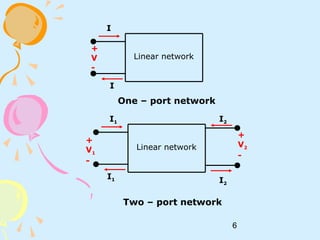
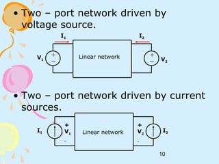
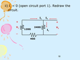
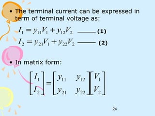
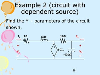
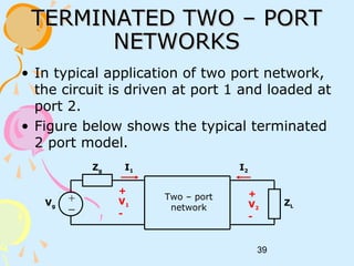
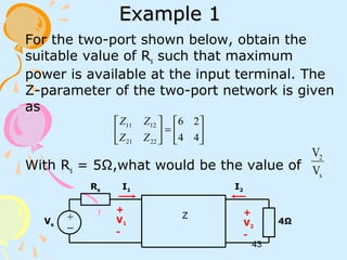
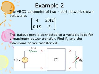
![19
Ω==∴
→
=
=
96Z
(2)(1)sub
)2.......(
400
160
)1.......(240
2
2
22
2
2
I
V
II
IV
x
x
Ω==∴
→
=
=
72
(3)(4)sub
)4.......(
400
240
)3.......(120
2
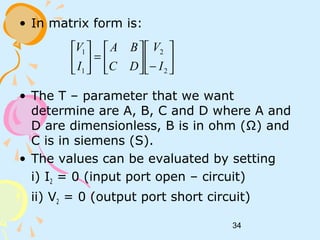
1
12
2
1
I
V
Z
II
IV
y
y
[ ]
=
9672
7284
Z
In matrix form:](https://image.slidesharecdn.com/ec4daf8c-bce8-4f84-a04e-845c4e9a62b8-161003062849/85/2portnetwork-150303092056-conversion-gate01-19-320.jpg)
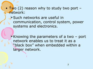
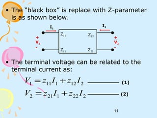
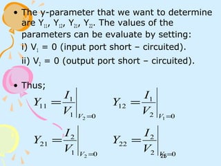
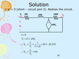
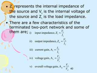
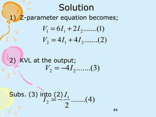
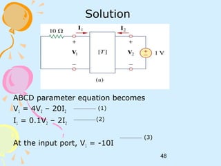
![22
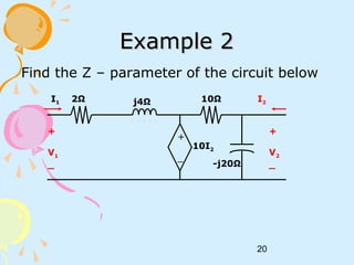
ii) I1 = 0 (open circuit port 1). Redraw the circuit.
Ω==∴
+=
+
−
=
Ω==∴
=
j8)-(16
I
V
Z
10
1
20
j
V2I
10
10I-V
j20
V
I
10
I
V
Z
10IV
2
2
22
22
222
2
2
1
12
21
[ ]
+
=
j8)-(1610
0j4)(2
Z
form;matrixIn
+
_
+
V1
_
+
V2
_-j20Ω
10Ω
10I2
I2I1 = 0](https://image.slidesharecdn.com/ec4daf8c-bce8-4f84-a04e-845c4e9a62b8-161003062849/85/2portnetwork-150303092056-conversion-gate01-22-320.jpg)
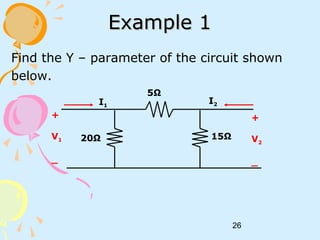
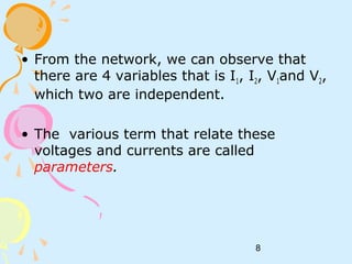
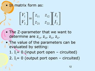
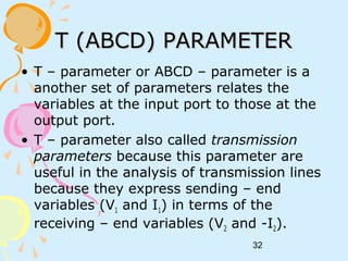
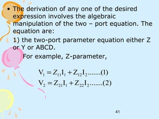
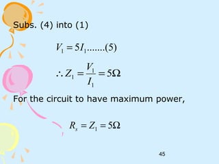
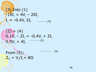
![28
ii) V1 = 0
In matrix form;
5Ω
15Ω
+
V2
_
I1
I2
Ix
S
V
I
Y
II
IV
x
x
15
4
(4)(3)sub
)4.......(
25
5
)3.......(15
2
2
22
2
2
==∴
→
=
=
S
V
I
Y
IV
5
1
5
2
1
12
12
−==∴
−=
[ ] SY
−
−
=
15
4
5
1
5
1
4
1](https://image.slidesharecdn.com/ec4daf8c-bce8-4f84-a04e-845c4e9a62b8-161003062849/85/2portnetwork-150303092056-conversion-gate01-28-320.jpg)
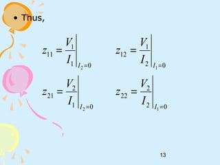
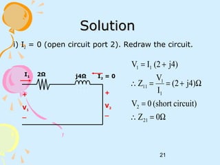
![31
ii) V1 = 0 (short – circuit port 1). Redraw the circuit.
)2.......(
j20-
1
10
1
V2I
10
10I-V
j20-
V
I
)........(1
j42
10I-
I
22
222
2
2
1
+=
+=
+
=
+
_
+
V2
_-j20Ω
10Ωj4Ω2Ω
10I2
I2I1
[ ] S
j0.0250.050
j0.0751.0j0.20.1
Y
form;matrixIn
Sj0.075)(-0.1
V
I
Y
(1)(2)sub
Sj0.025)(0.05
V
I
Y
2
1
12
2
2
22
+
+−+
=∴
+==
→
+==∴](https://image.slidesharecdn.com/ec4daf8c-bce8-4f84-a04e-845c4e9a62b8-161003062849/85/2portnetwork-150303092056-conversion-gate01-31-320.jpg)
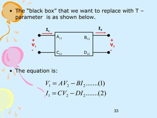
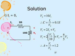
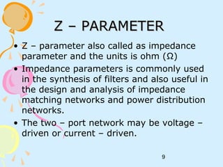
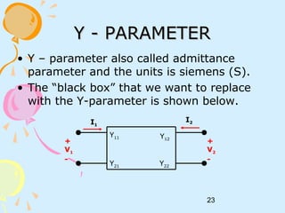
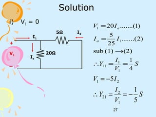
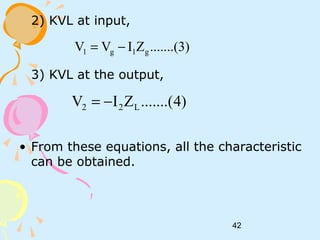
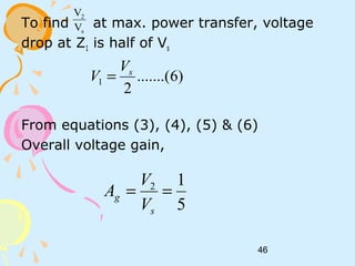
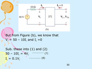
![38
ii) V2 = 0,
( )
Ω=−=∴
+
−=
+=
++=
=−=∴
−=
8.6
10
10
14
12
1012
102
4.1
14
10
2
1
221
211
2111
2
1
12
I
V
B
IIV
IIV
IIIV
I
I
D
II
2Ω
10Ω
I1 I2
+
V1
_
4Ω
I1 + I2
[ ]
=
4.11.0
8.62.1
T](https://image.slidesharecdn.com/ec4daf8c-bce8-4f84-a04e-845c4e9a62b8-161003062849/85/2portnetwork-150303092056-conversion-gate01-38-320.jpg)

This document discusses two-port networks and their parameters. It defines a two-port network as having two ports for input and output, with four variables - I1, I2, V1, V2. The parameters that relate these variables are Z (impedance), Y (admittance), and T (ABCD transmission). It provides examples of calculating the parameters for given circuits by opening or closing ports. The objectives are to understand two-port networks and analyze their behavior using different parameter representations.


![Experimentdsd[1]](https://cdn.slidesharecdn.com/ss_thumbnails/experimentdsd1-121006103055-phpapp01-thumbnail.jpg?width=640&height=640&fit=bounds)