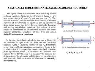
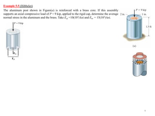
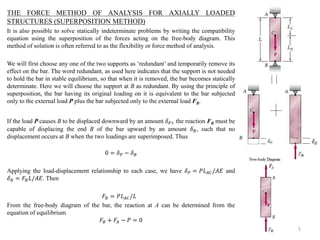
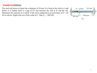
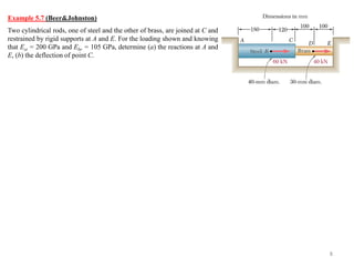
- The document discusses statically determinate and indeterminate axial loaded structures. Statically determinate structures can have their member forces determined from equilibrium equations alone, while indeterminate structures require considering member deformation properties as well.
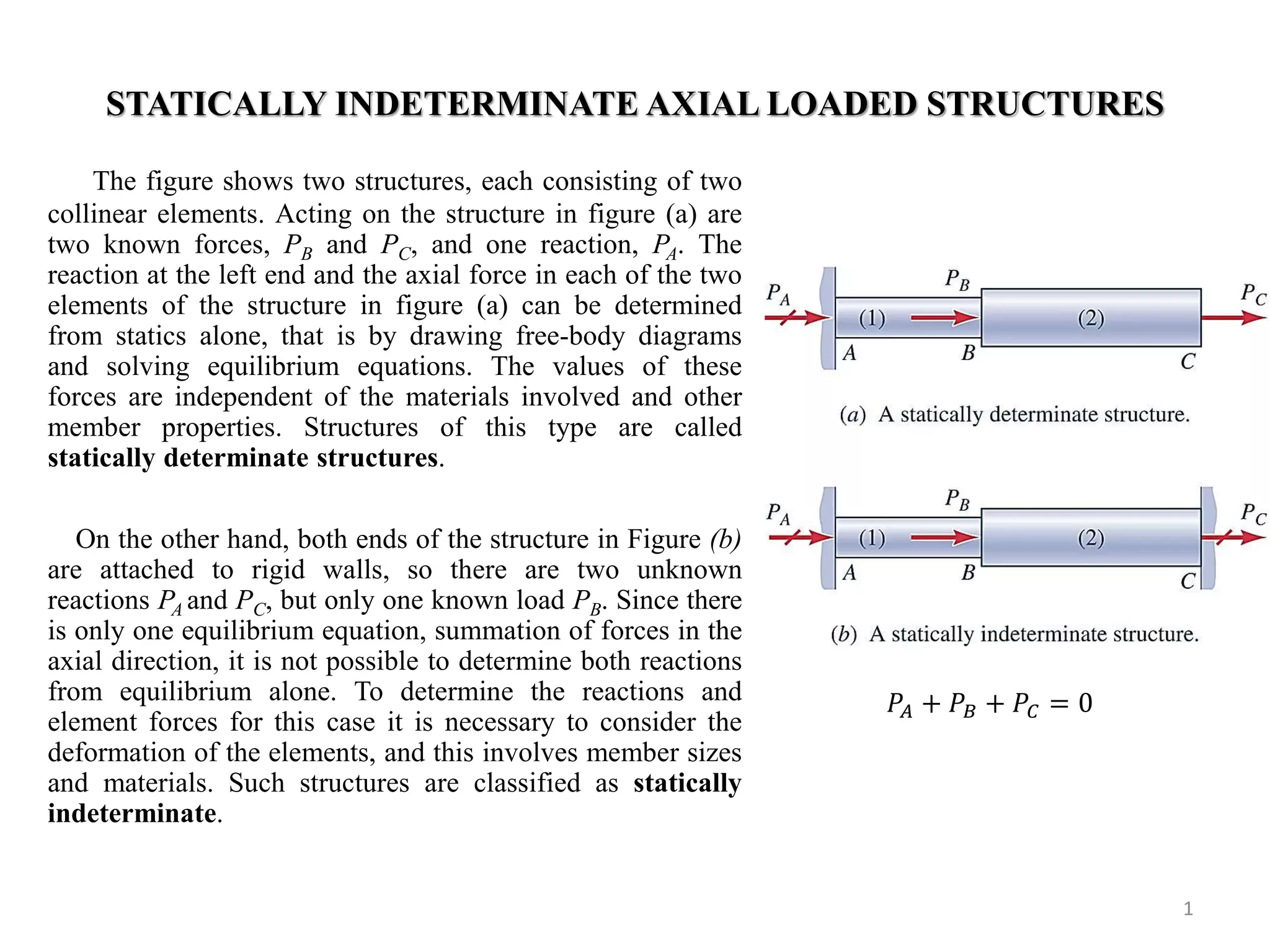
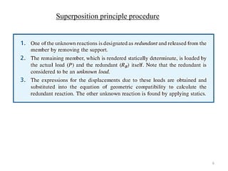
- For indeterminate structures, compatibility equations relating displacement must be written and combined with load-displacement relationships involving member material properties to determine member forces. The force method of analysis using superposition is also described.
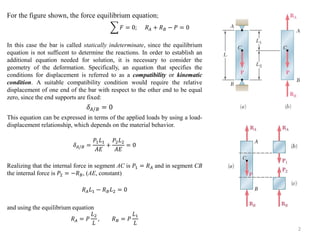
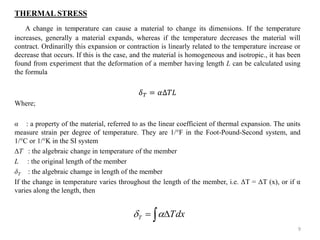
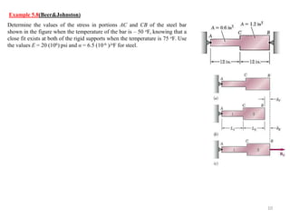
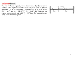
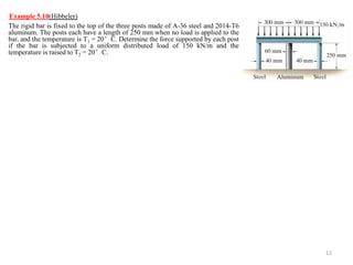
- Thermal stresses in axial members due to temperature changes are discussed, and examples are provided to demonstrate calculating member forces and displacements in loaded structures subjected to temperature changes.