Downloaded 307 times
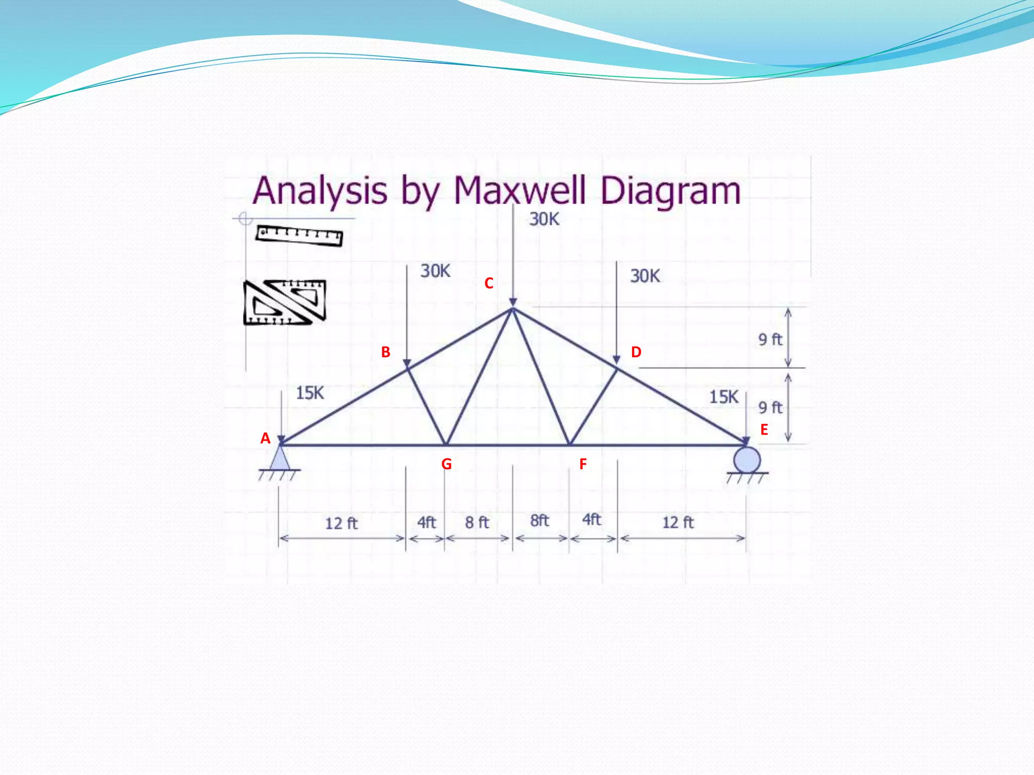
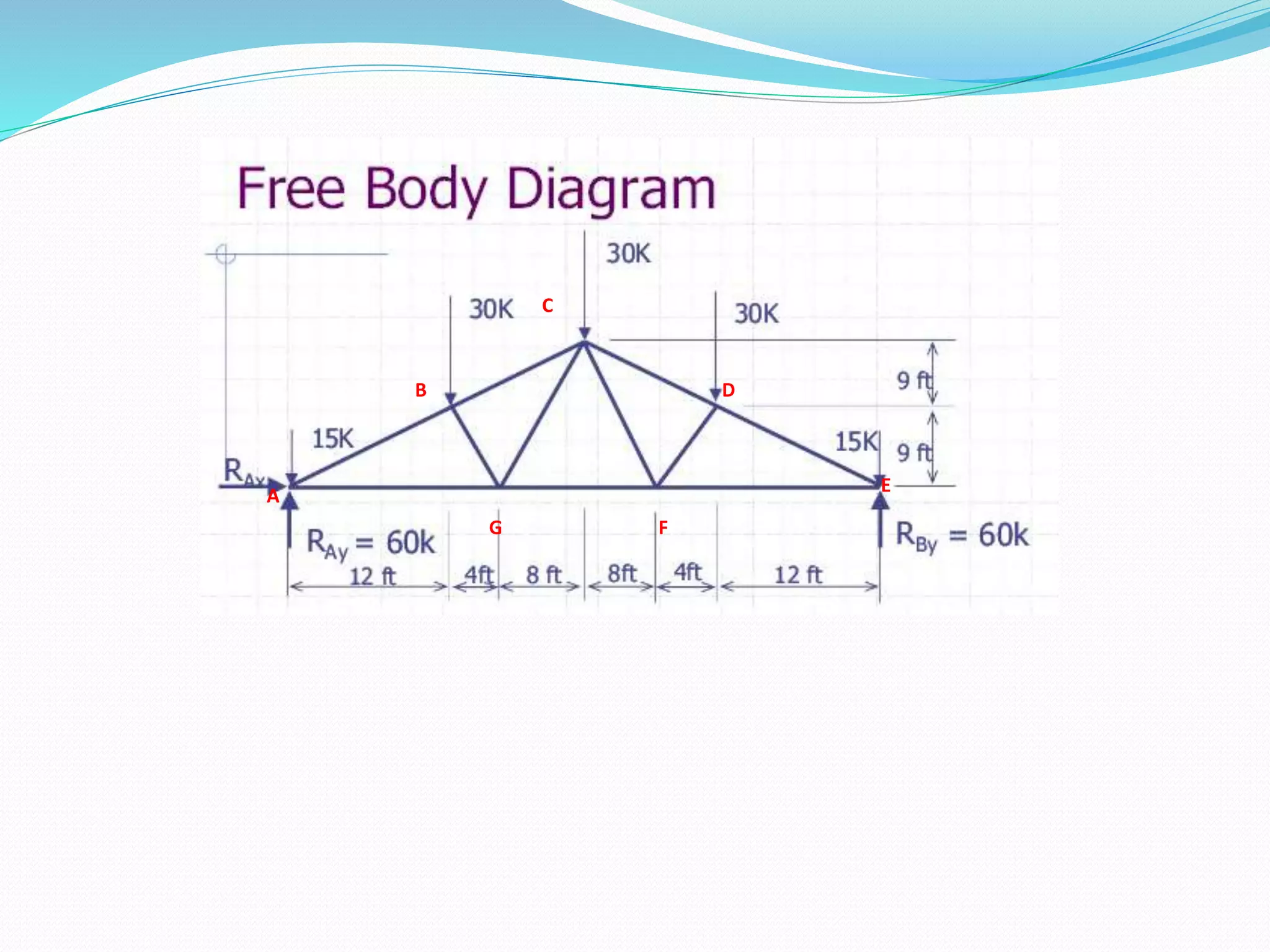
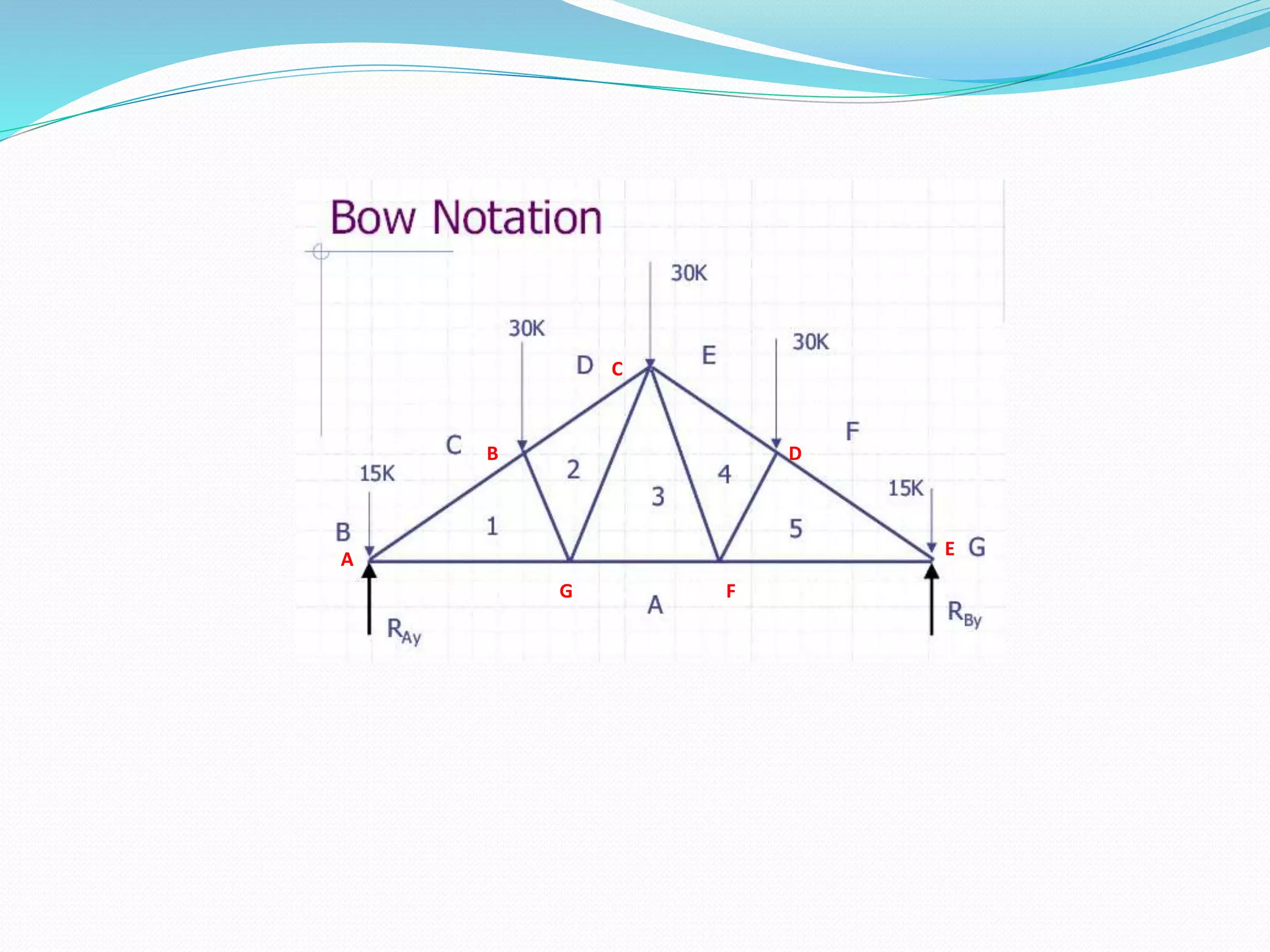
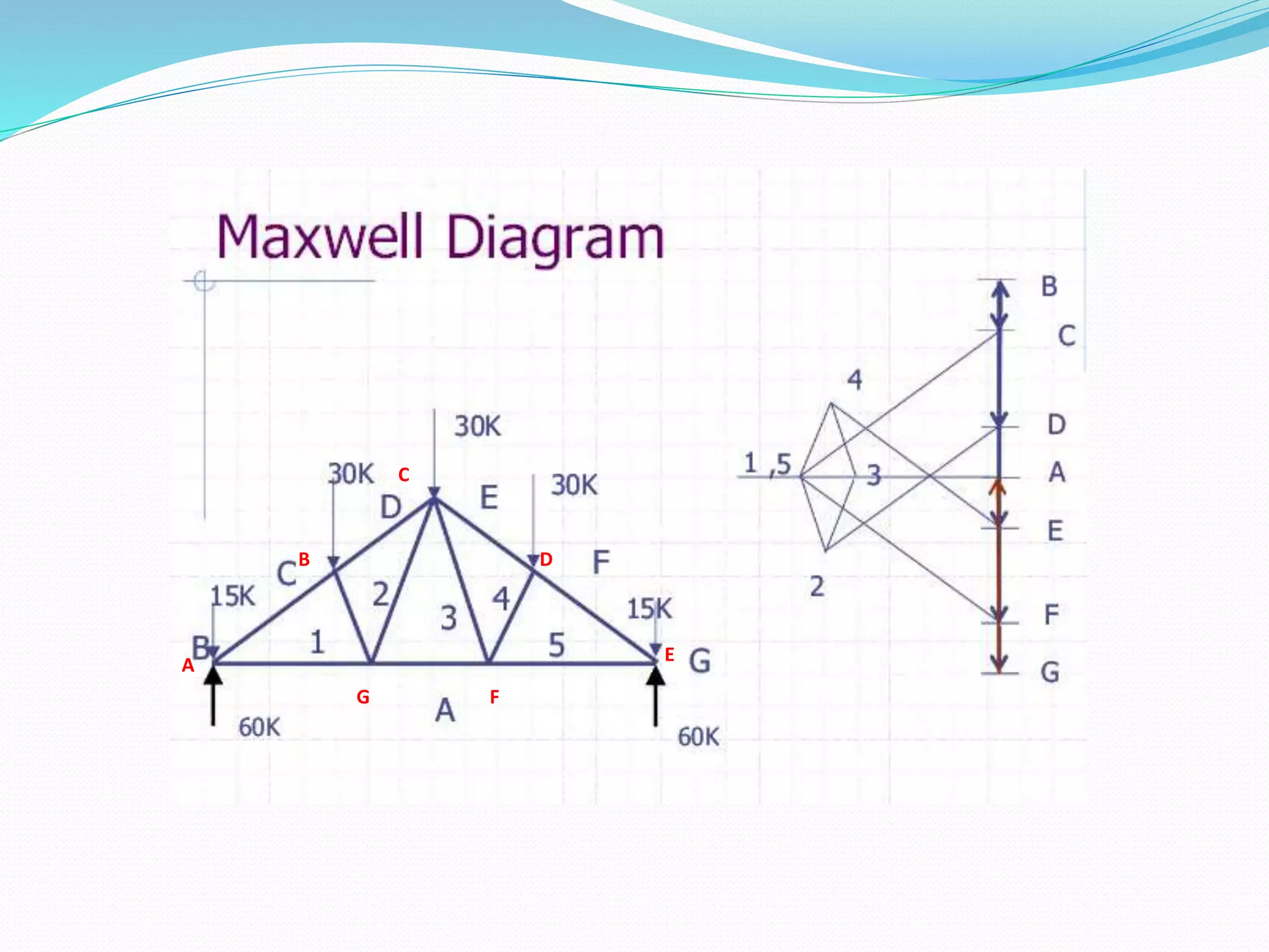

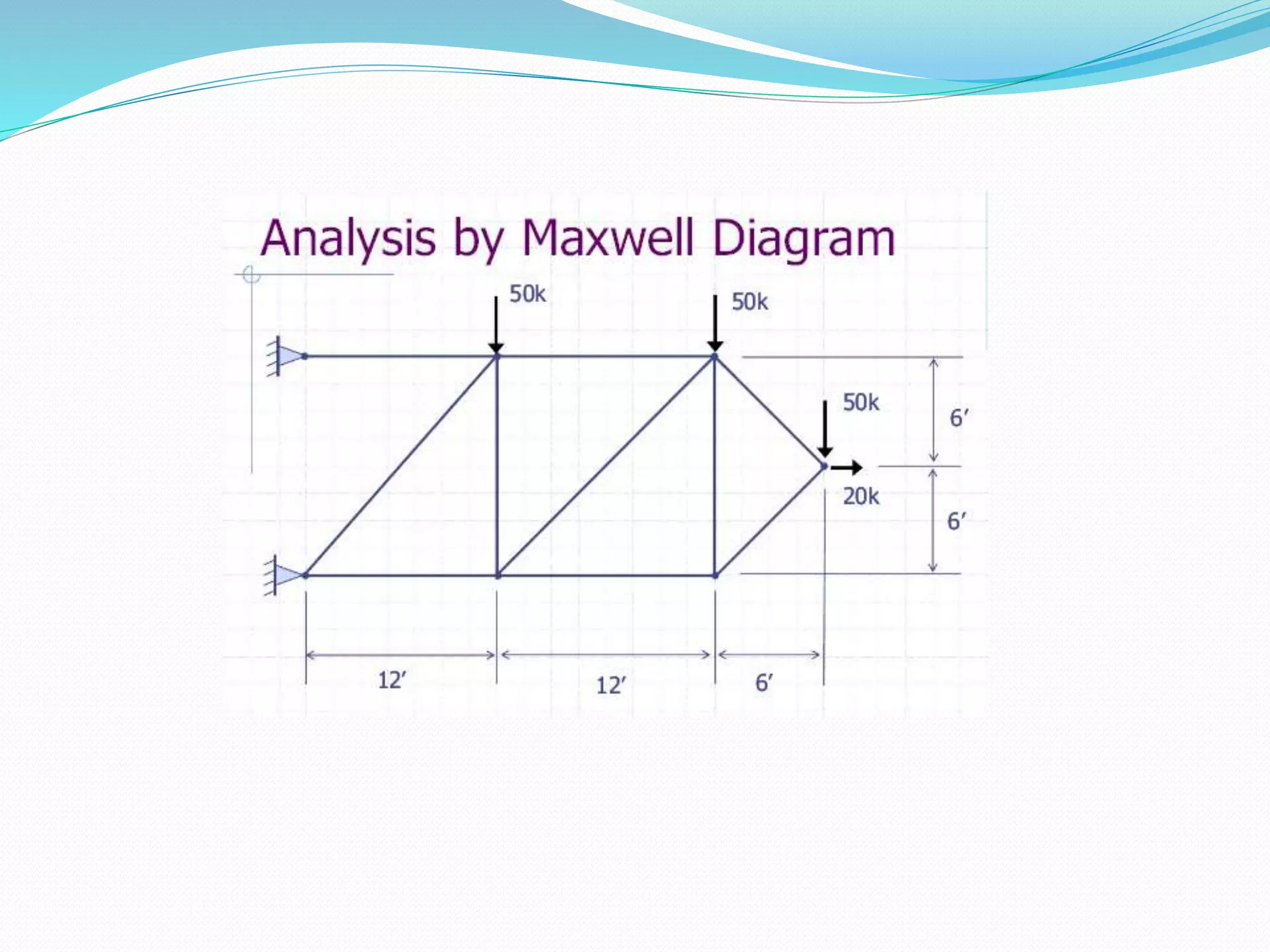
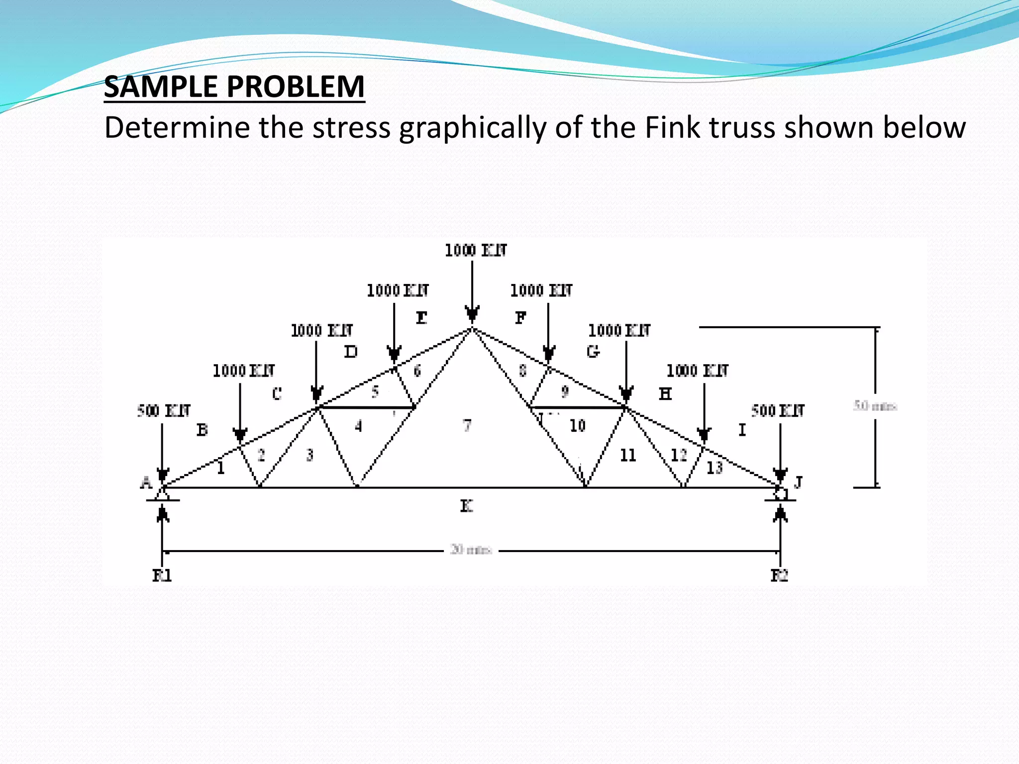
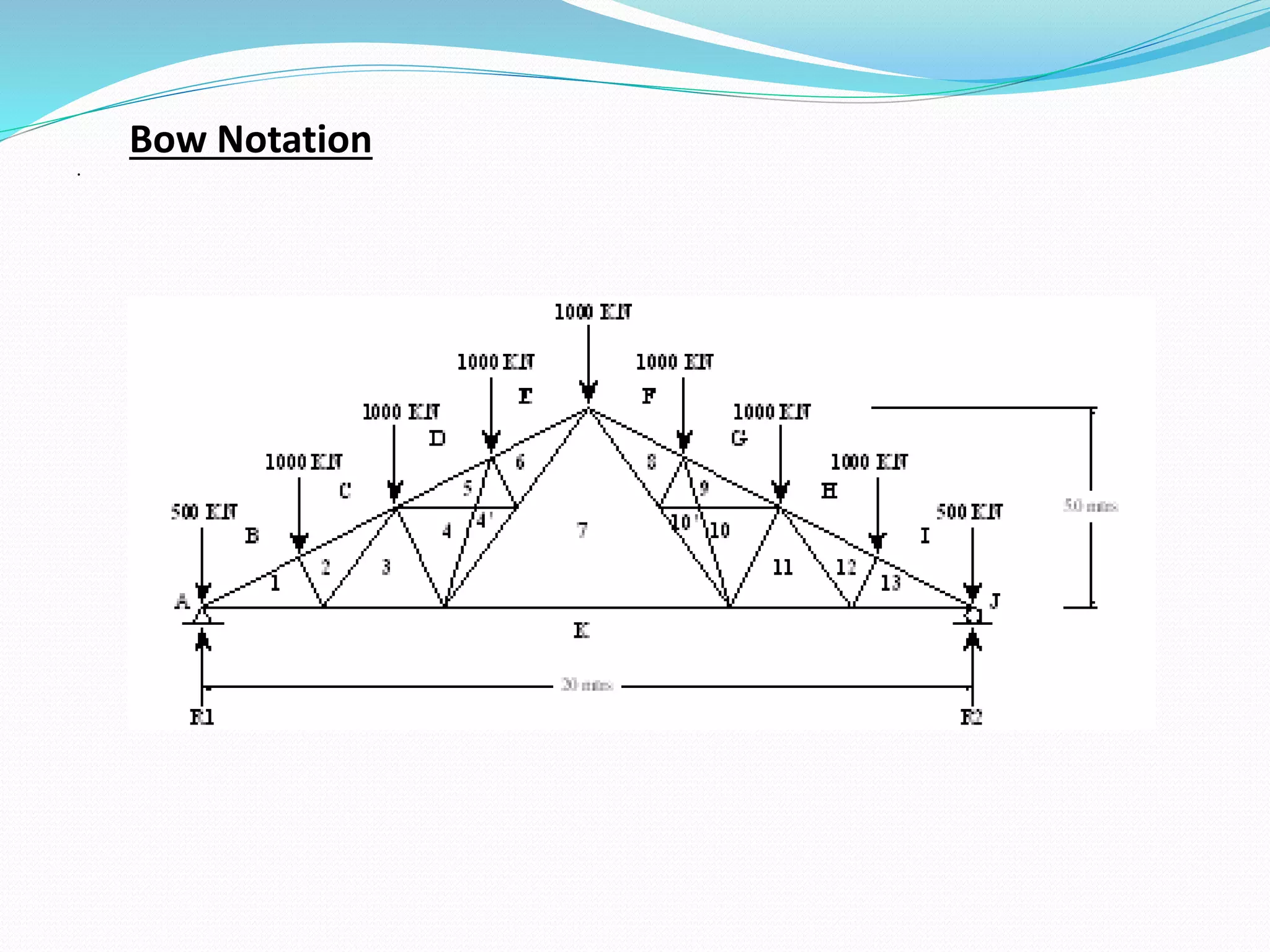
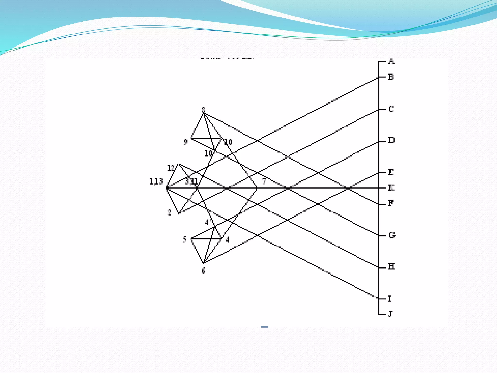
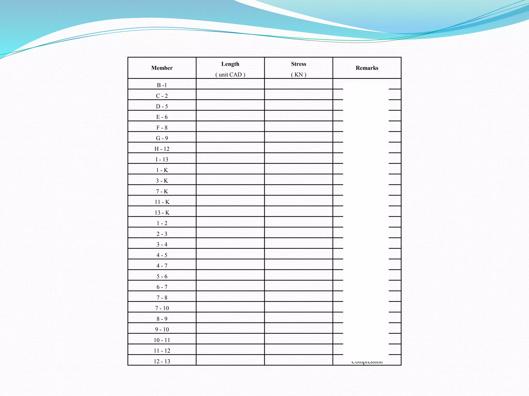

The document describes Maxwell's diagram, a graphical method for analyzing trusses. It involves drawing force polygons to scale for each joint to determine member forces. The process includes solving for support reactions, drawing a force polygon around the entire truss clockwise, then drawing individual force polygons for each joint with two unknown forces to measure member forces from the diagram. As an example, it provides a sample problem to determine stresses in a Fink truss using this graphical method.


