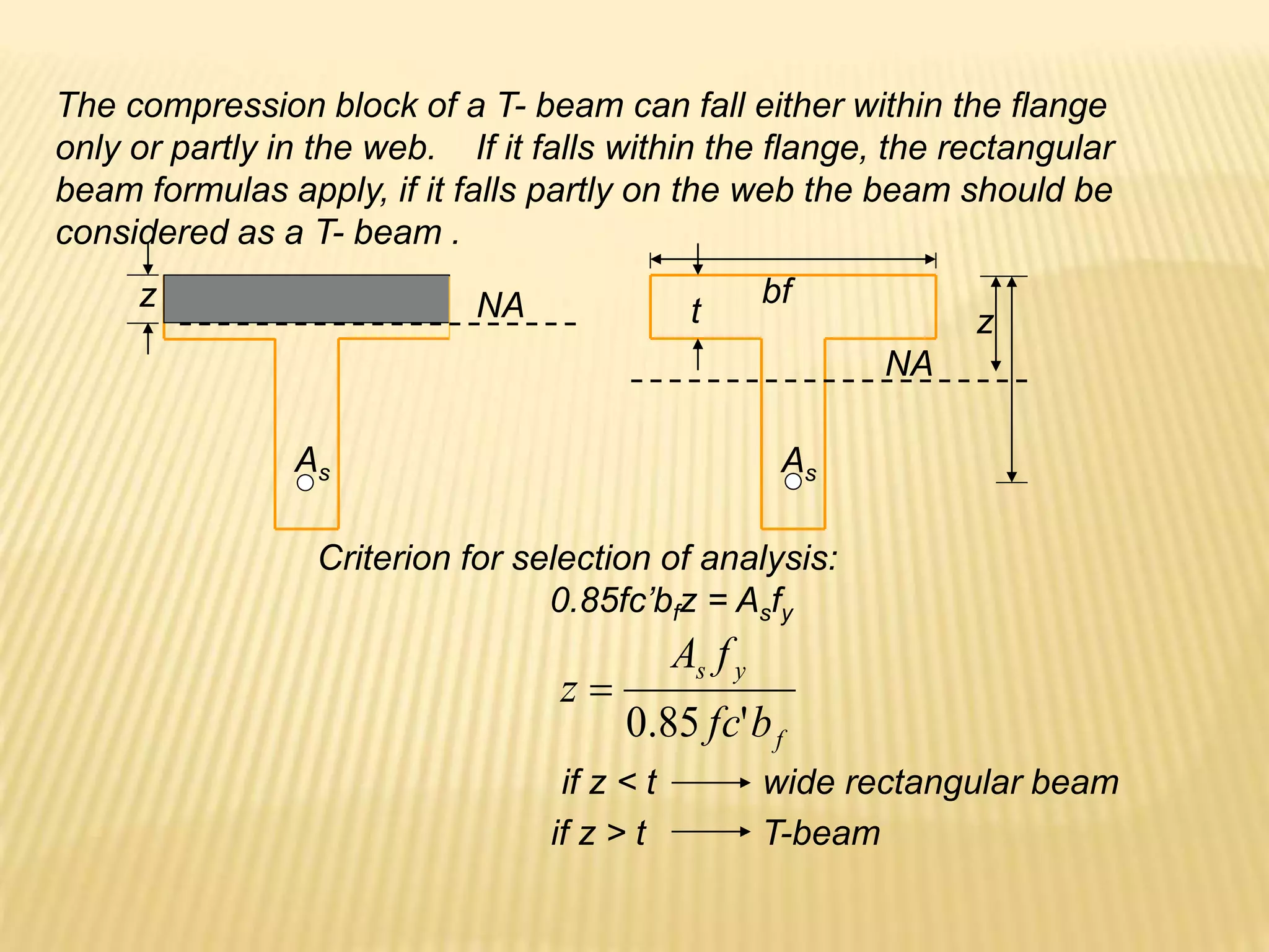
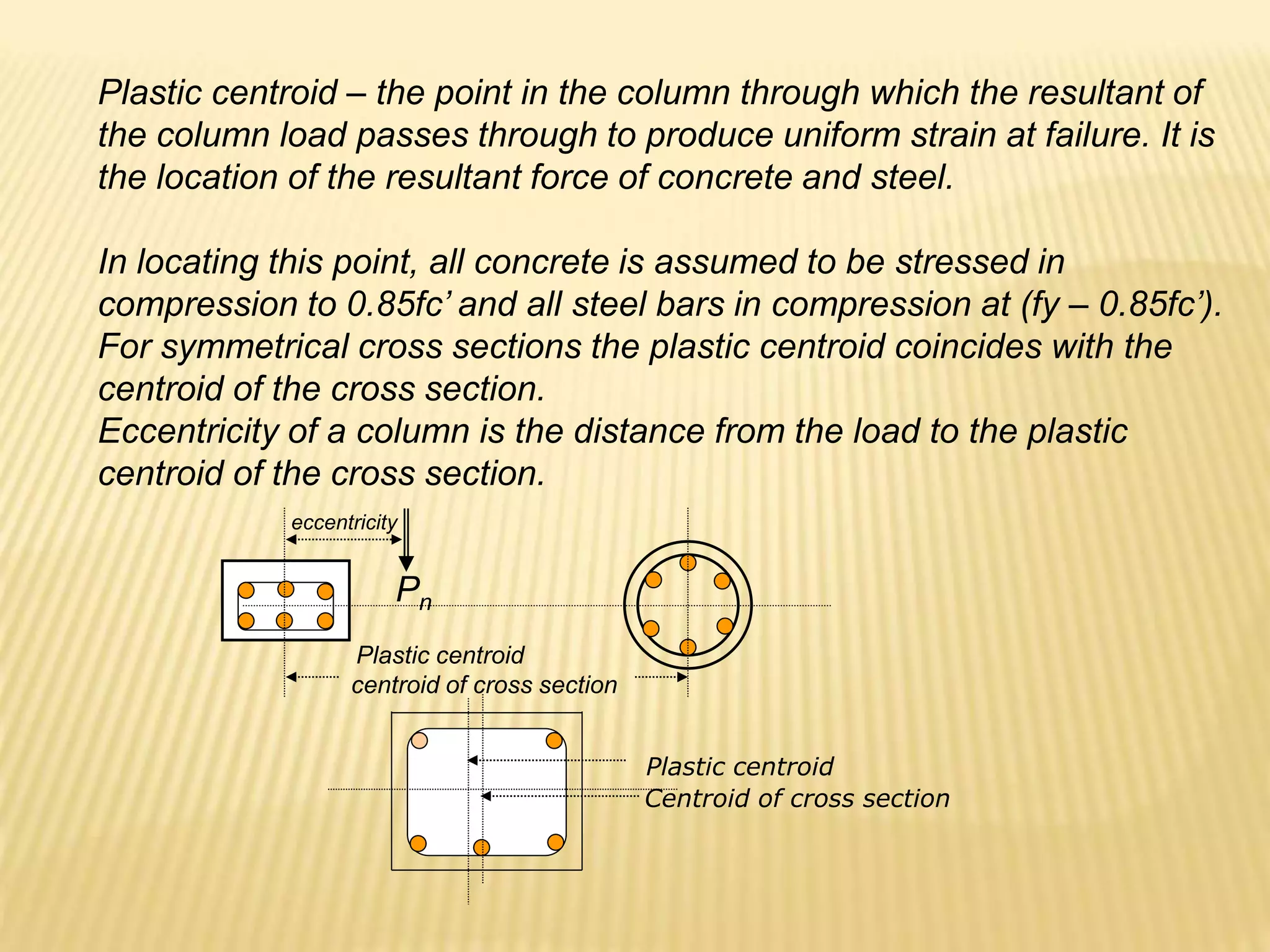
This document provides information on reinforced concrete design including:
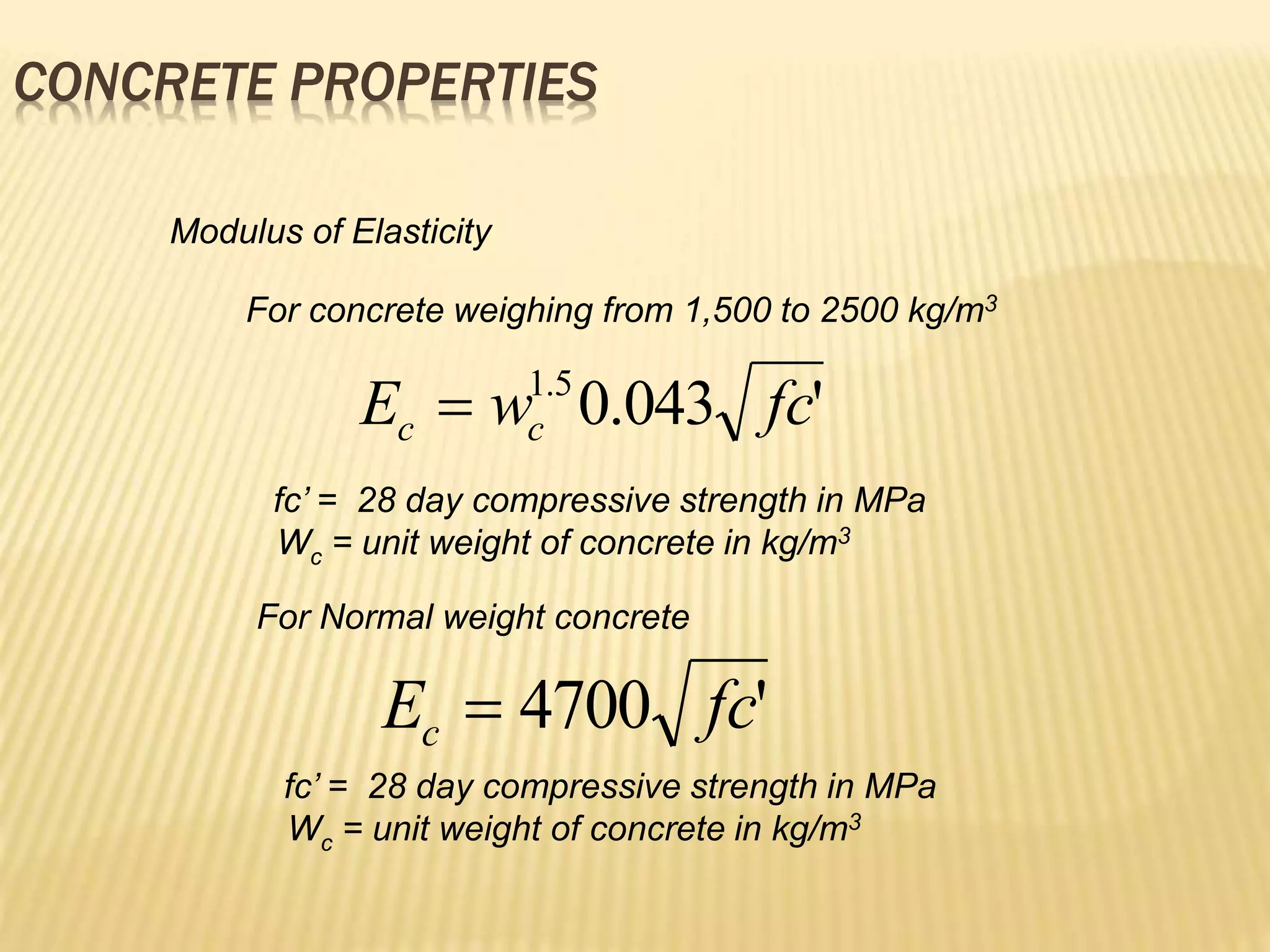
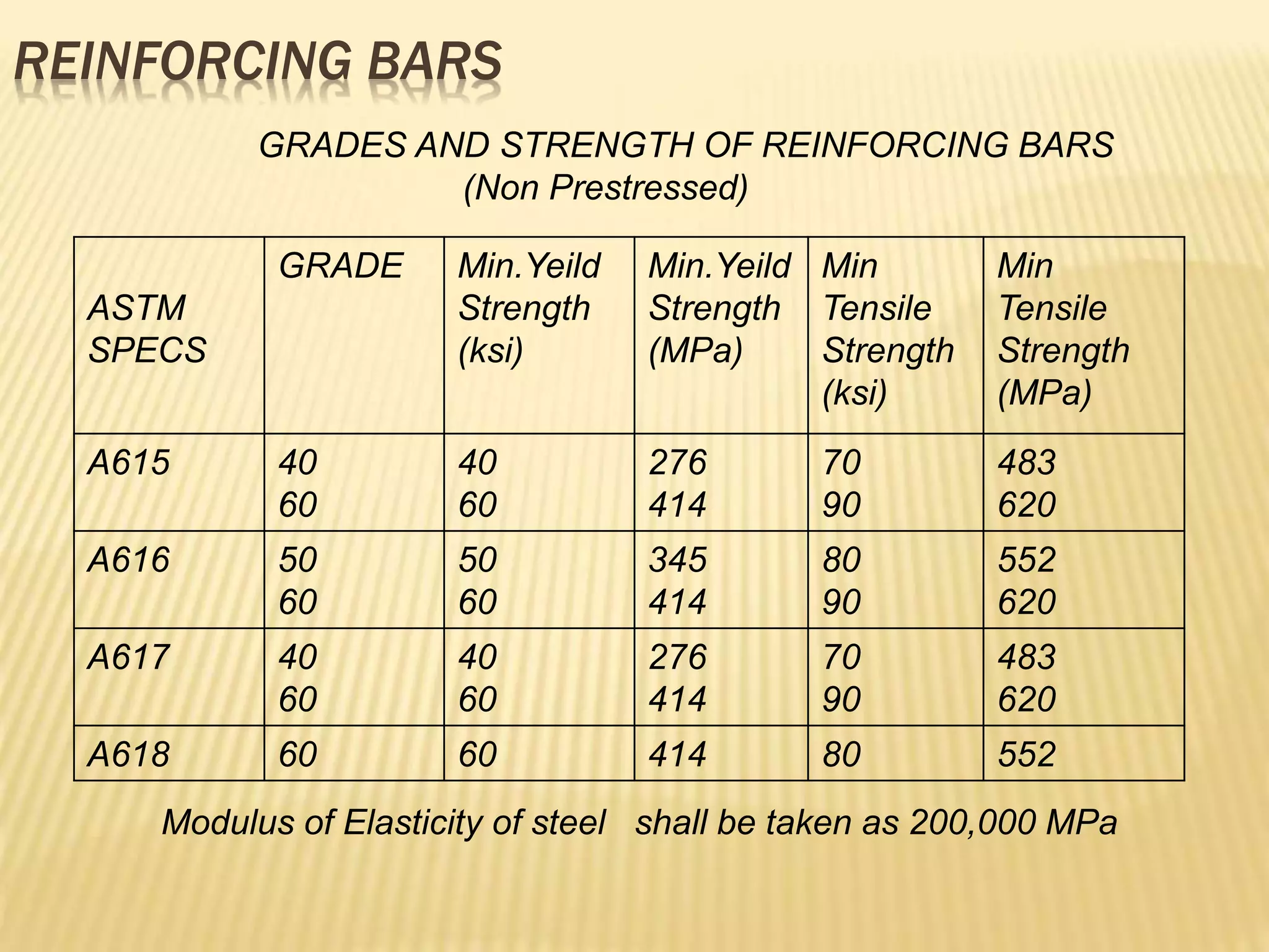
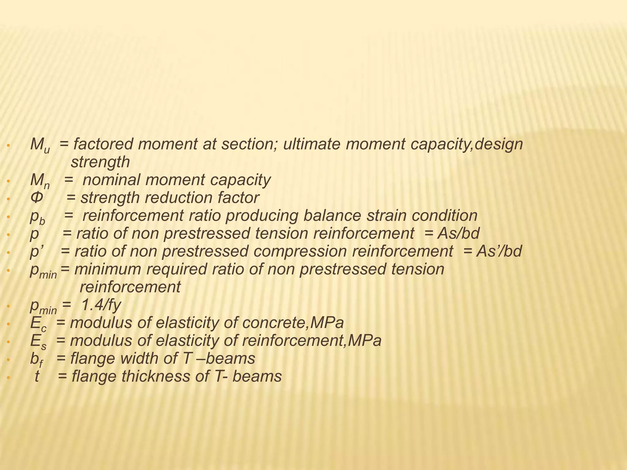
- Concrete and steel properties such as modulus of elasticity and grades/strengths of reinforcing bars.
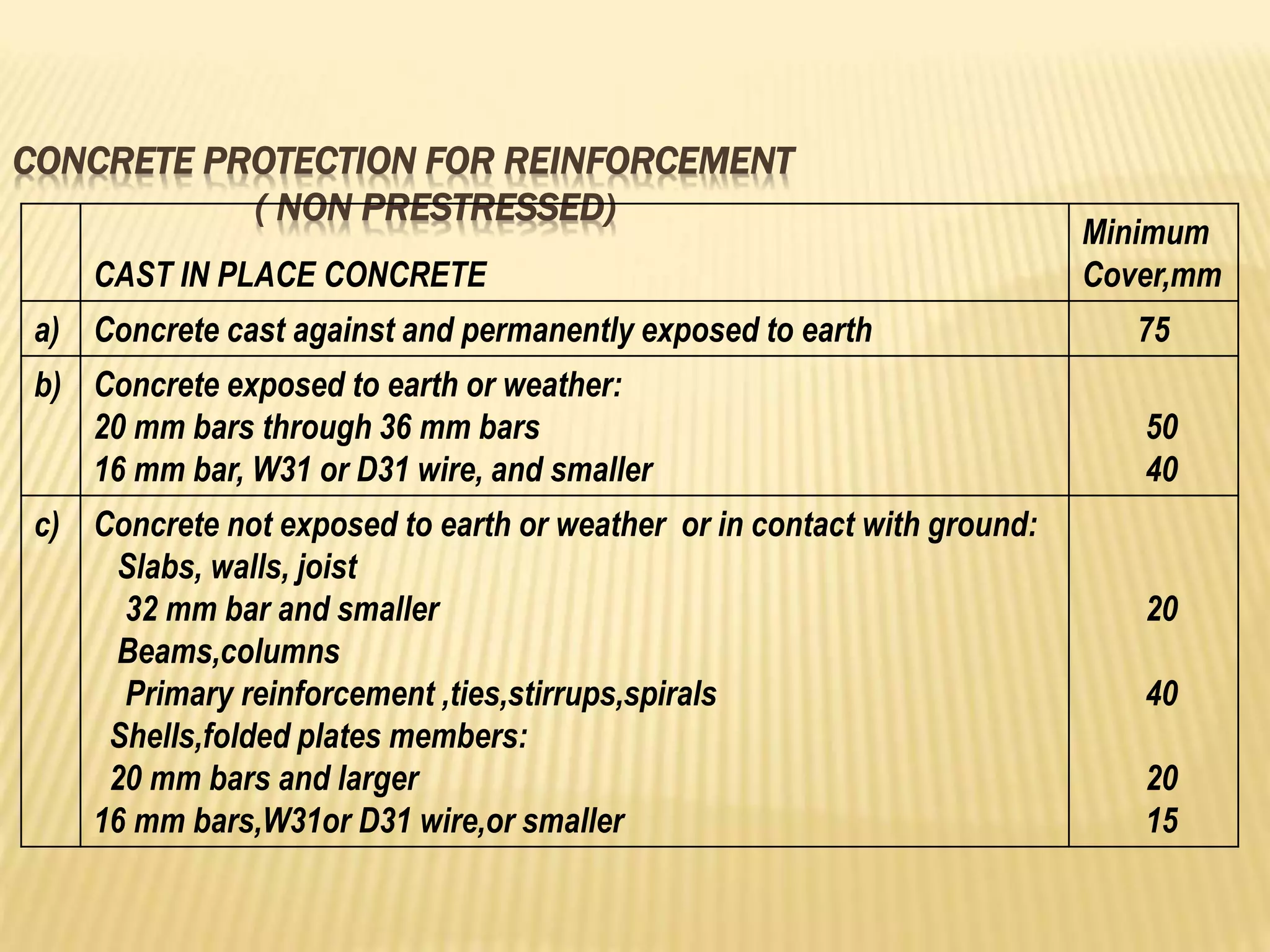
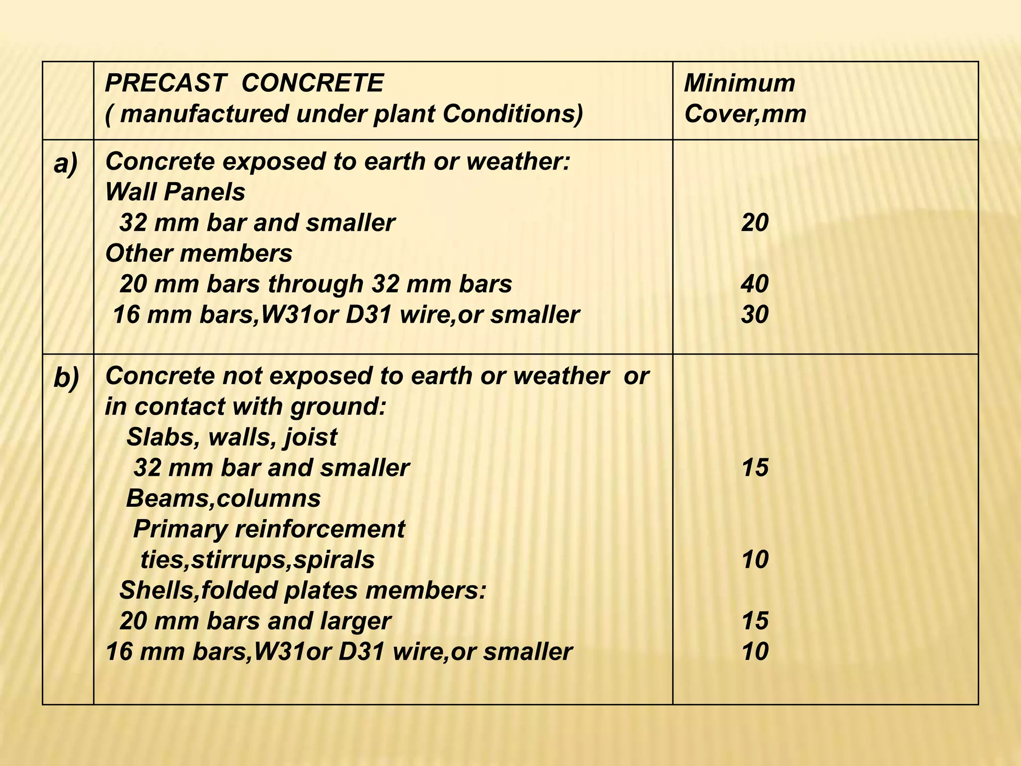
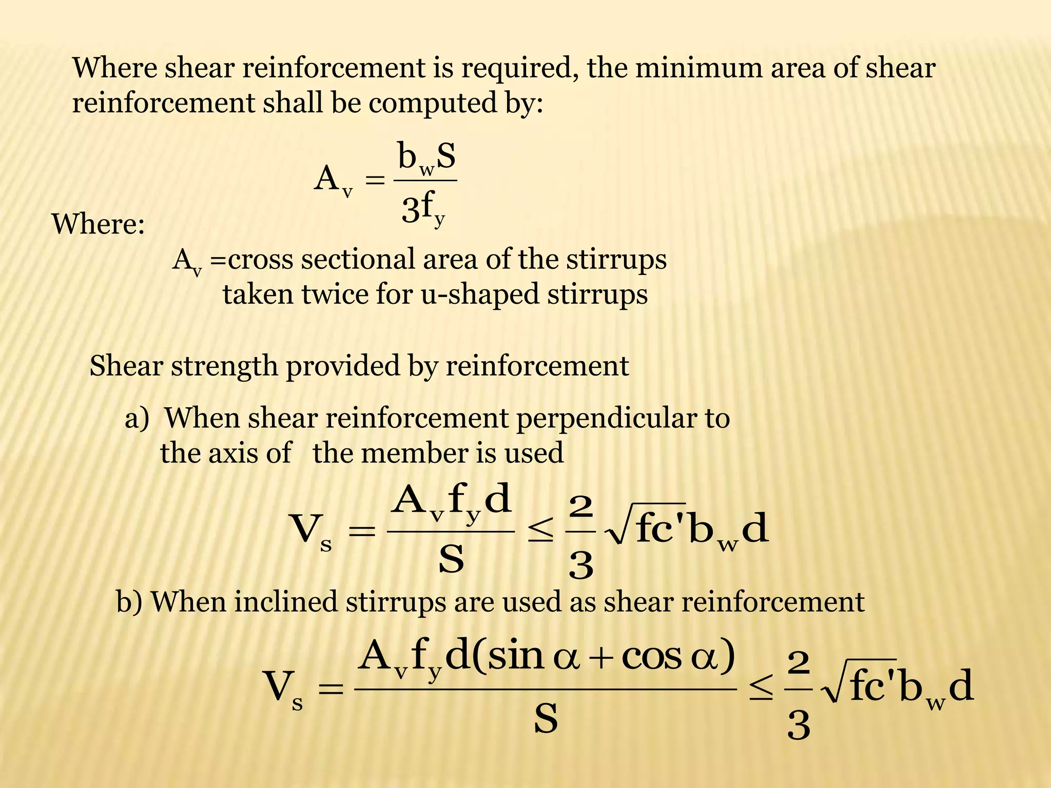
- Minimum concrete cover requirements for reinforcement.
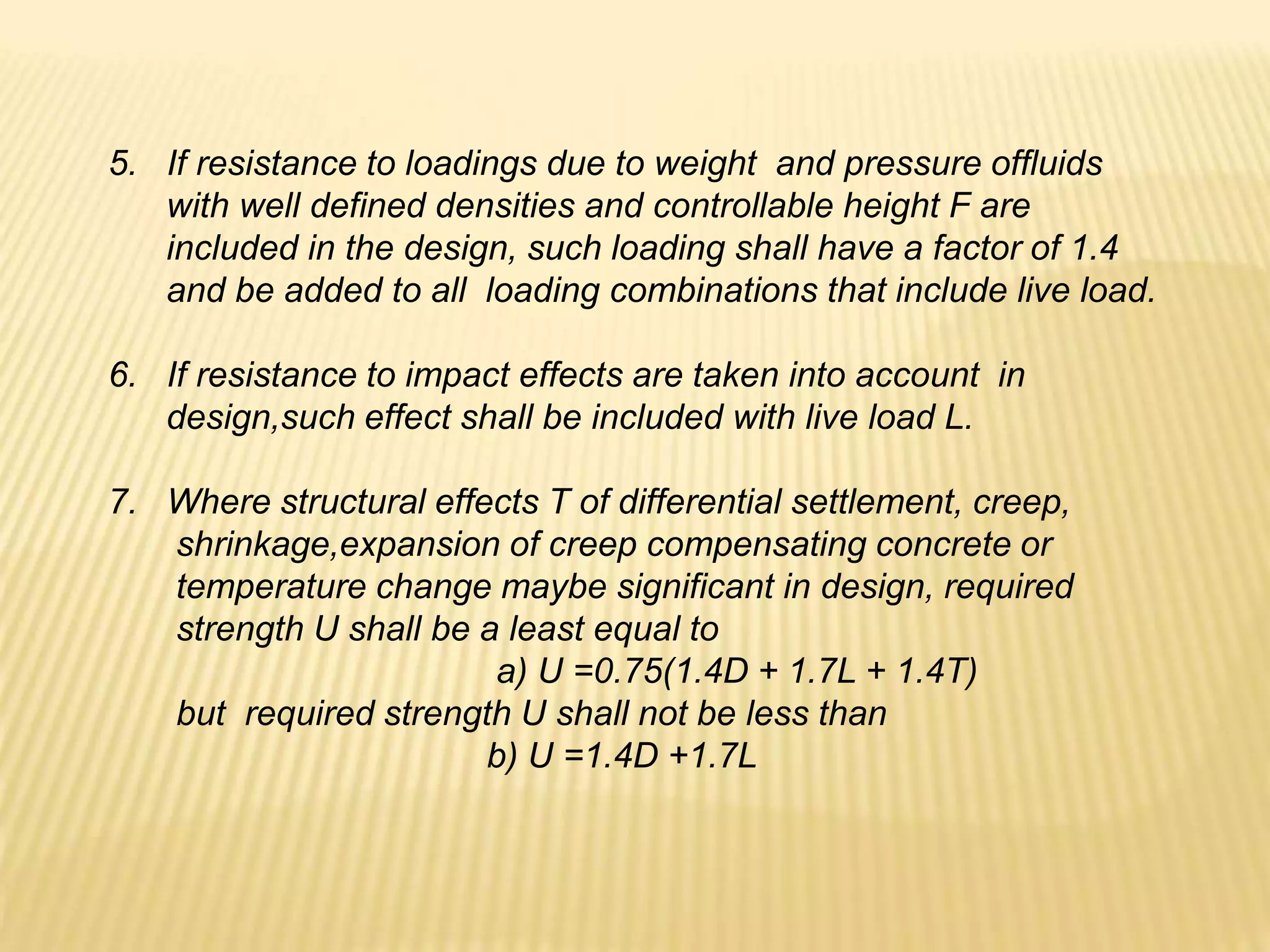
- Load factors and combinations for ultimate strength design.
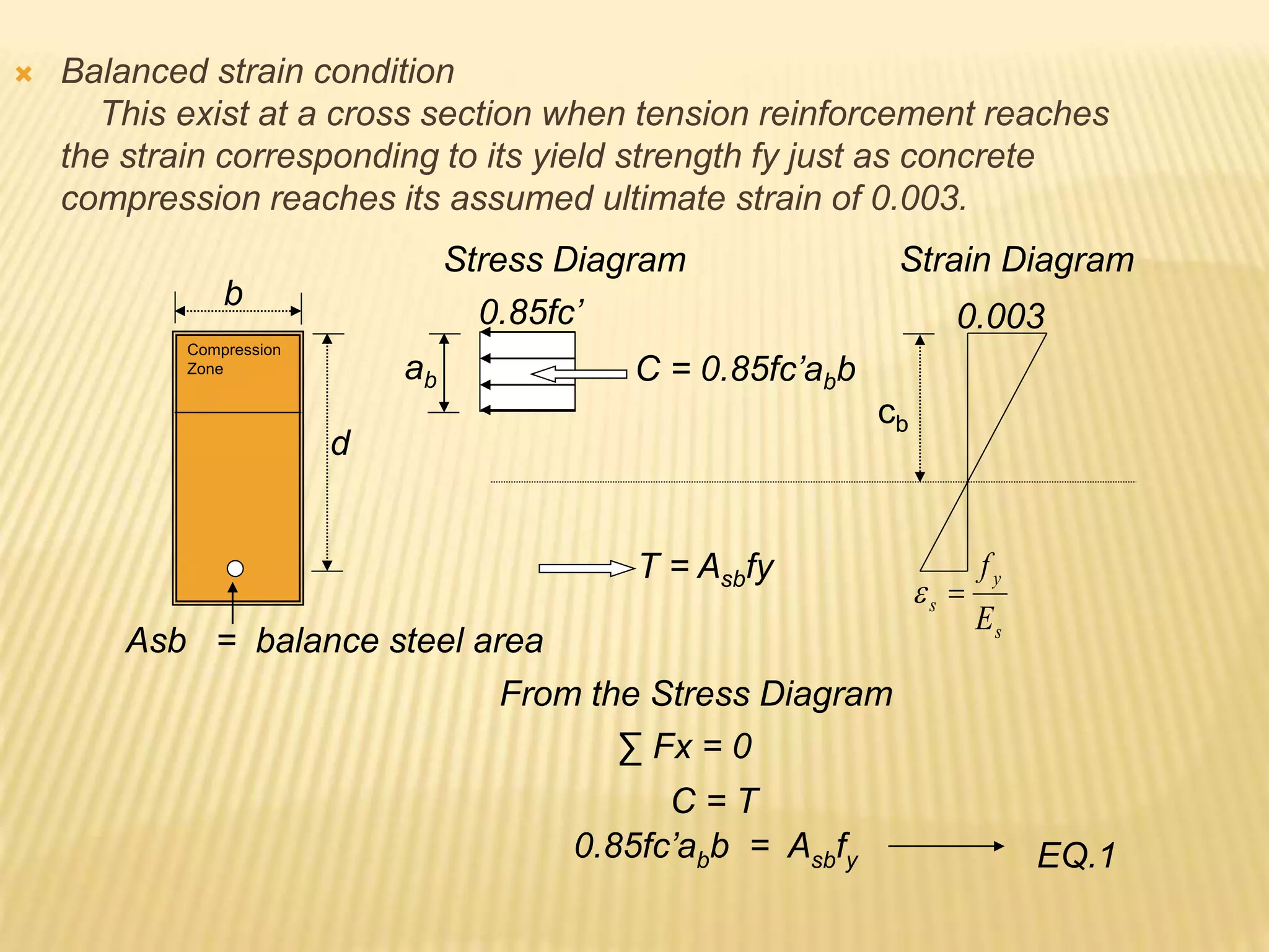
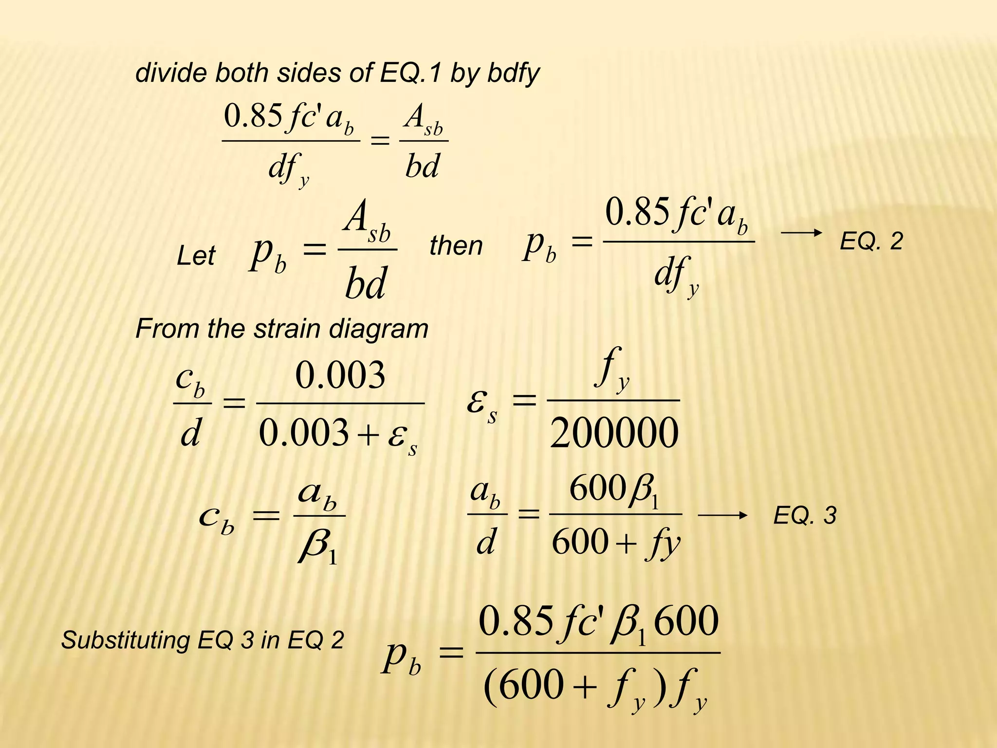
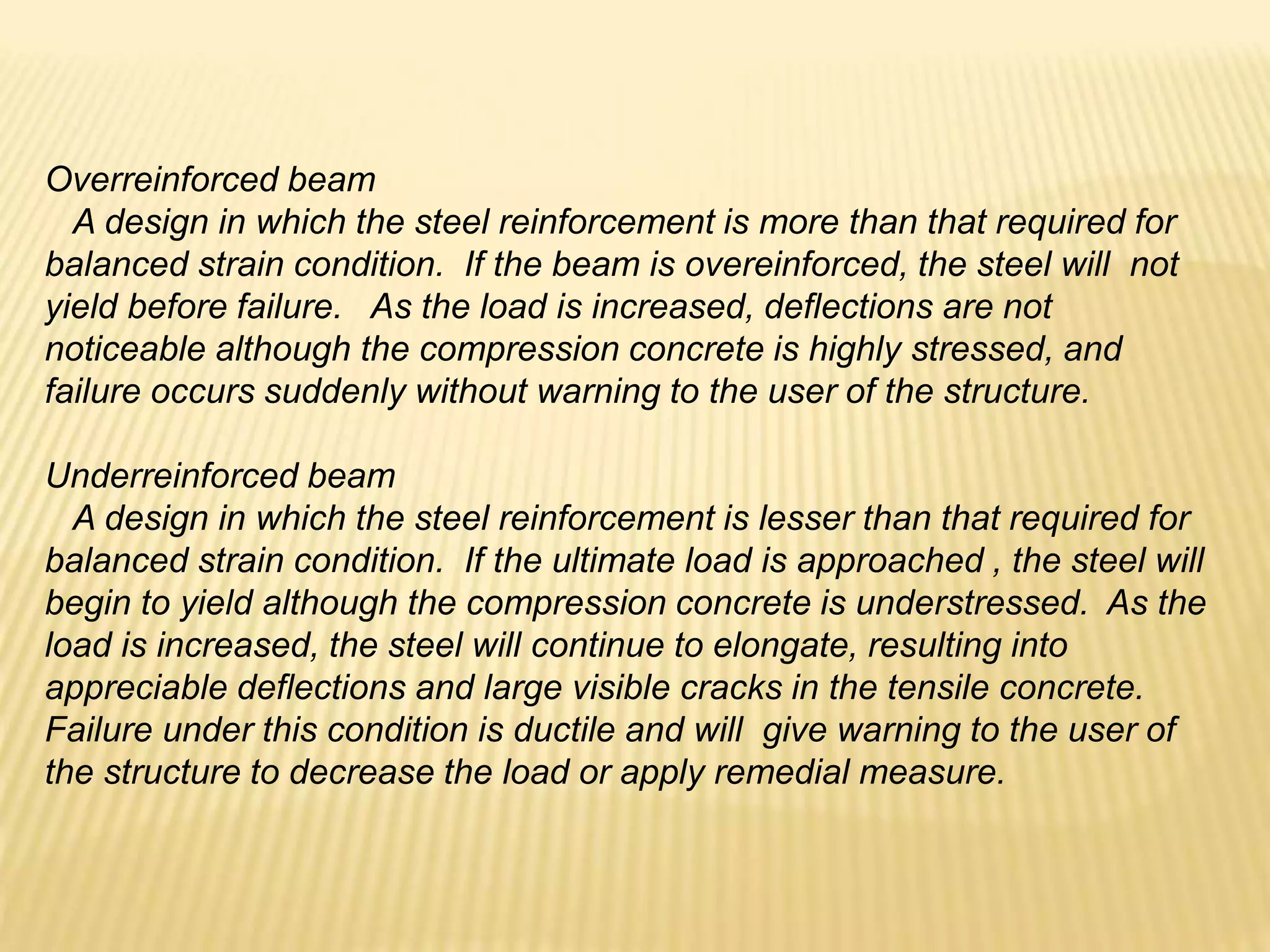
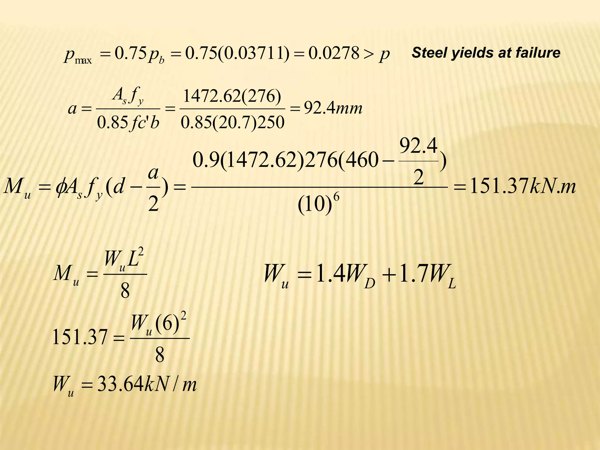
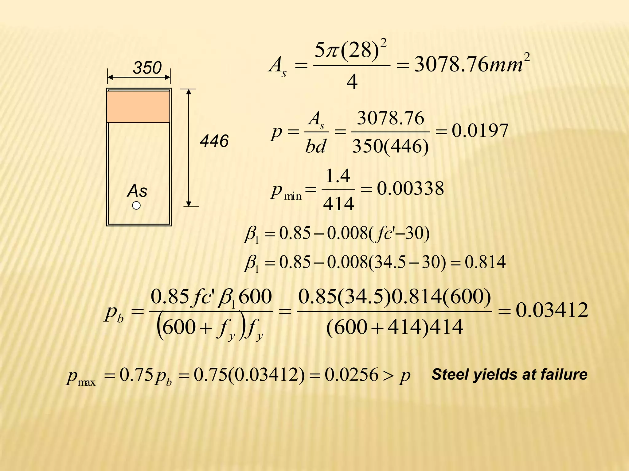
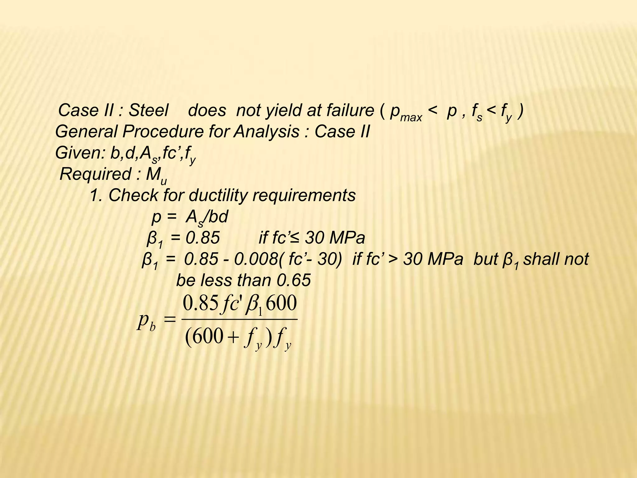
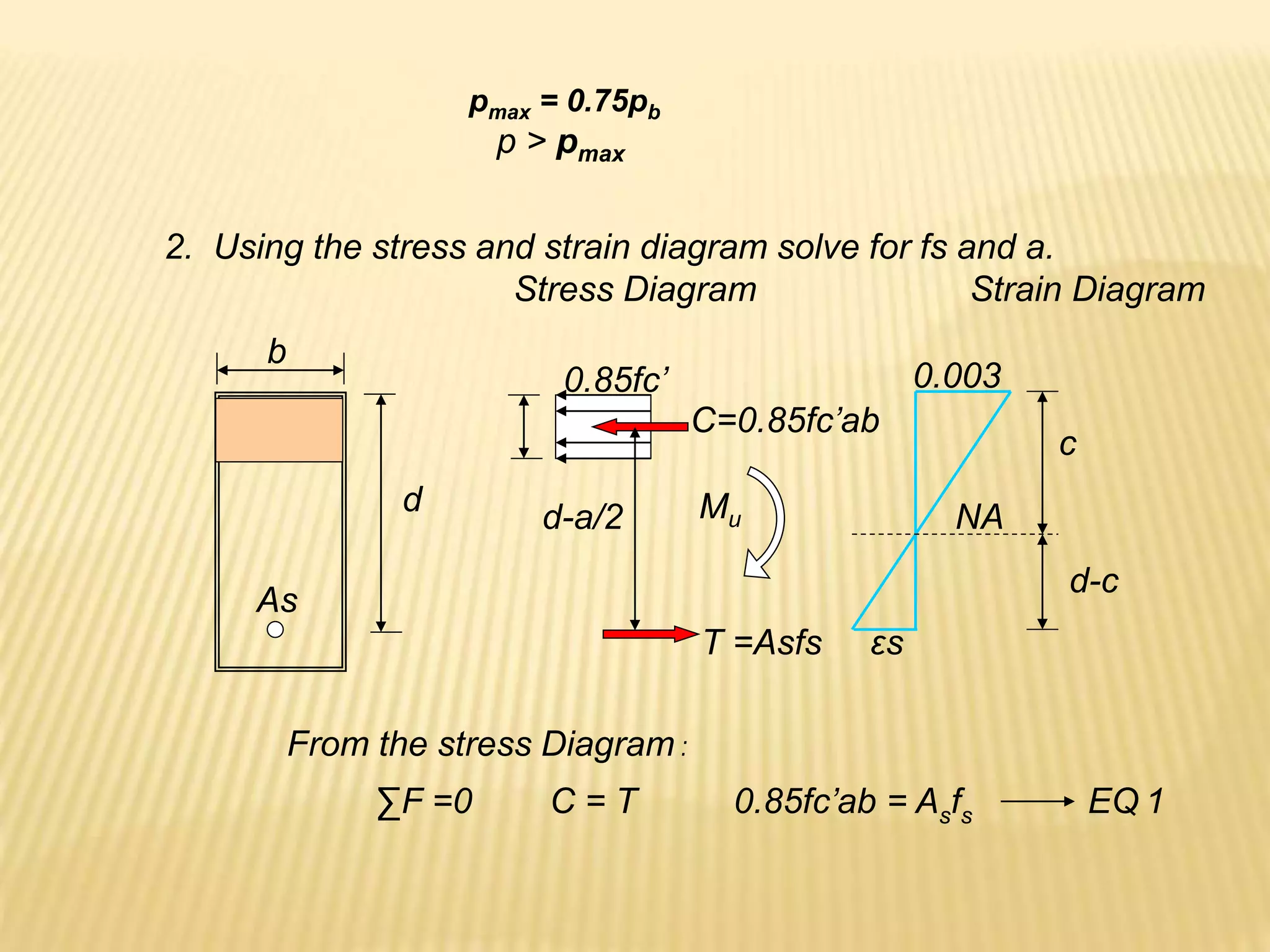
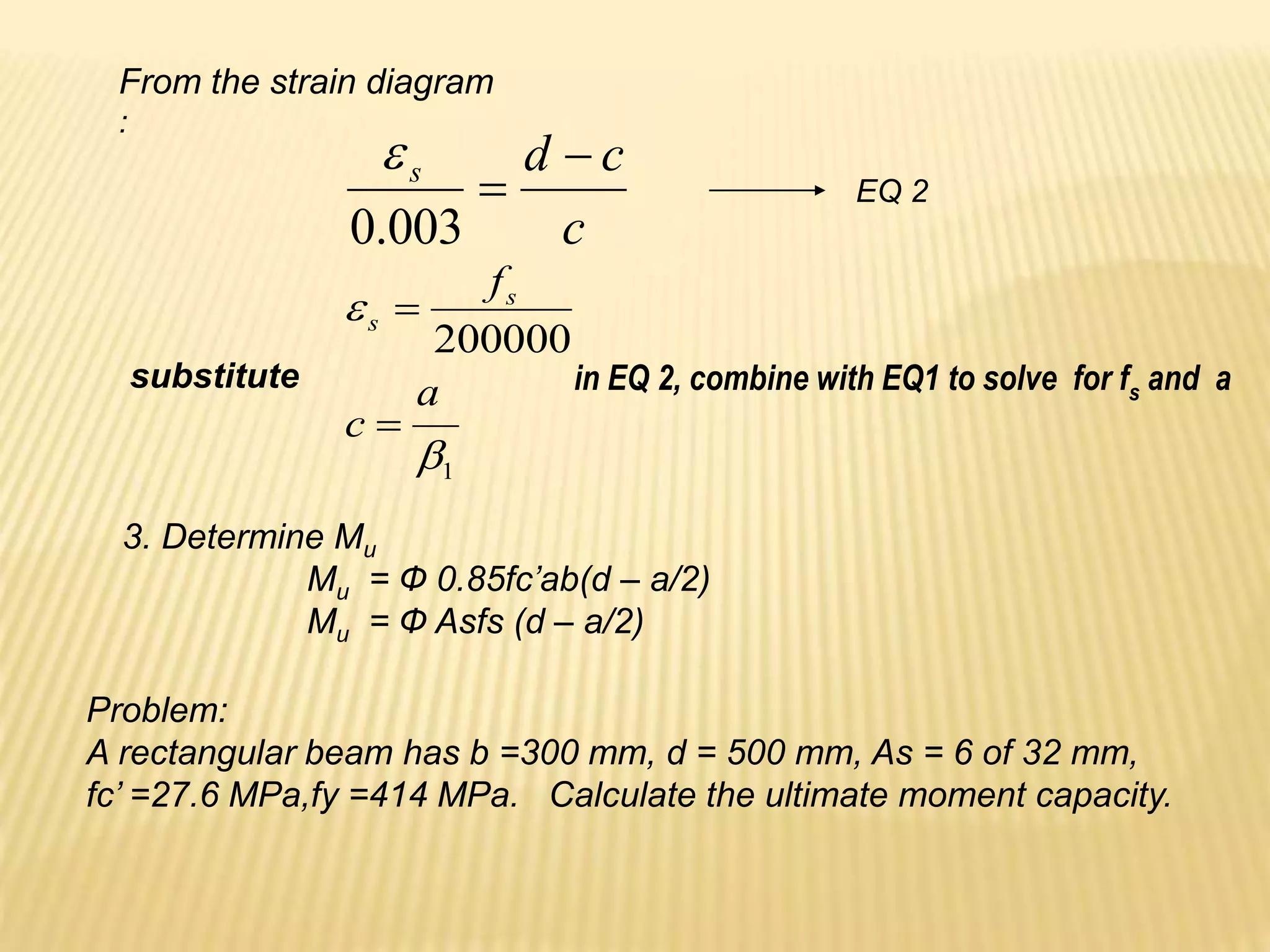
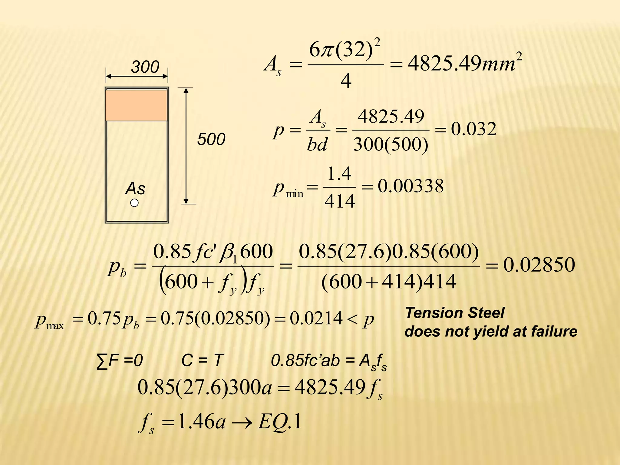
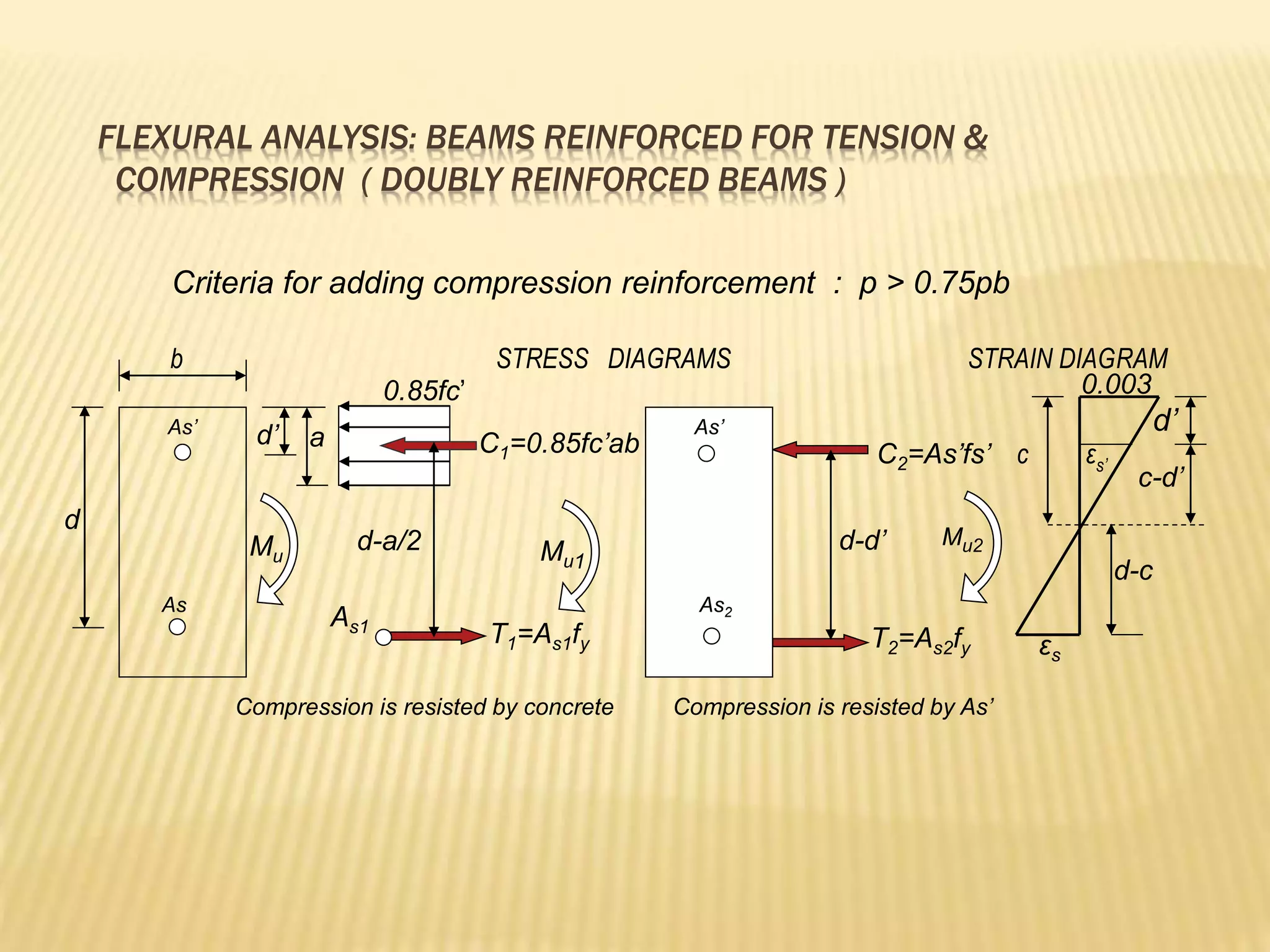
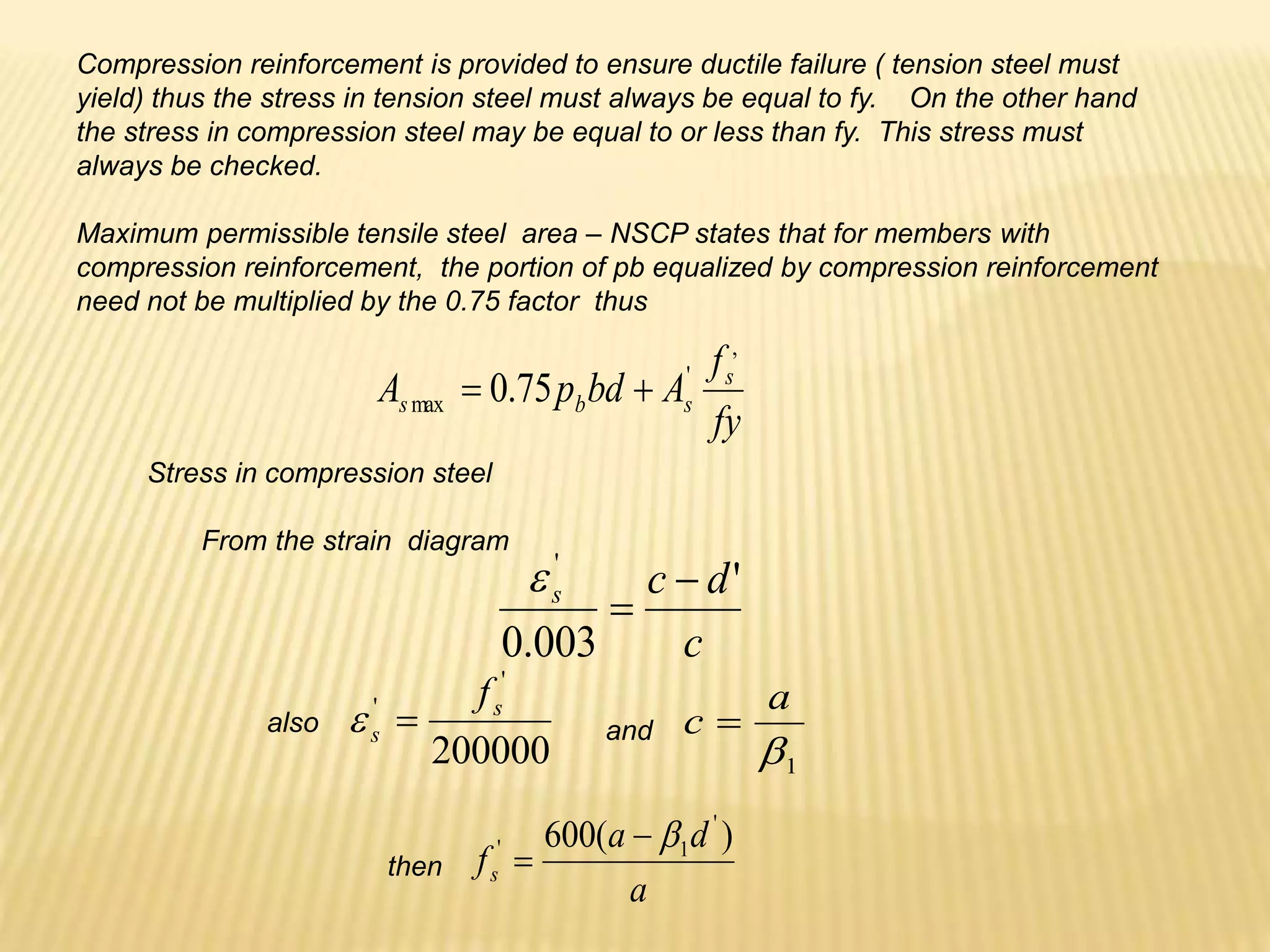
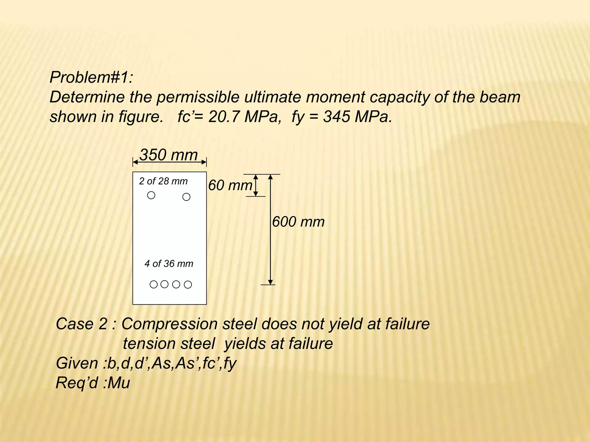
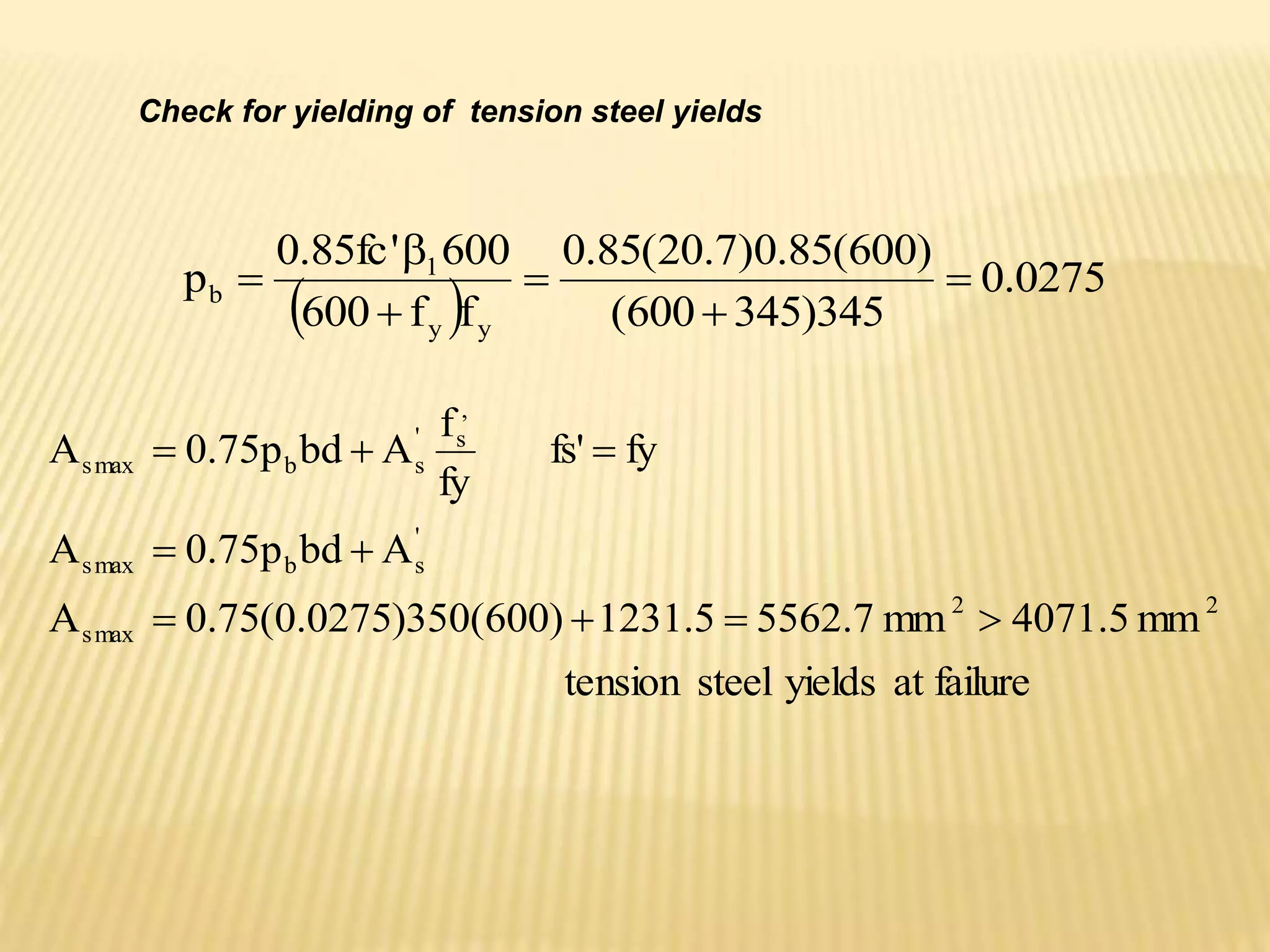
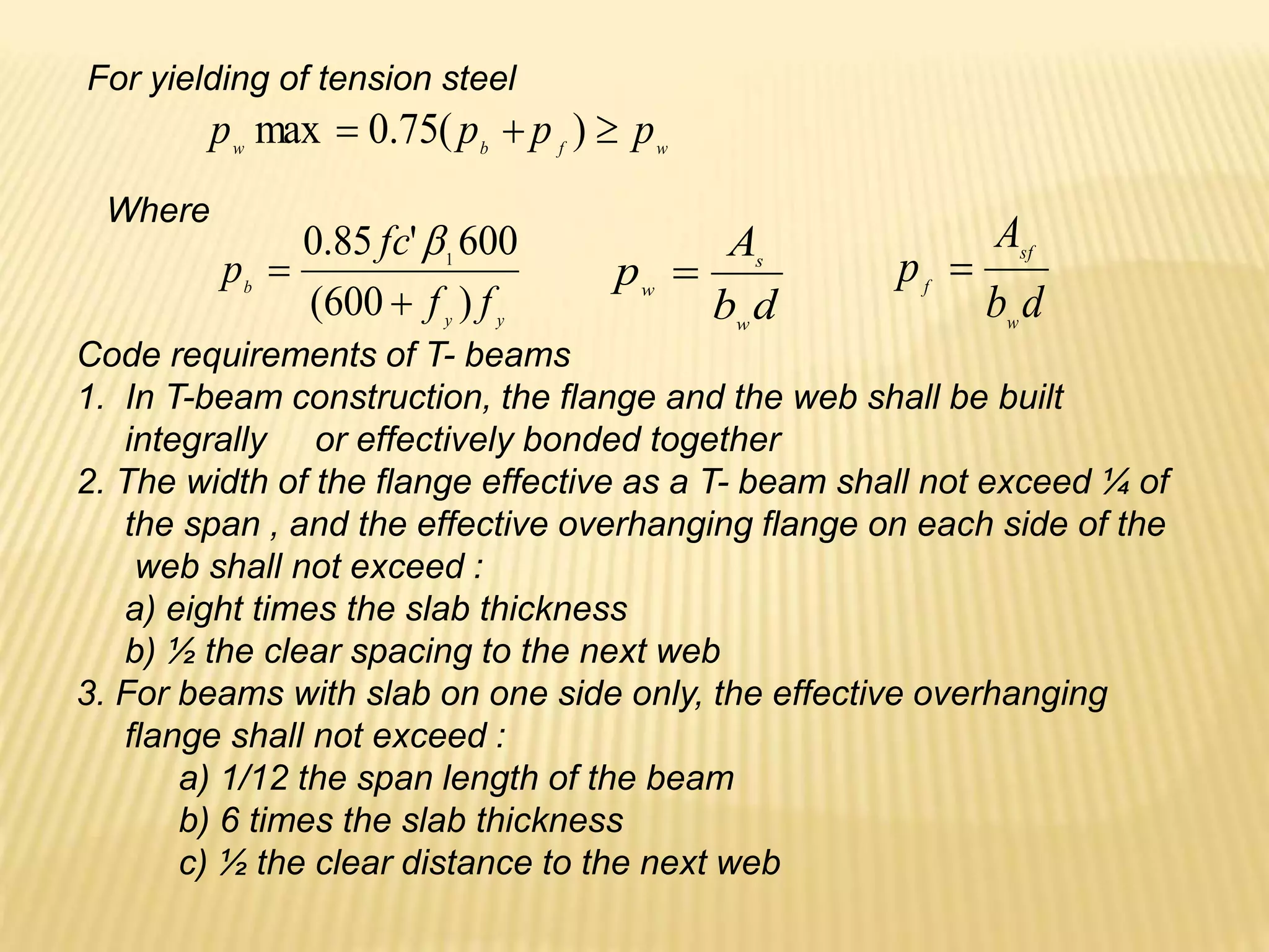
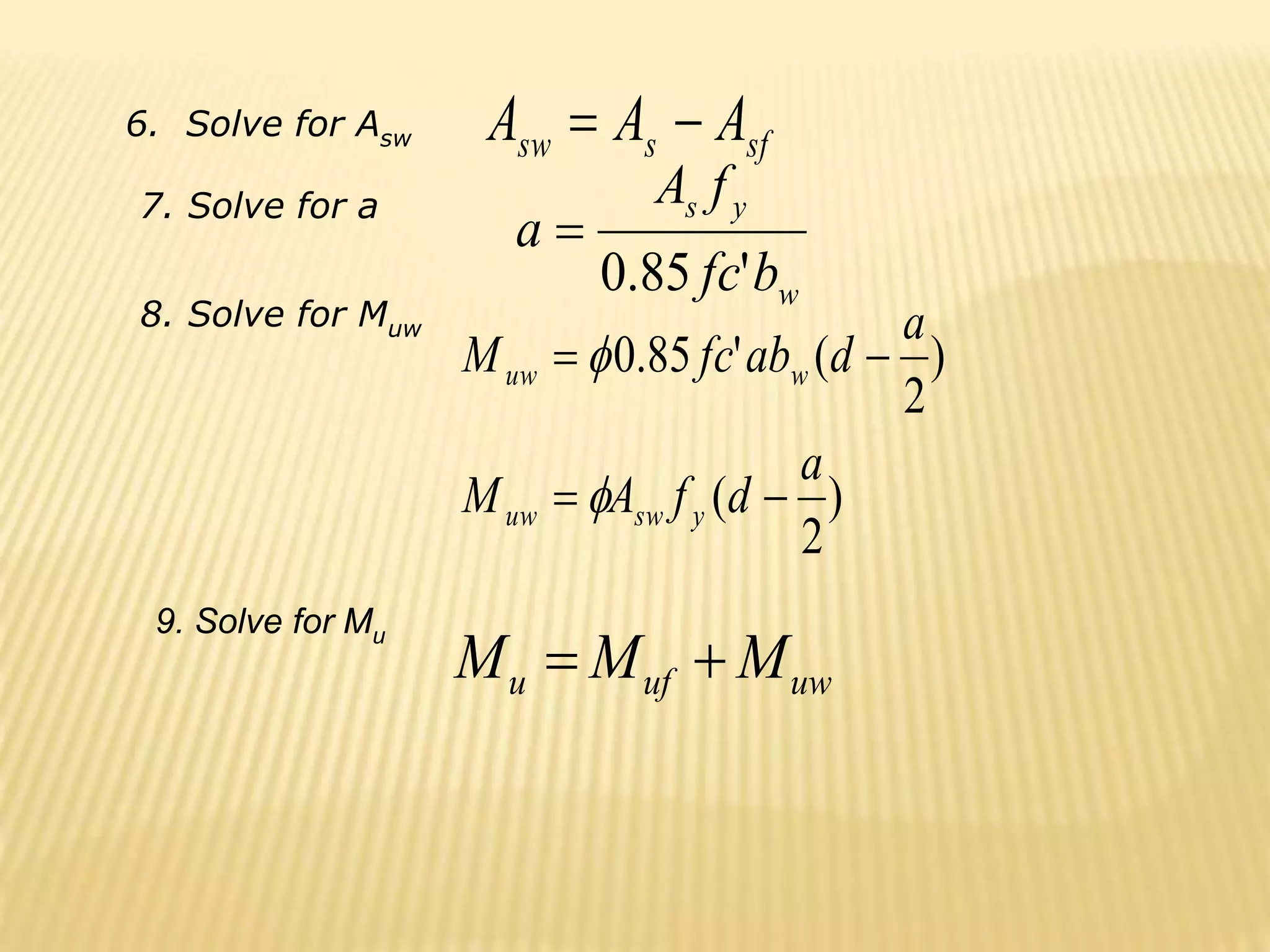
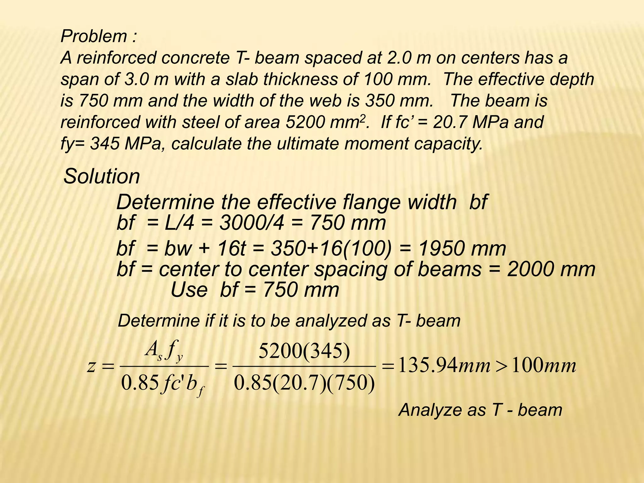
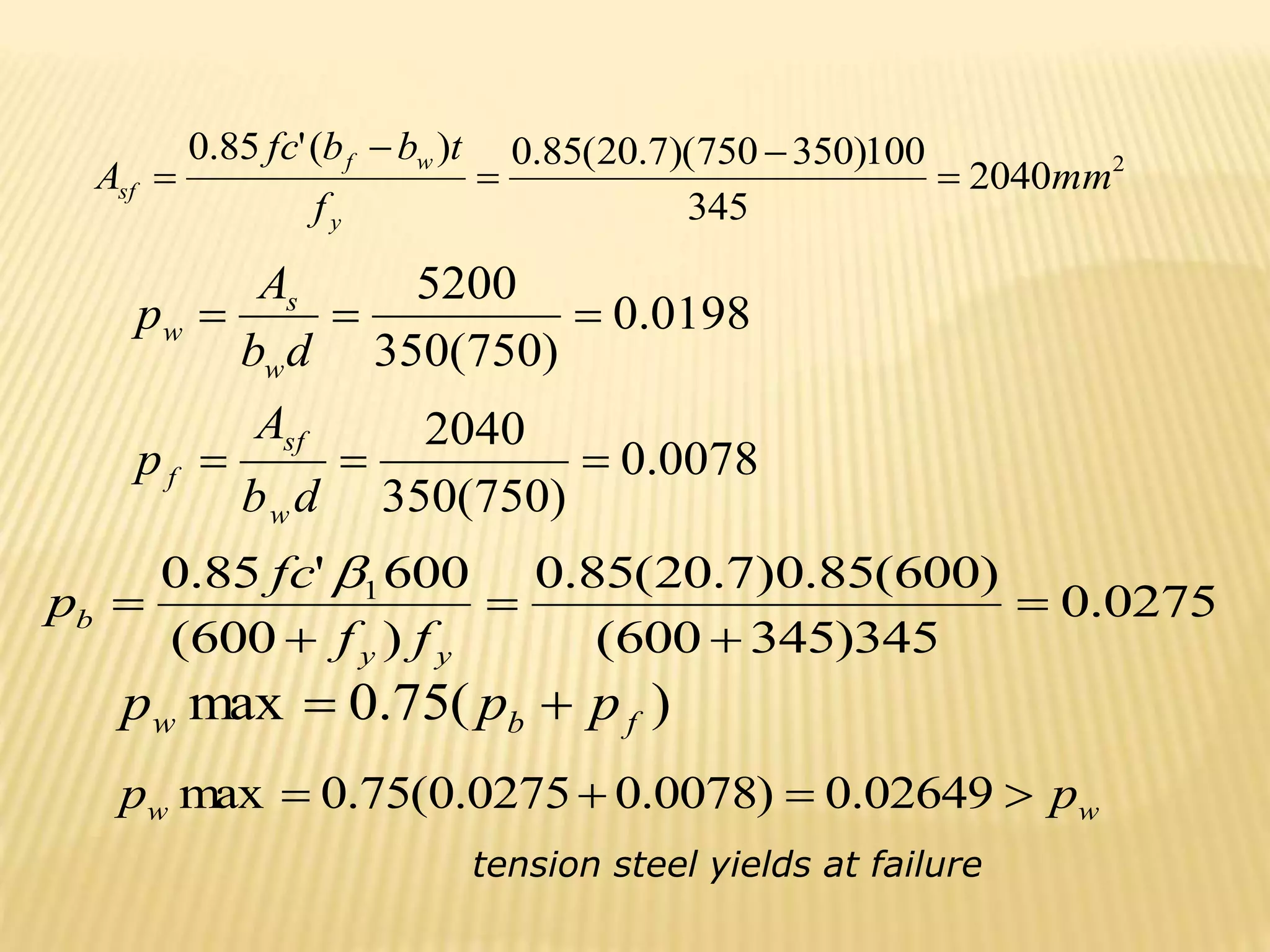
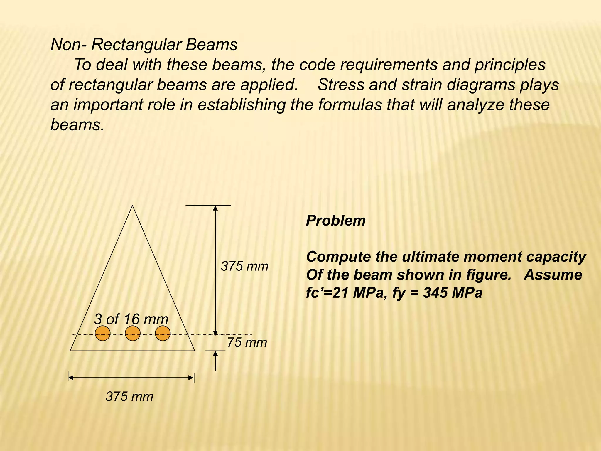
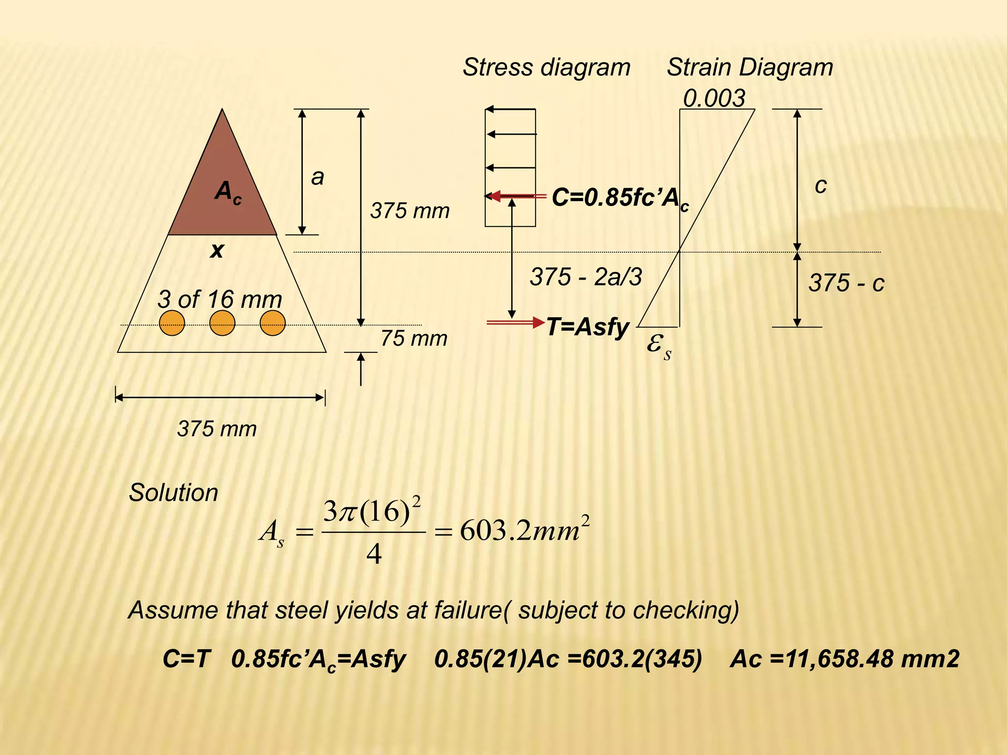
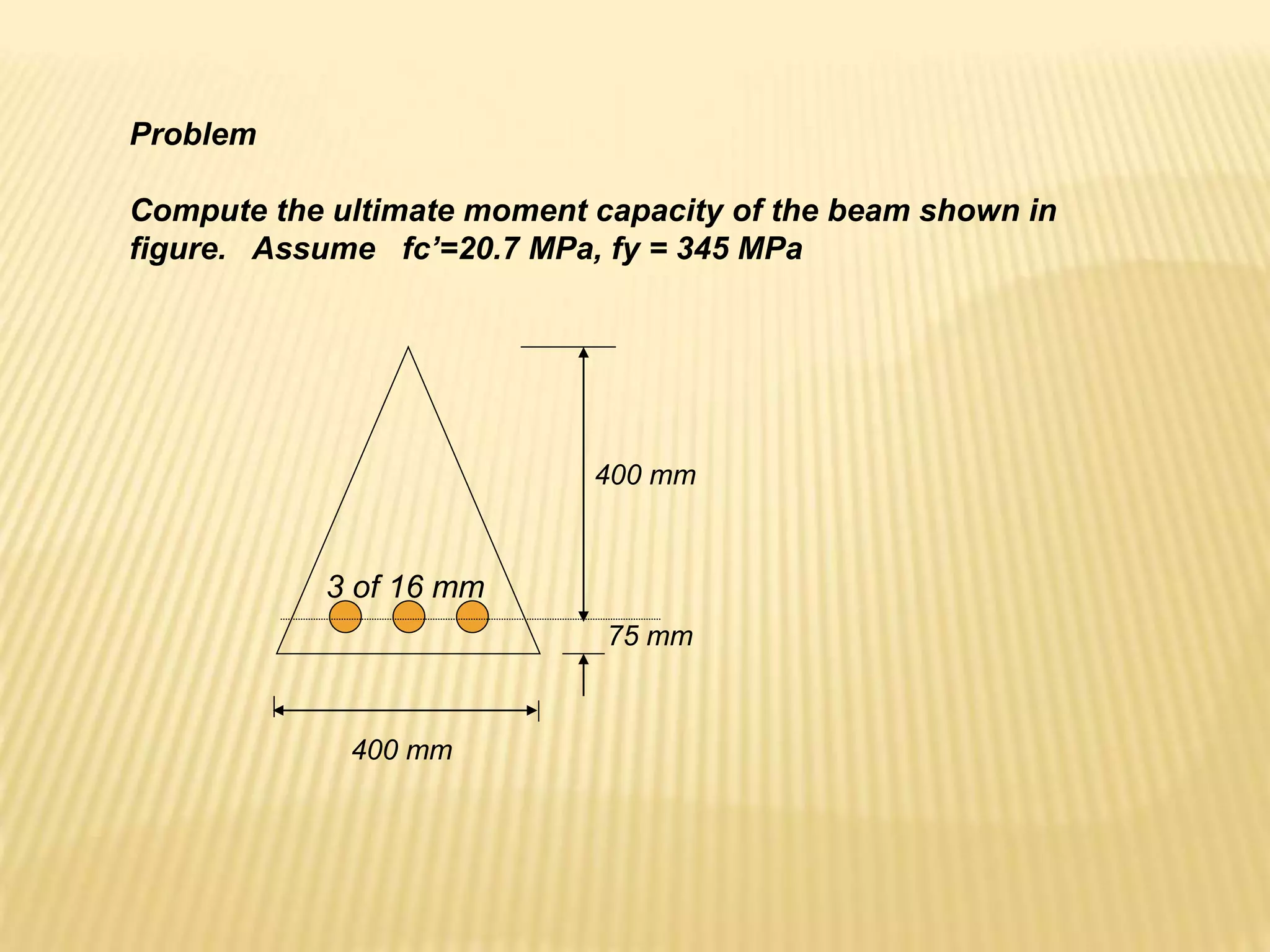
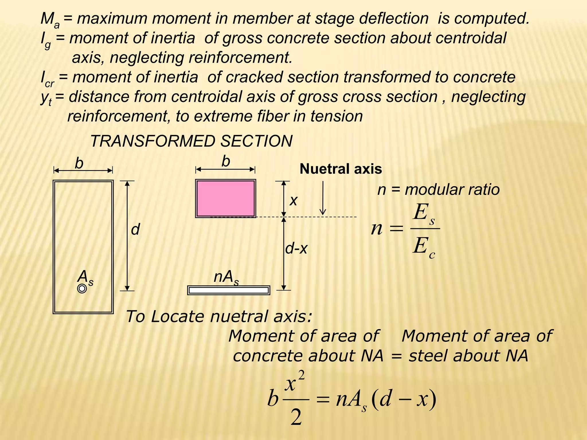
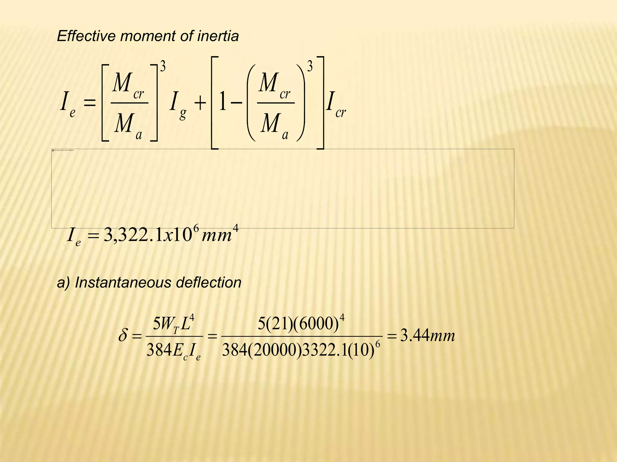
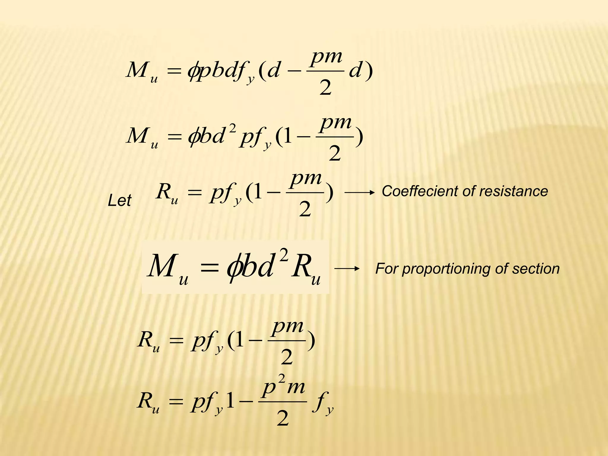
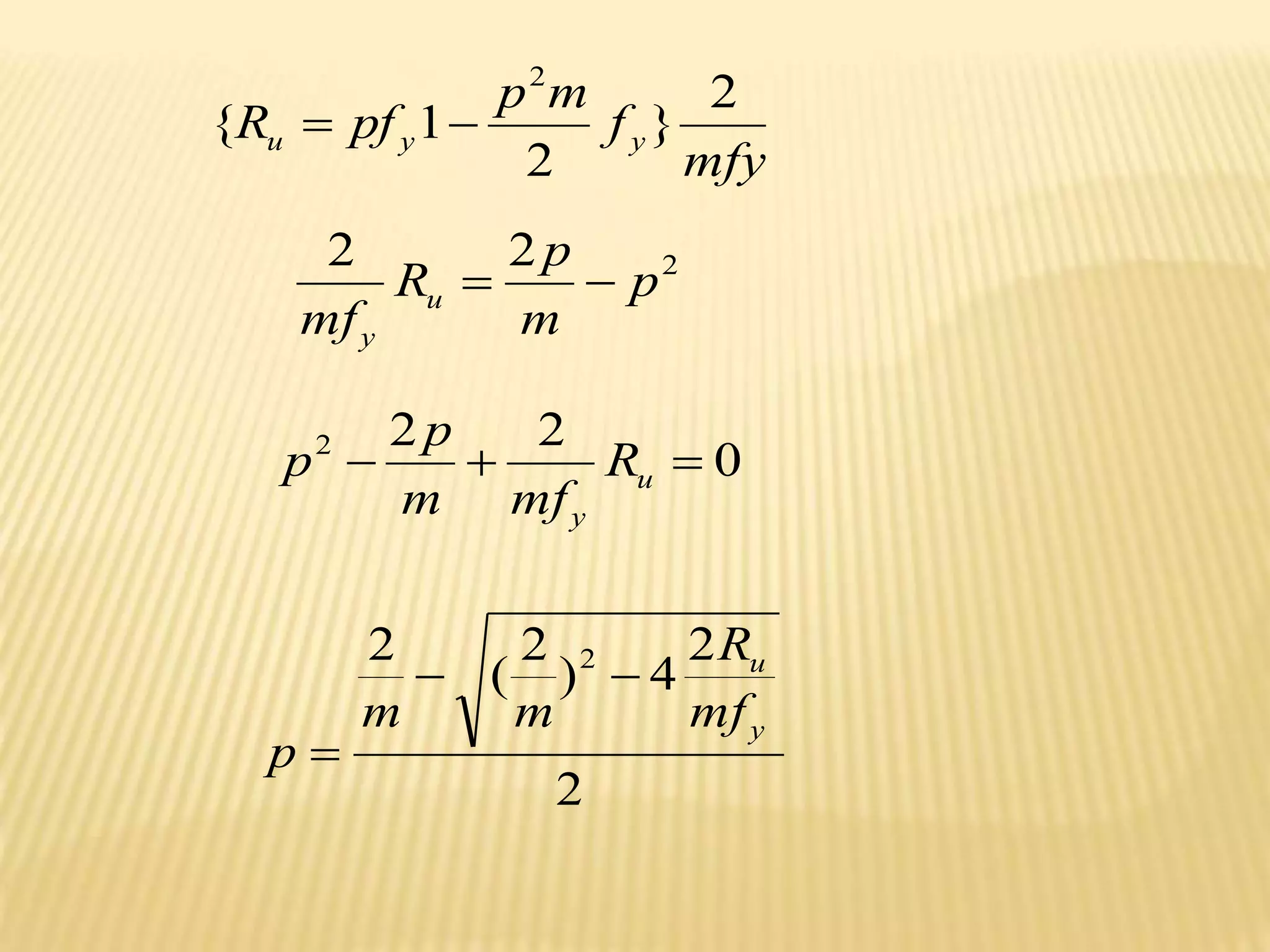
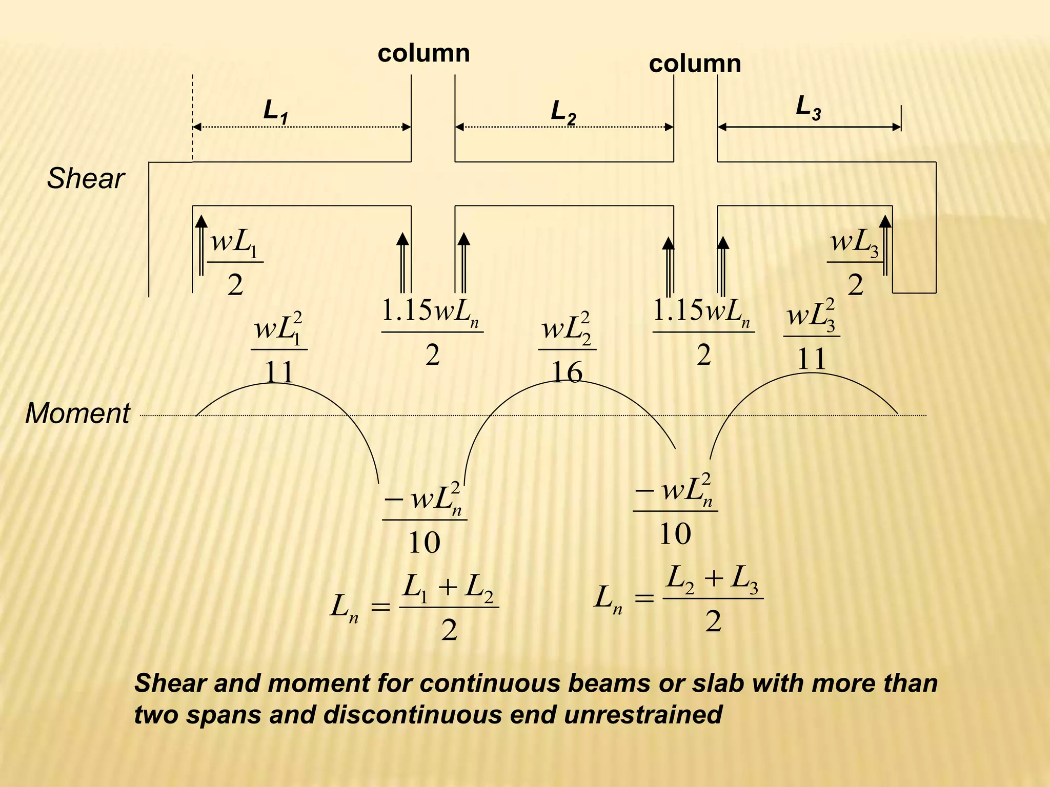
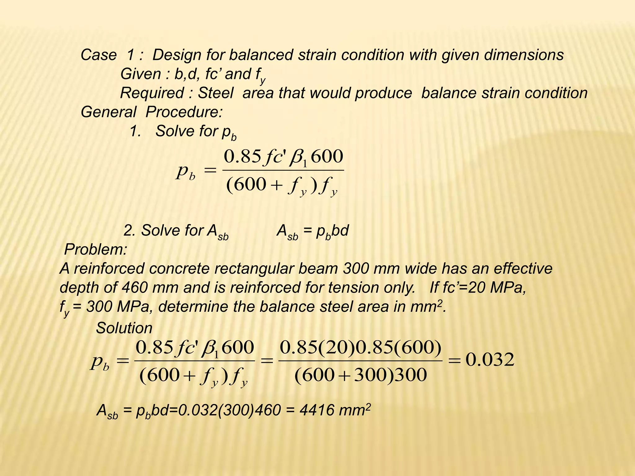
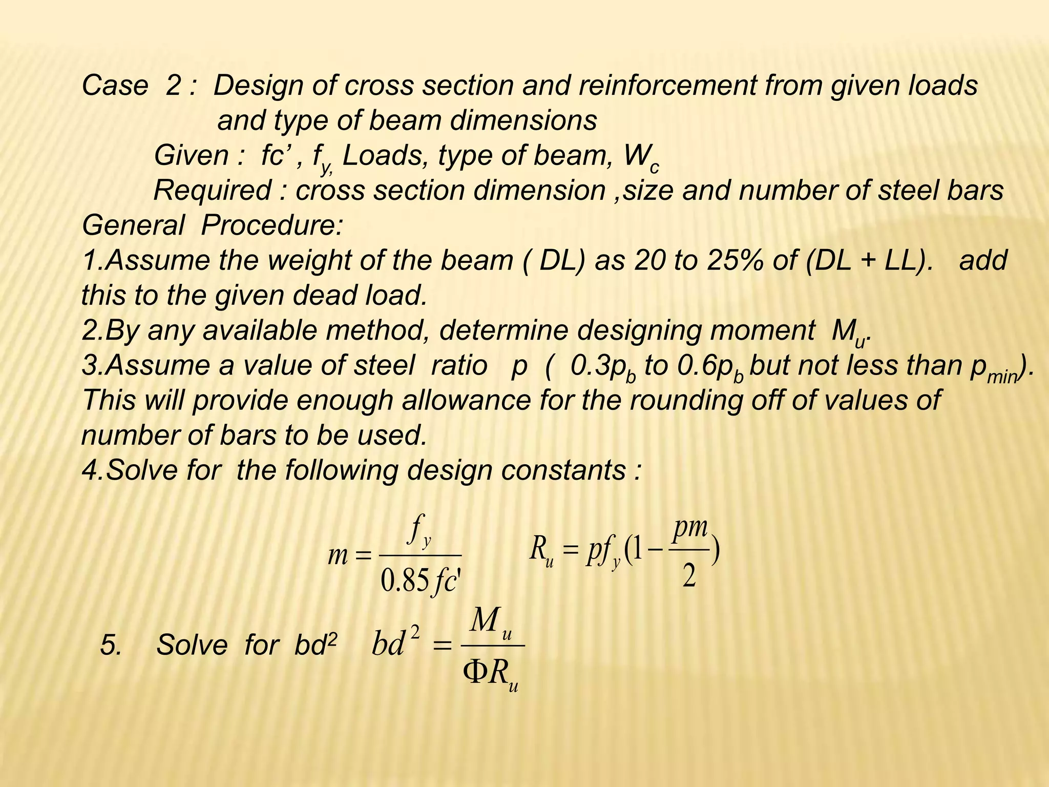
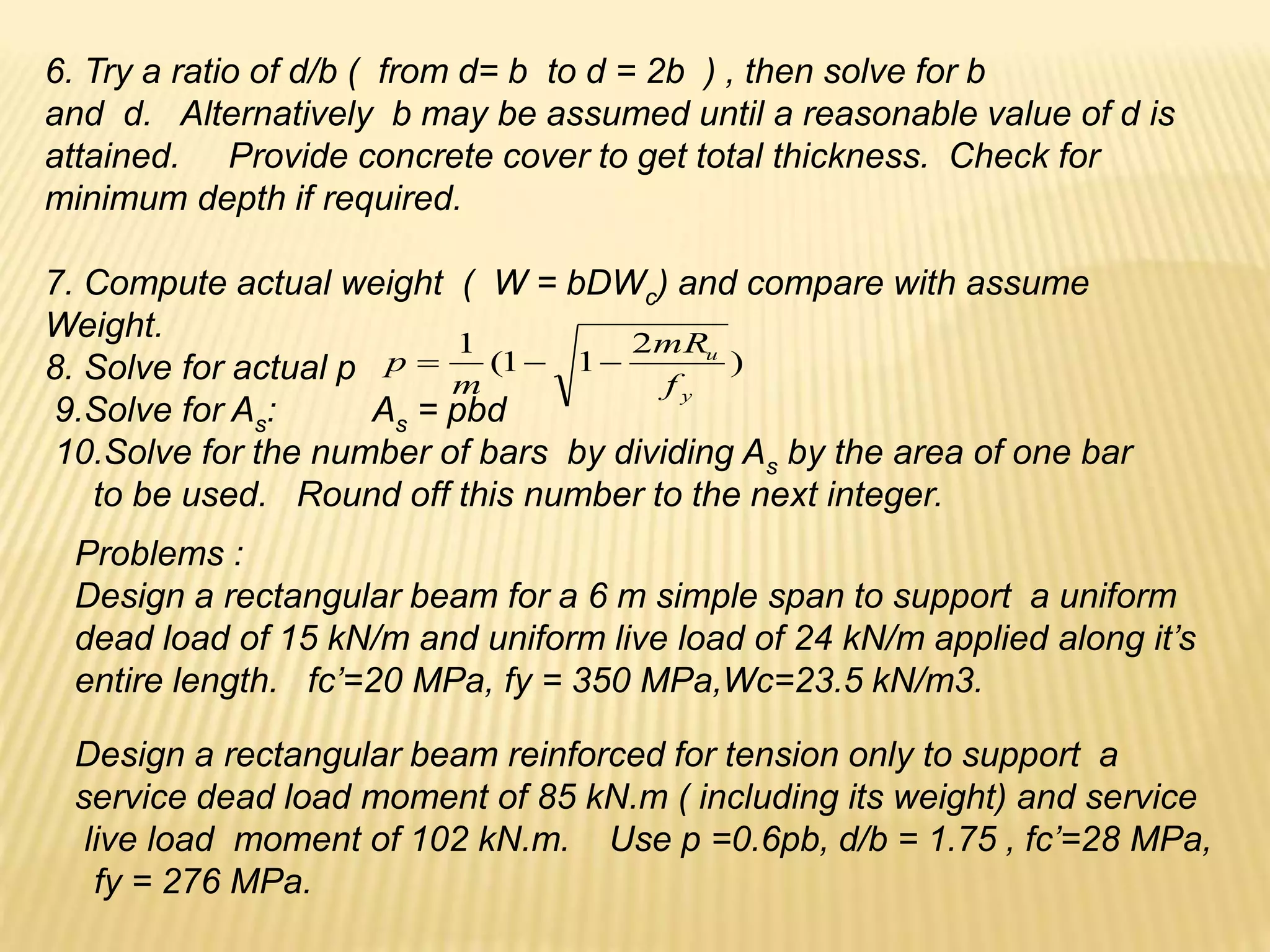
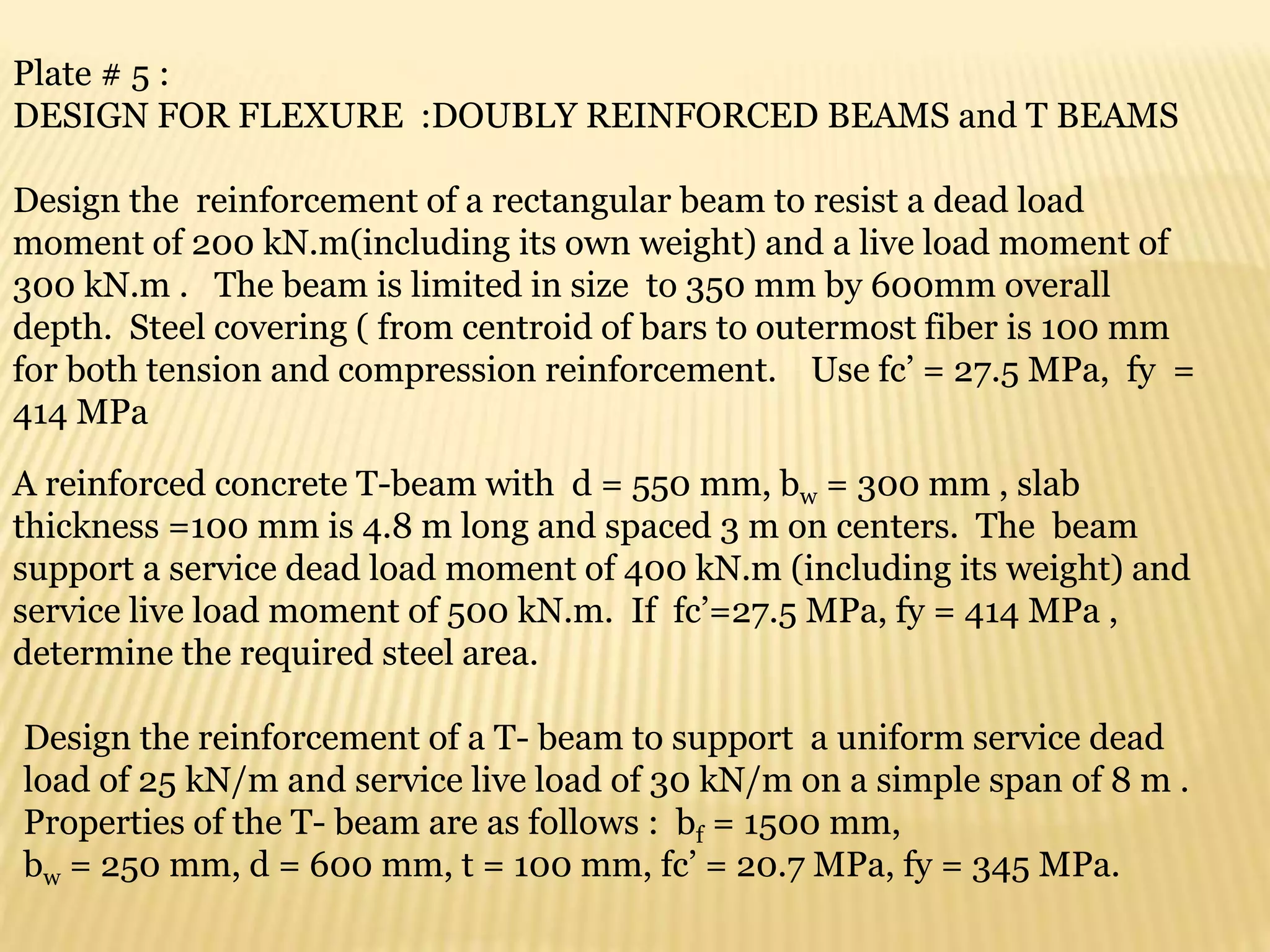
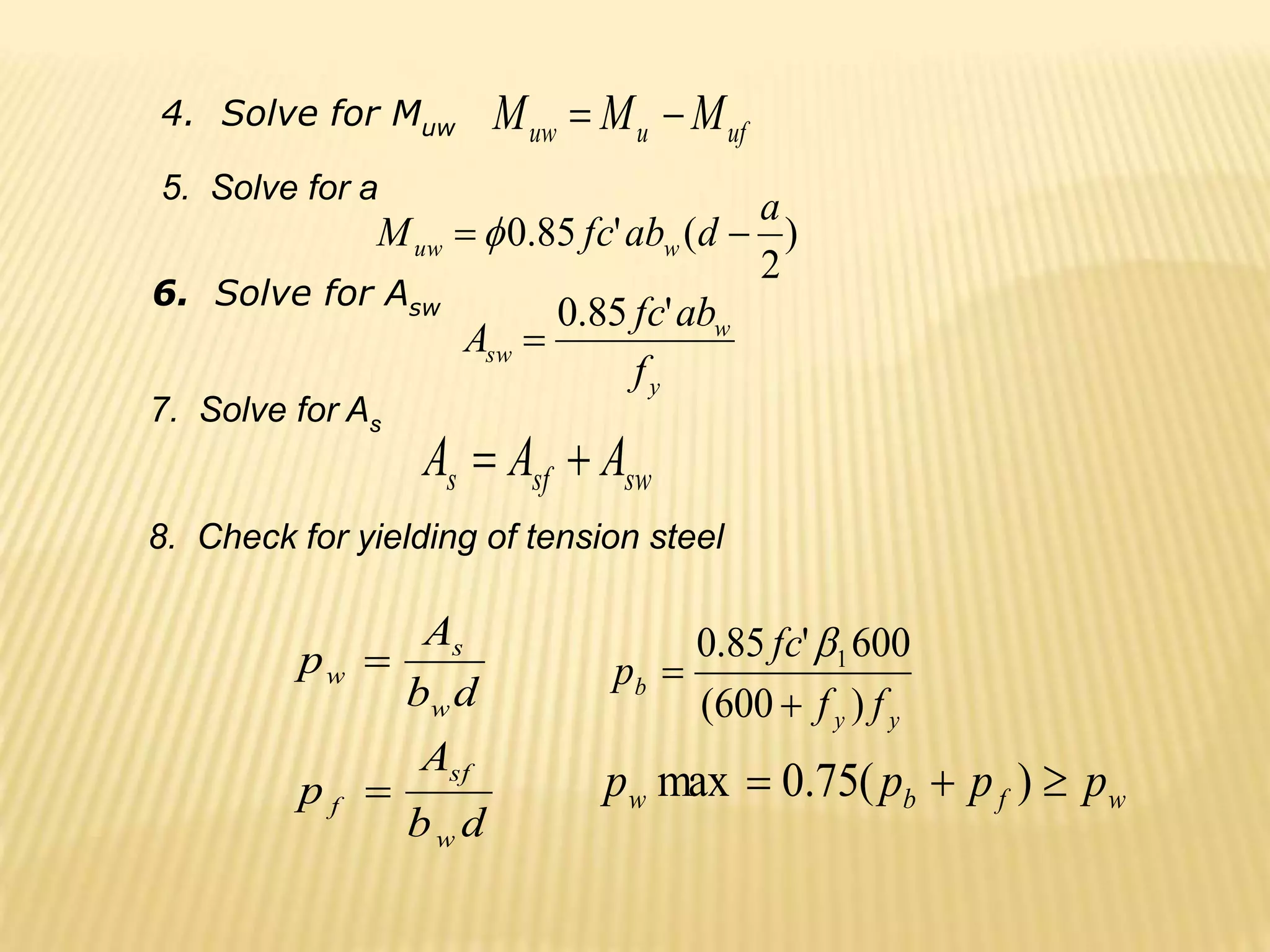
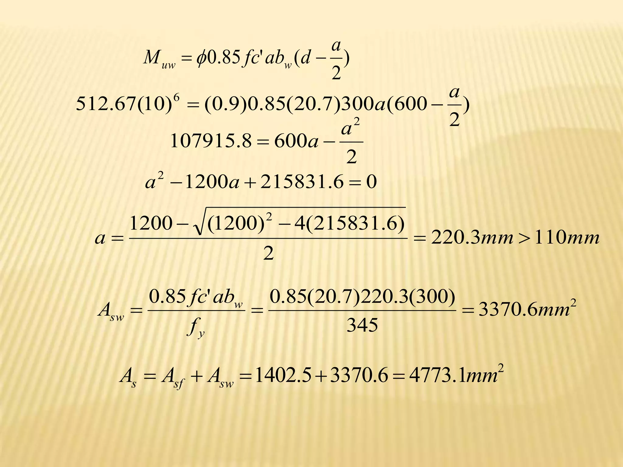
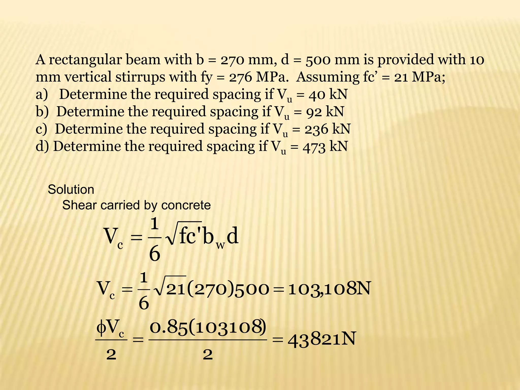
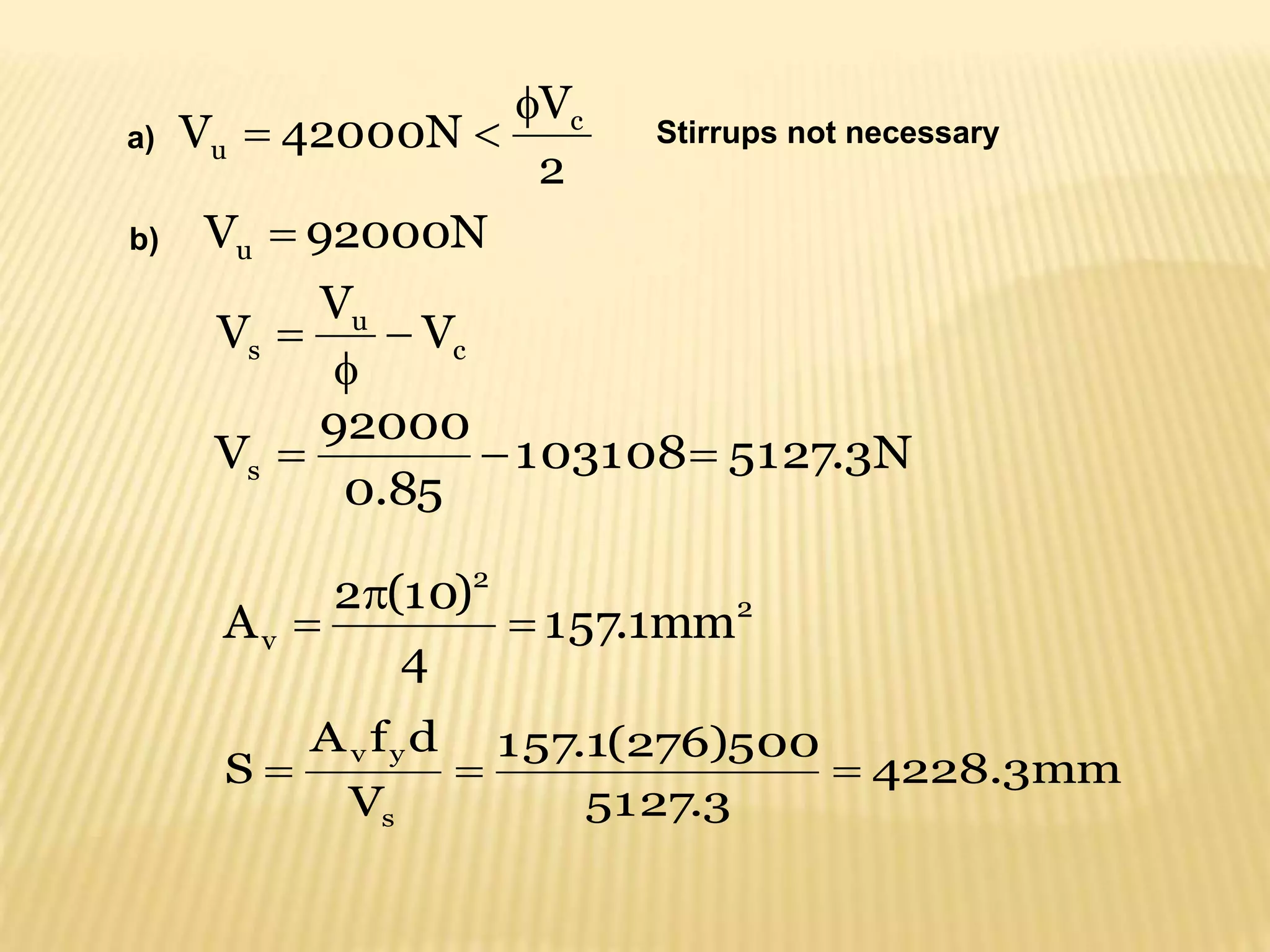
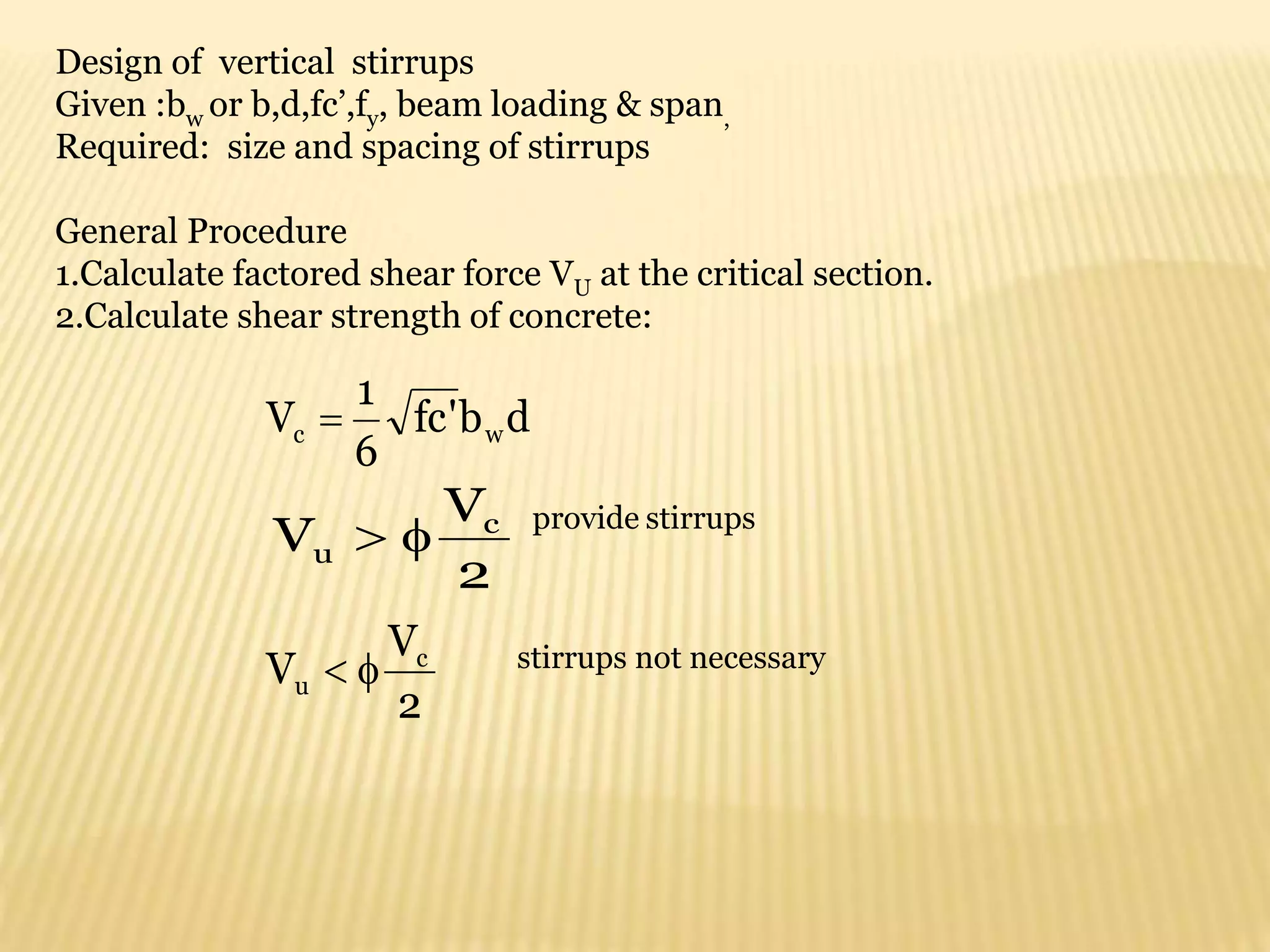
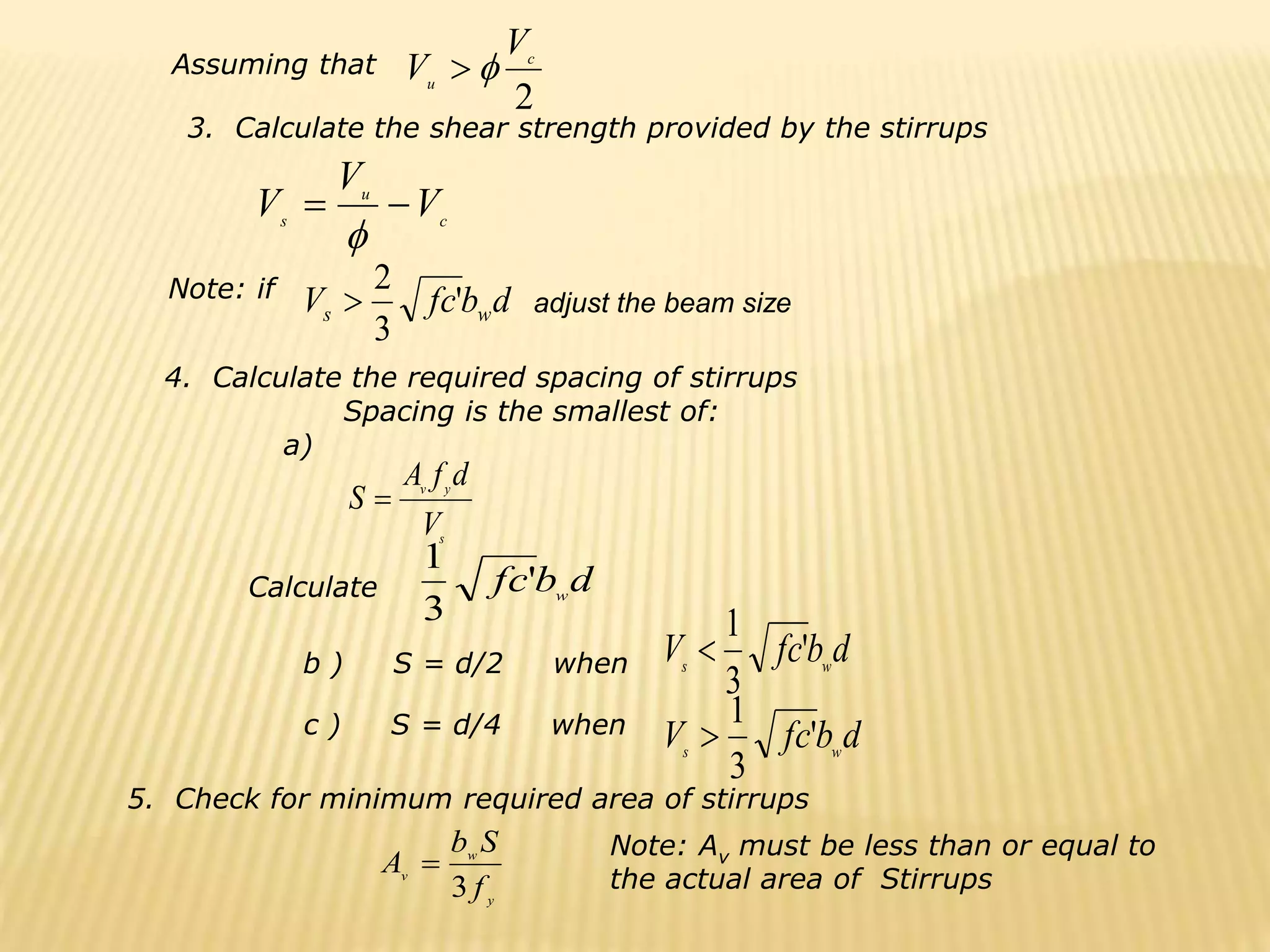
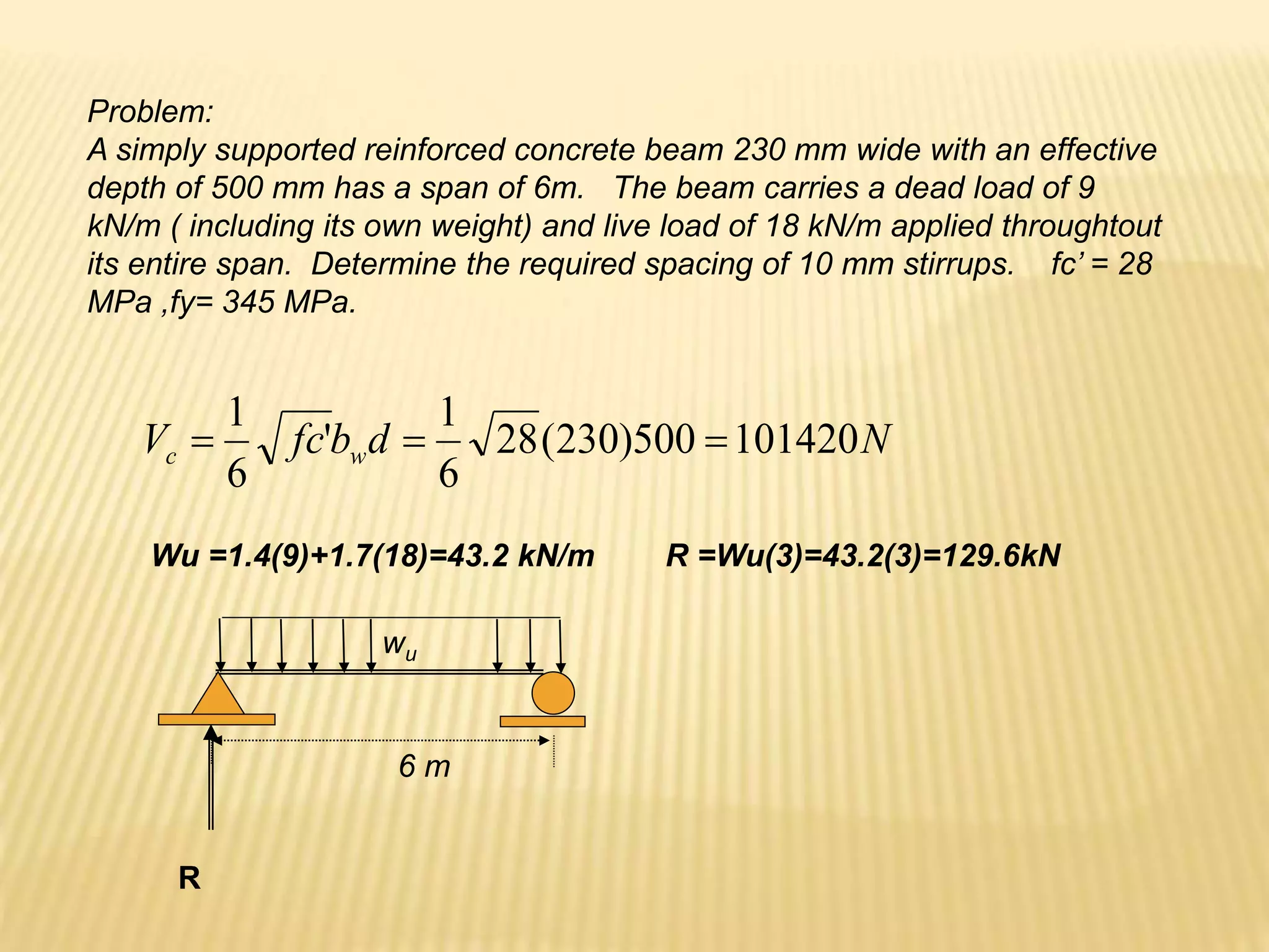
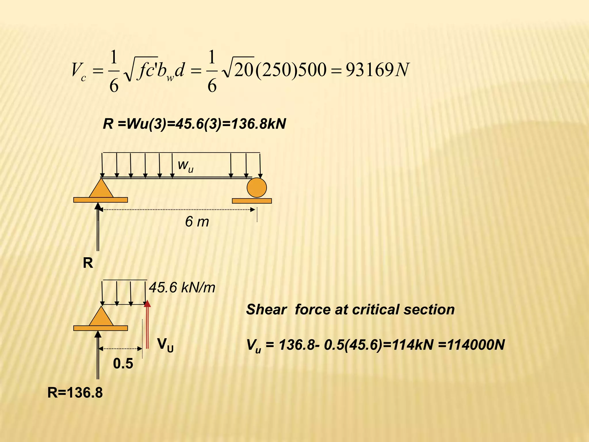
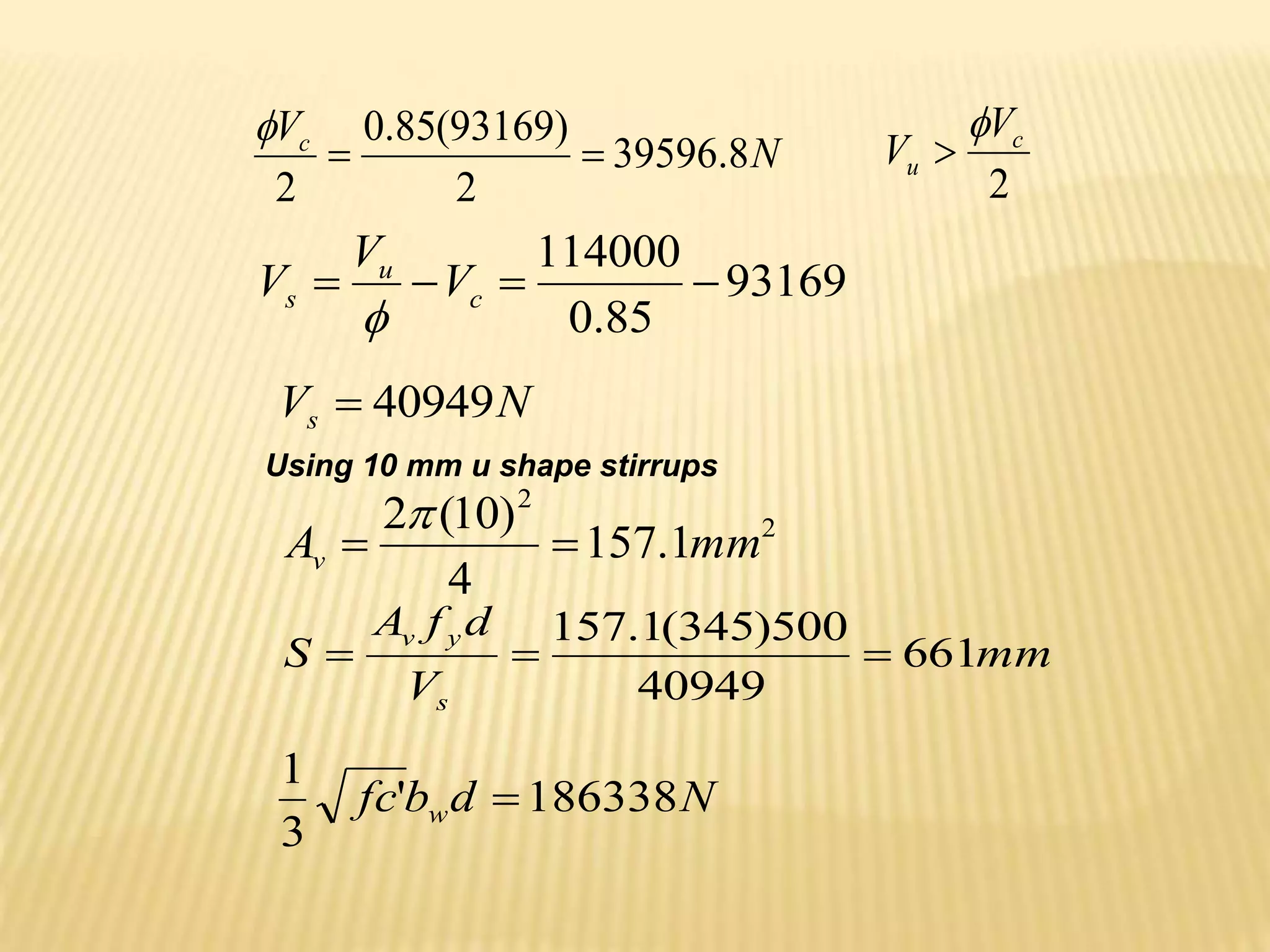
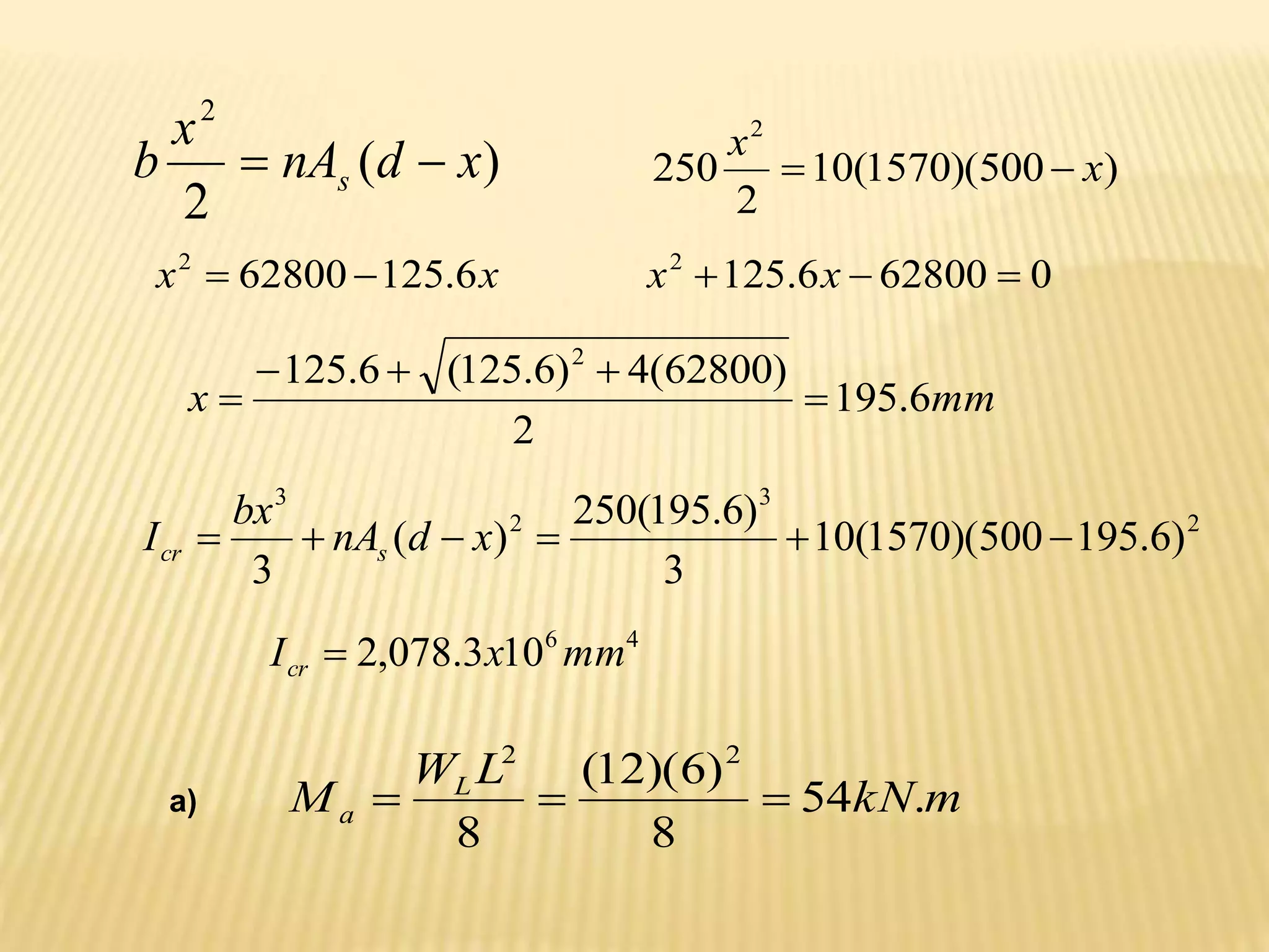
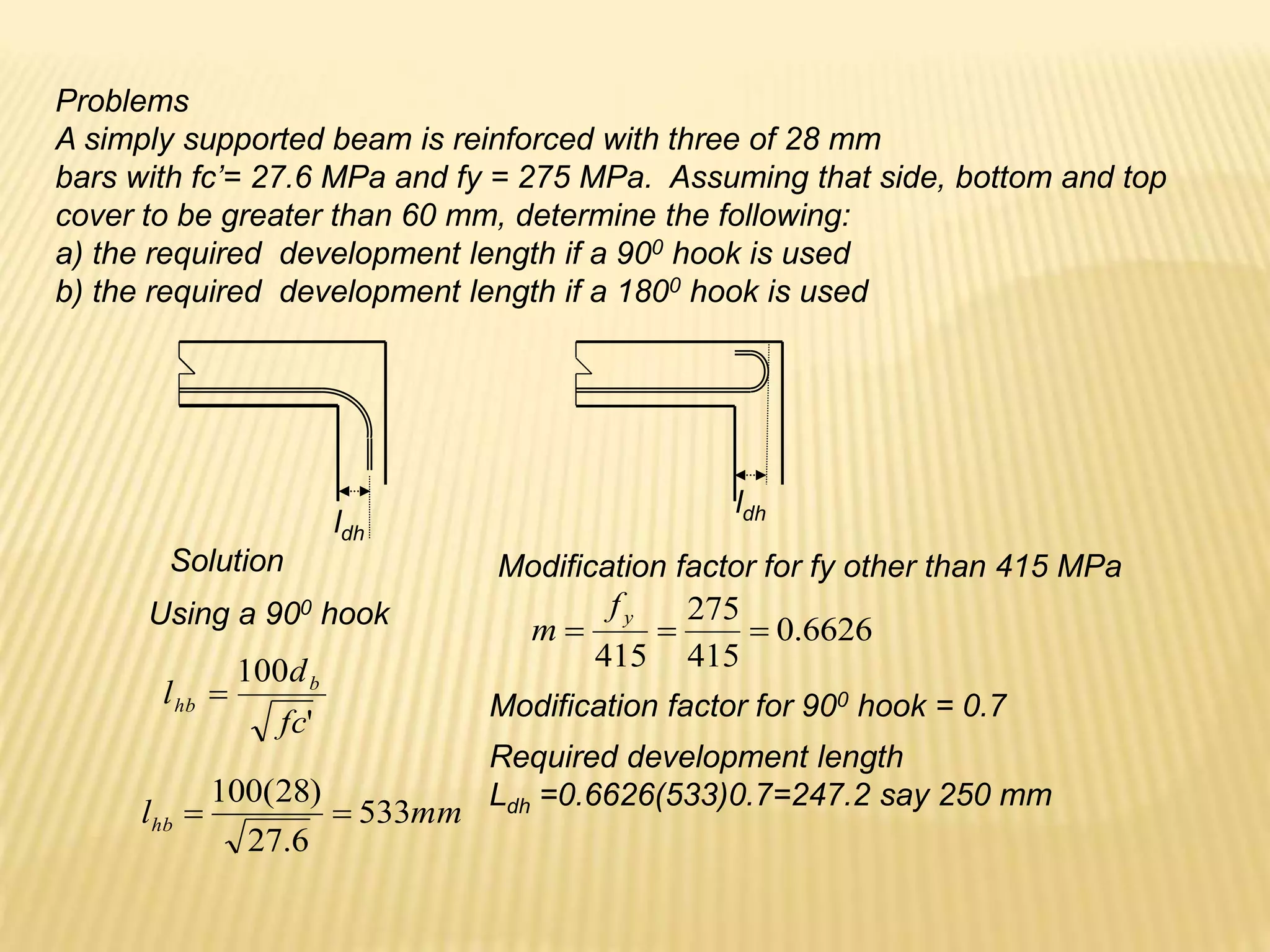
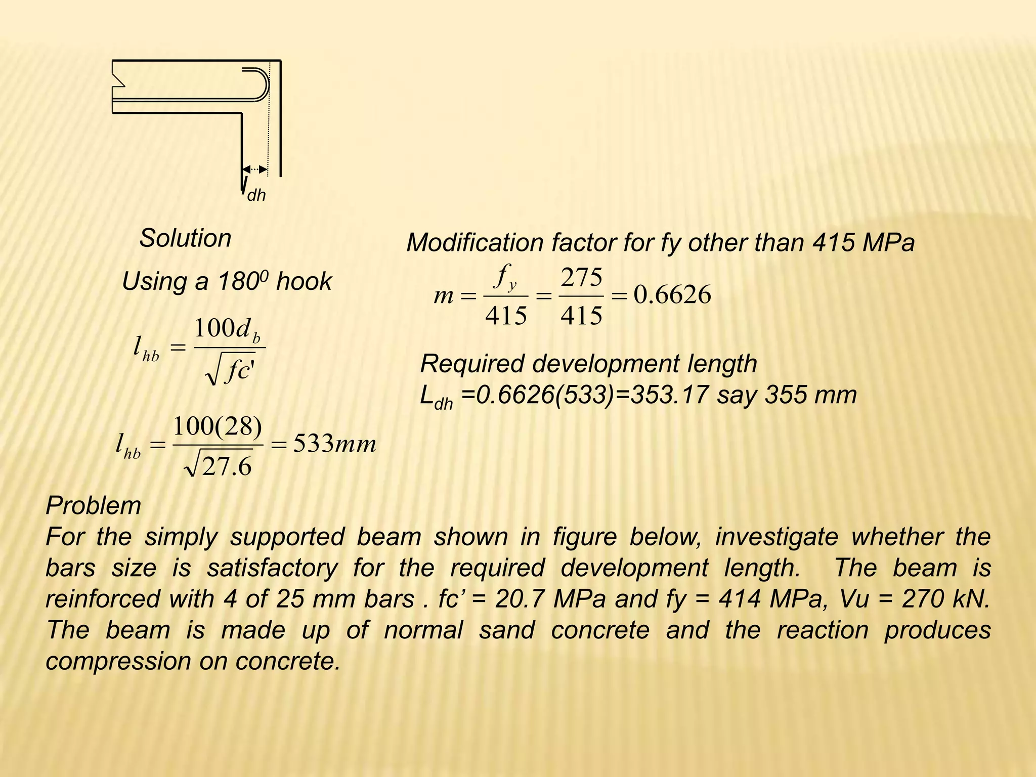
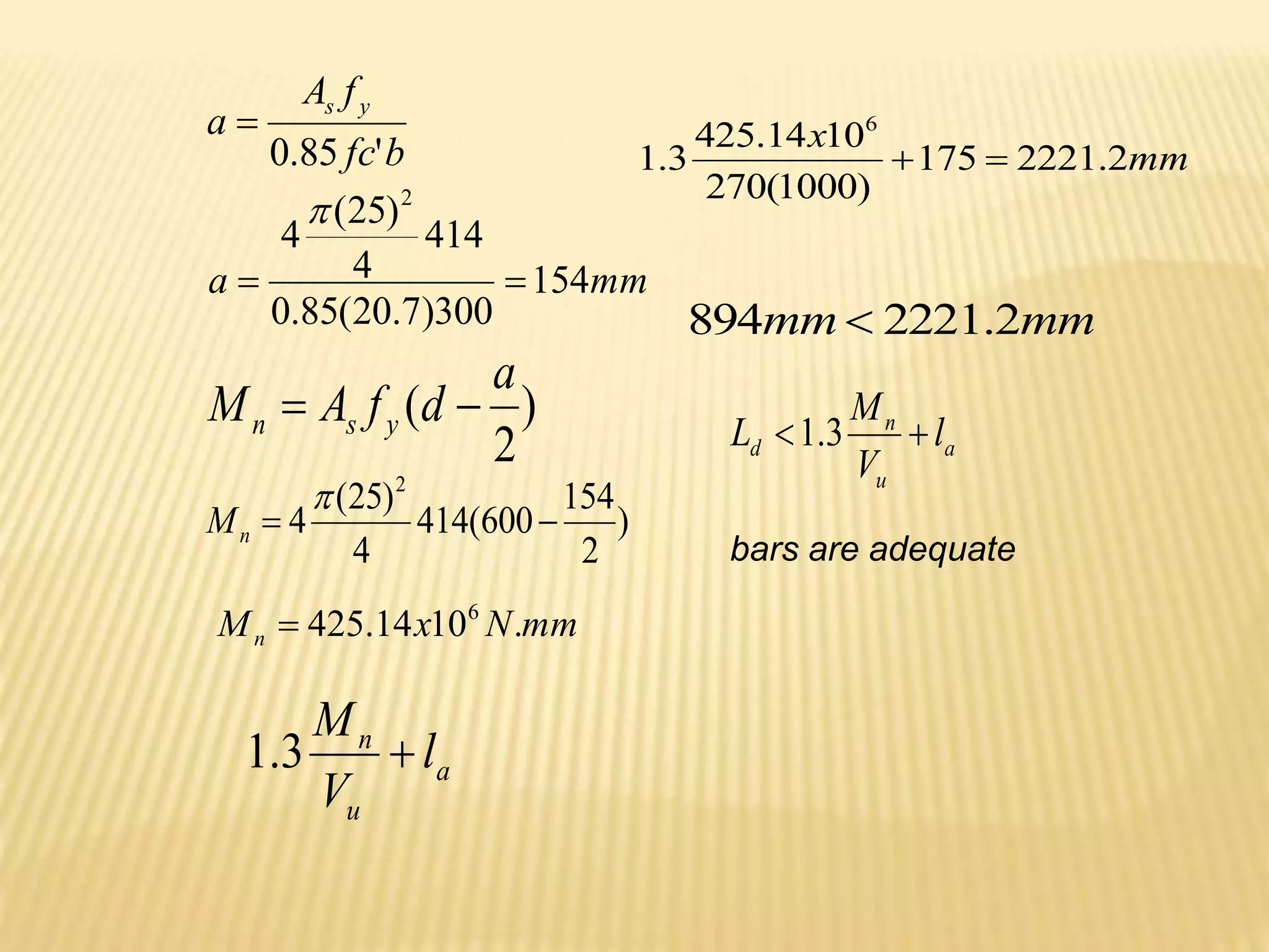
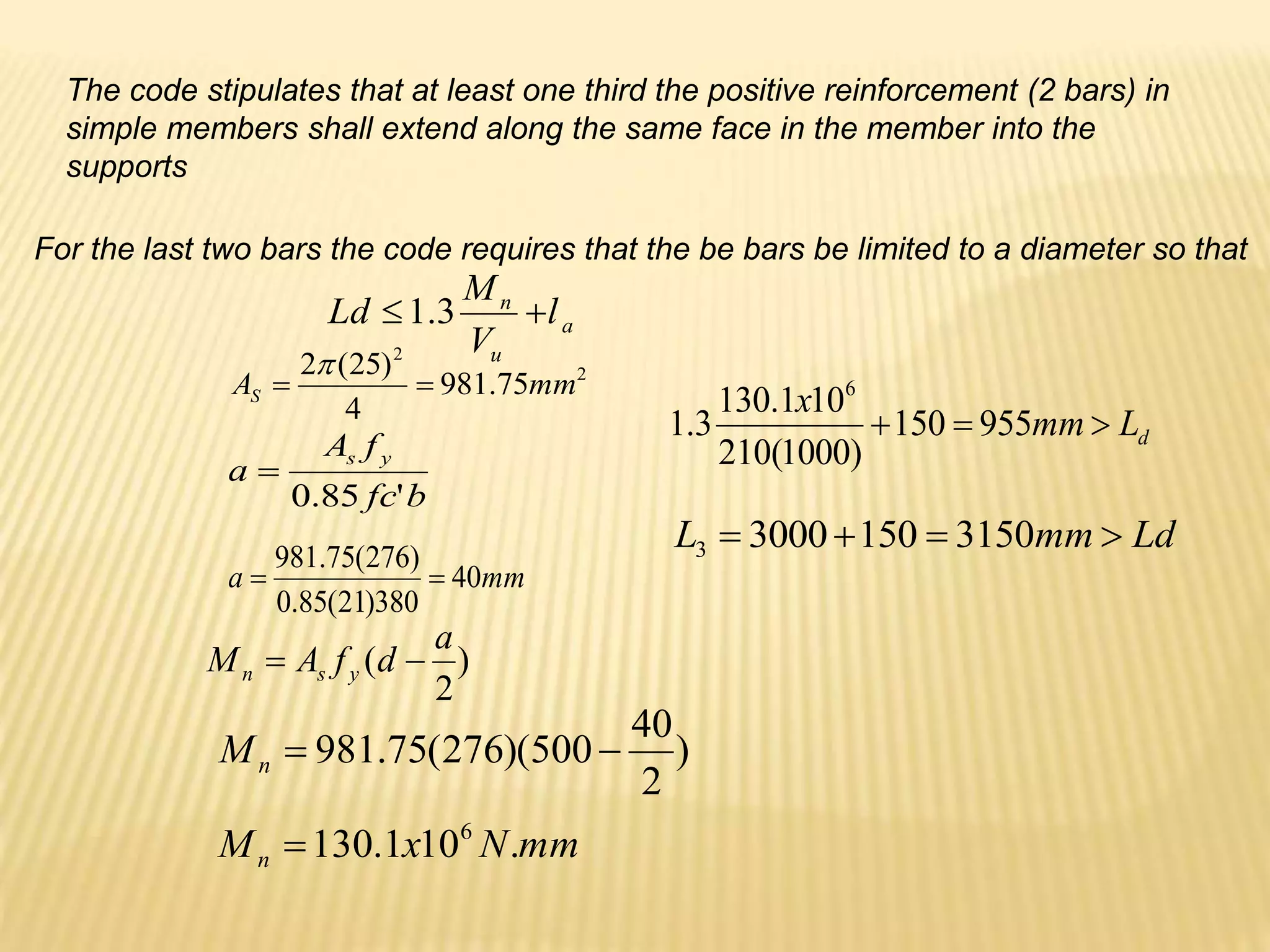
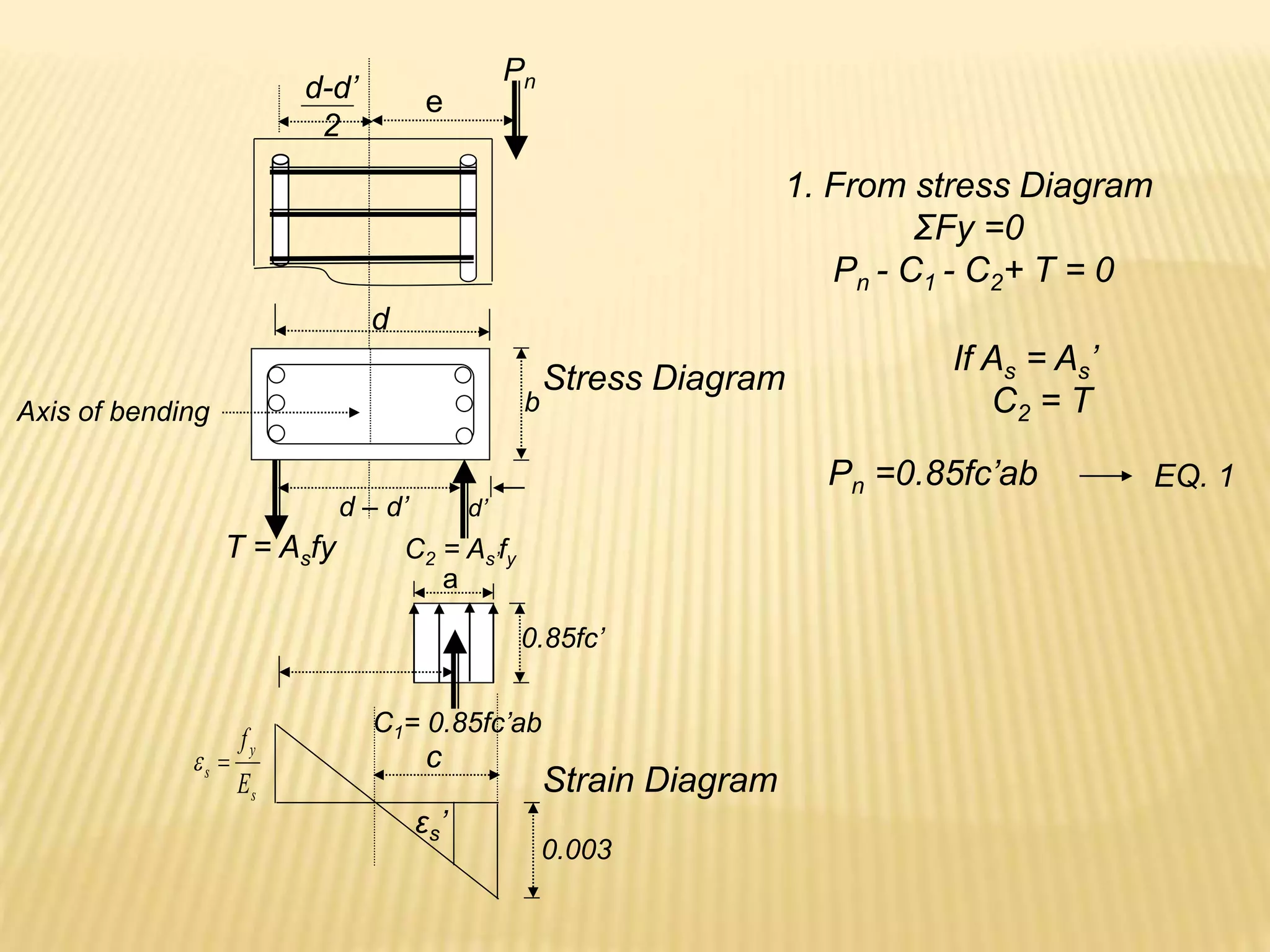
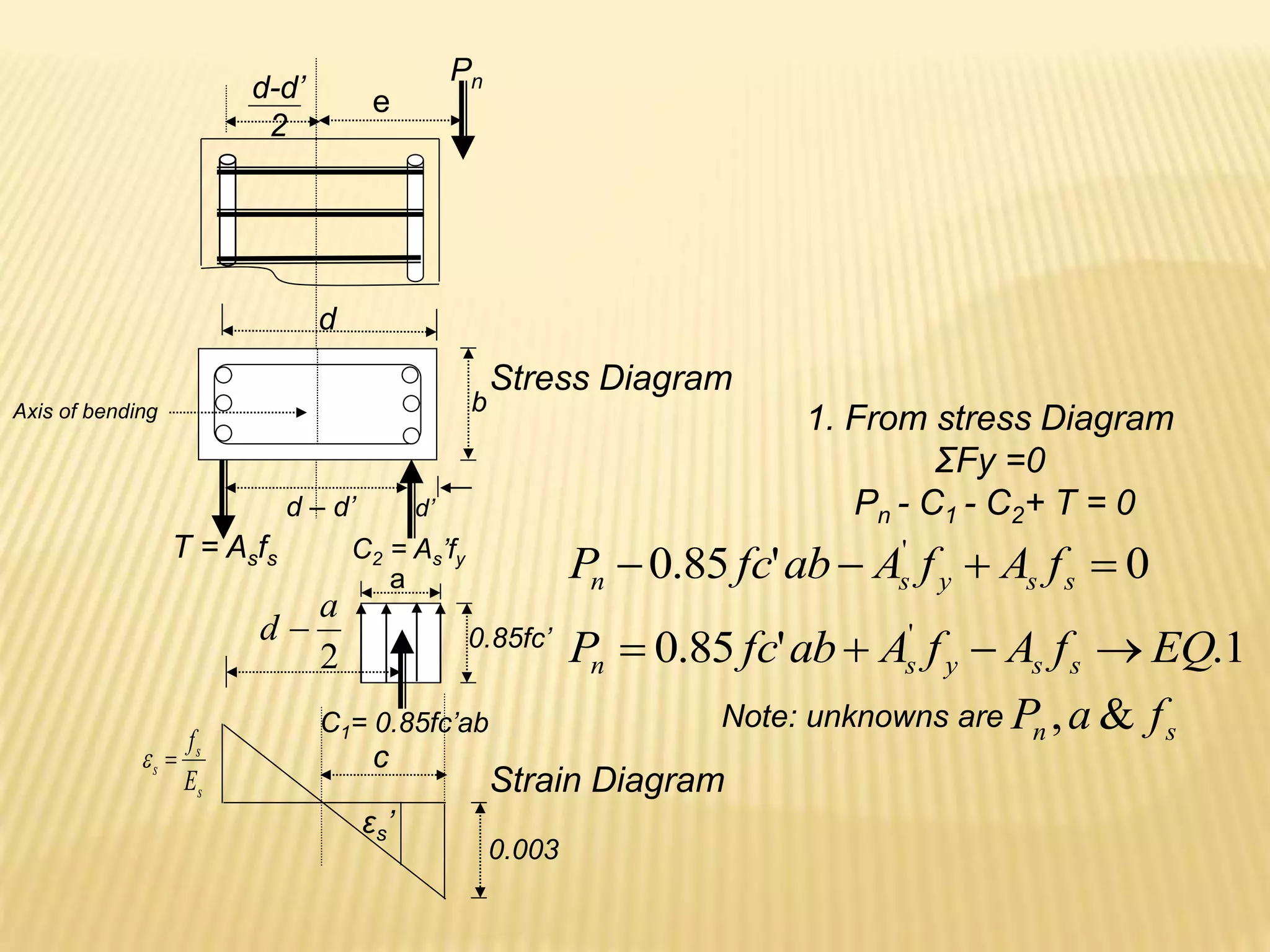
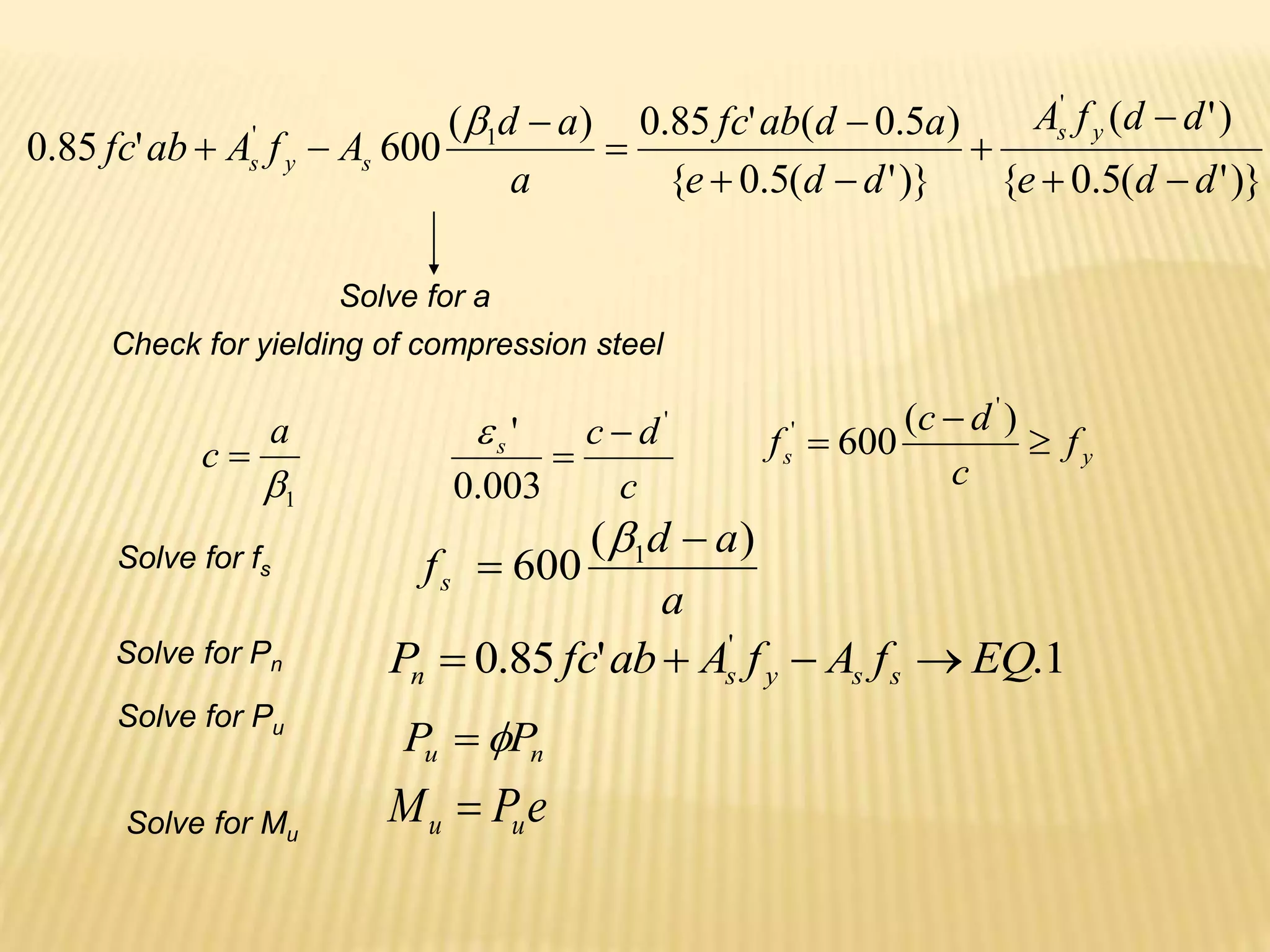
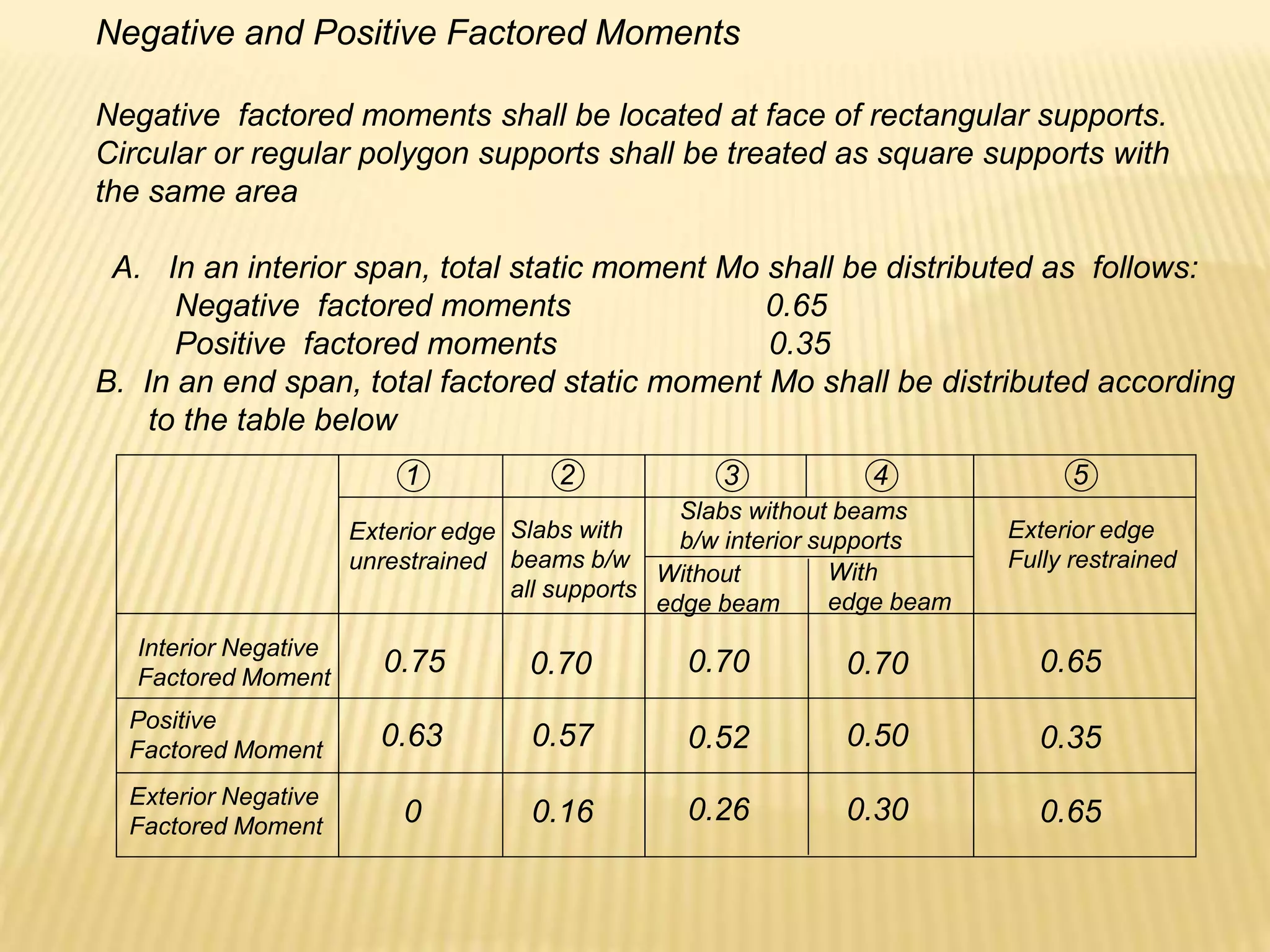
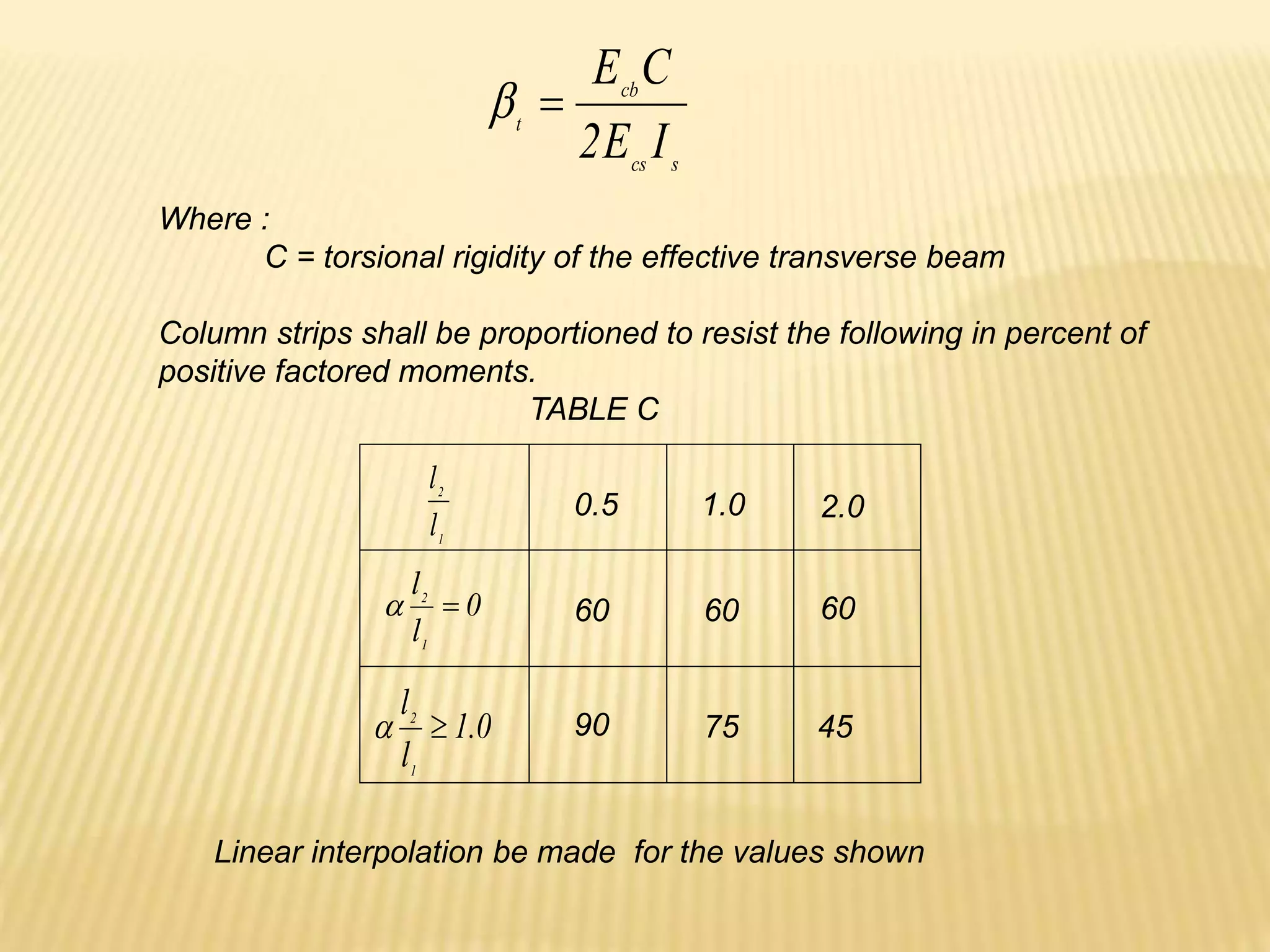
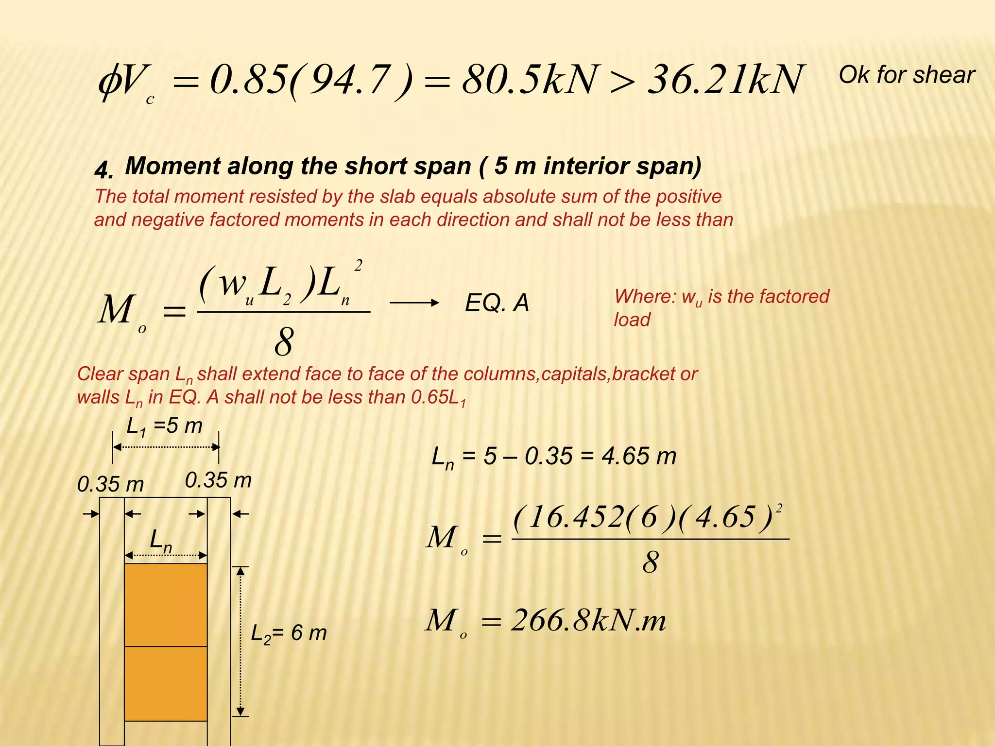
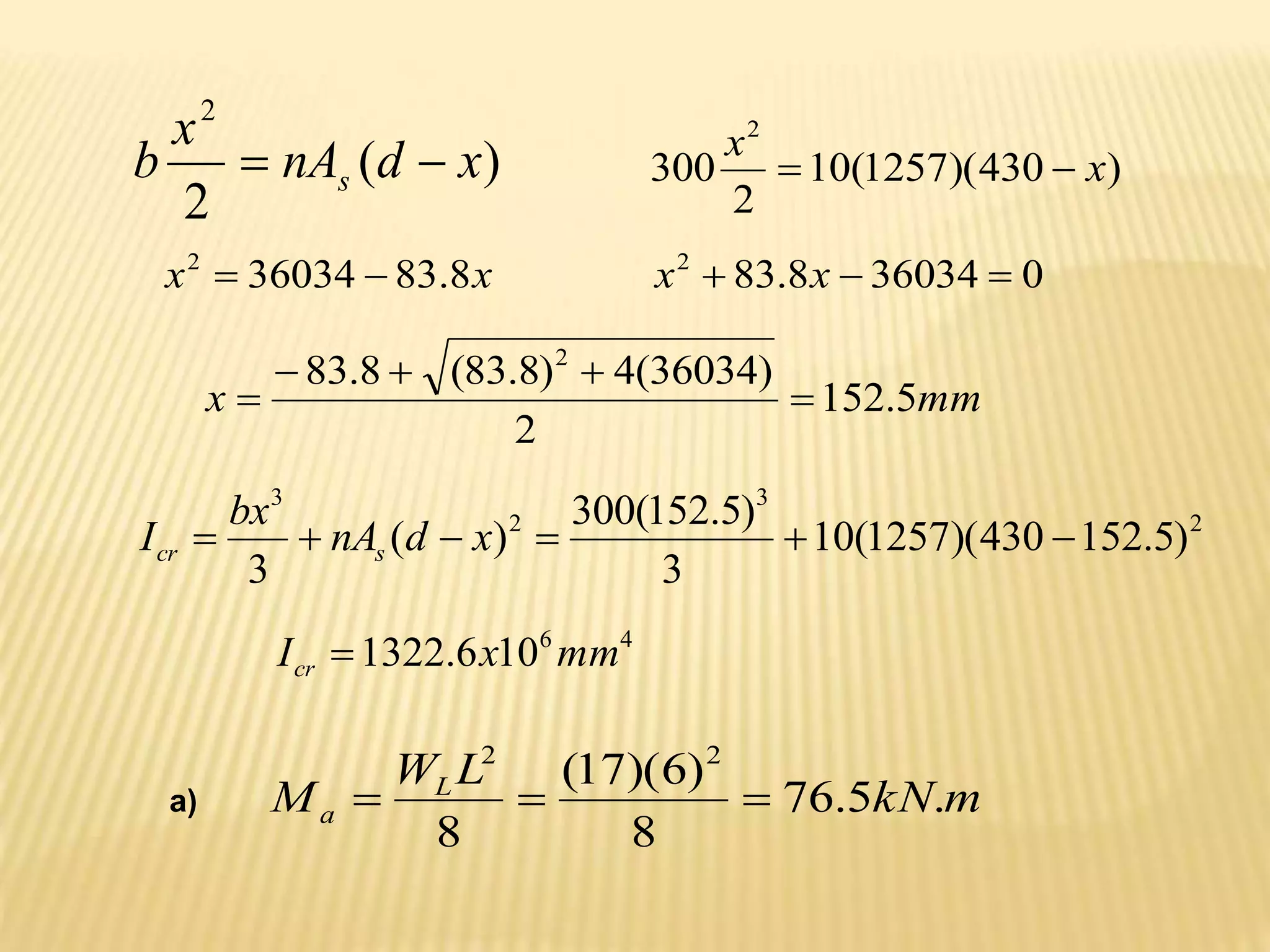
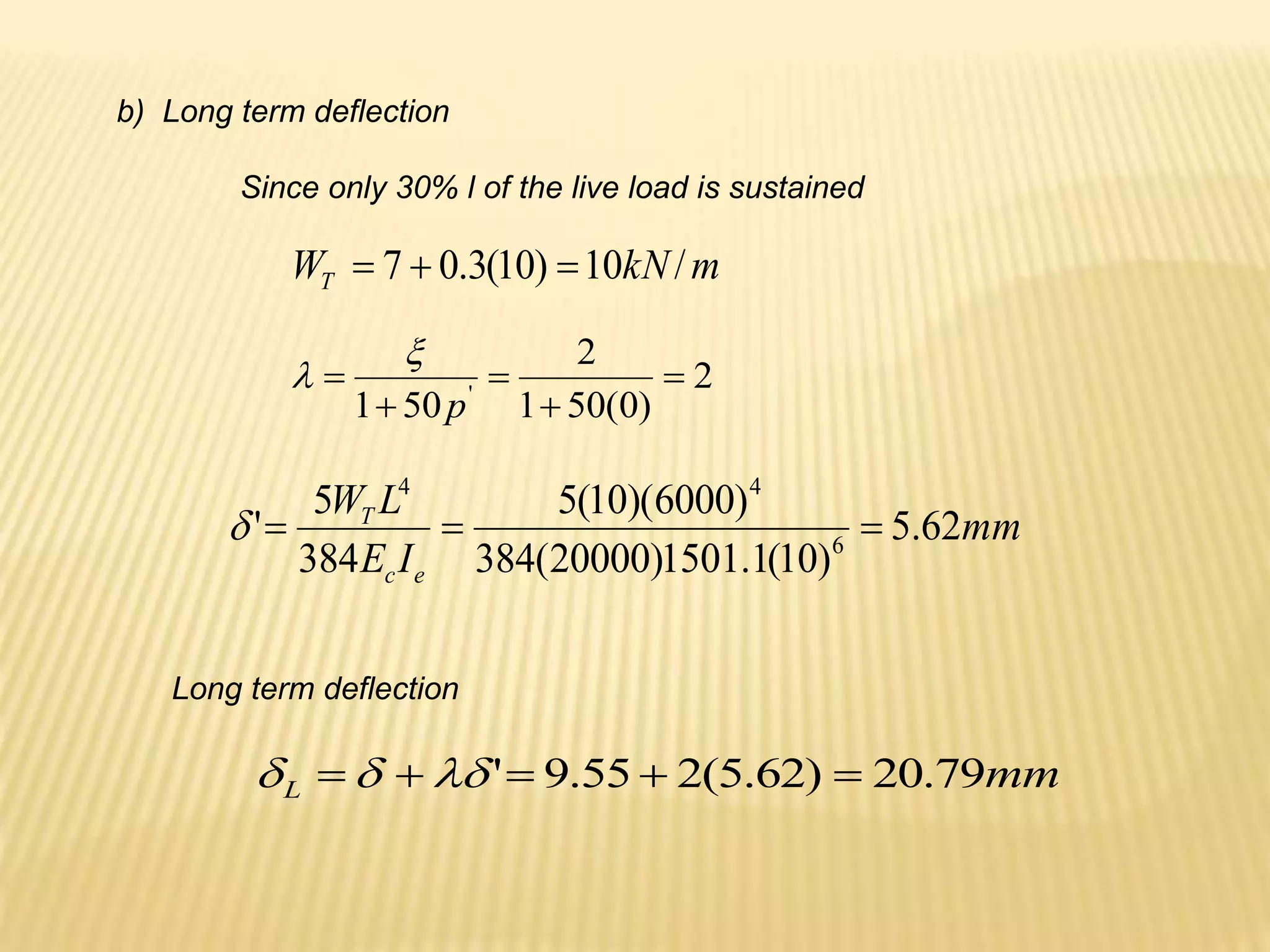
- Flexural design procedures for reinforced concrete beams including assumptions, stress/strain diagrams, and analysis for cases where steel yields or does not yield.
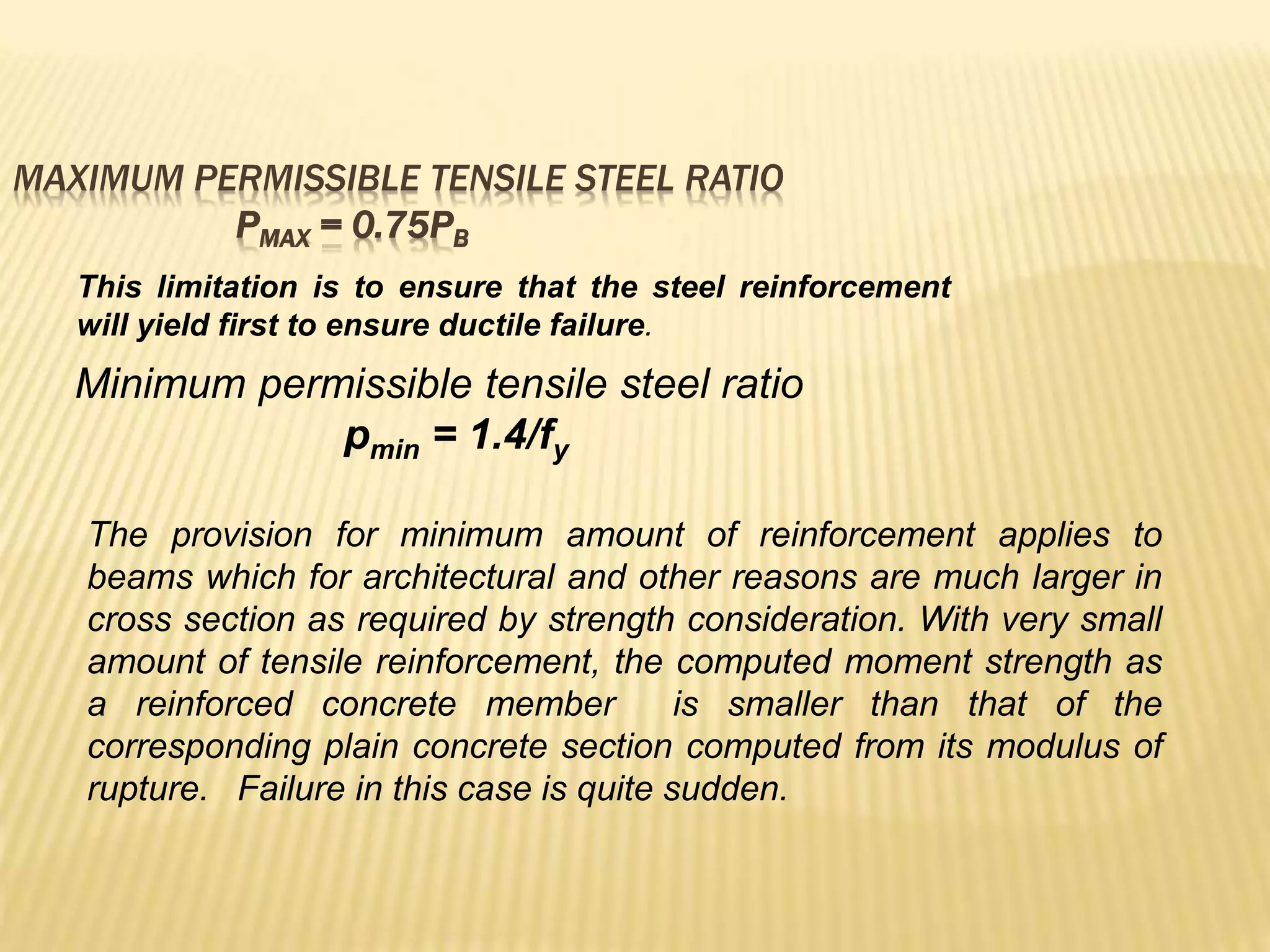
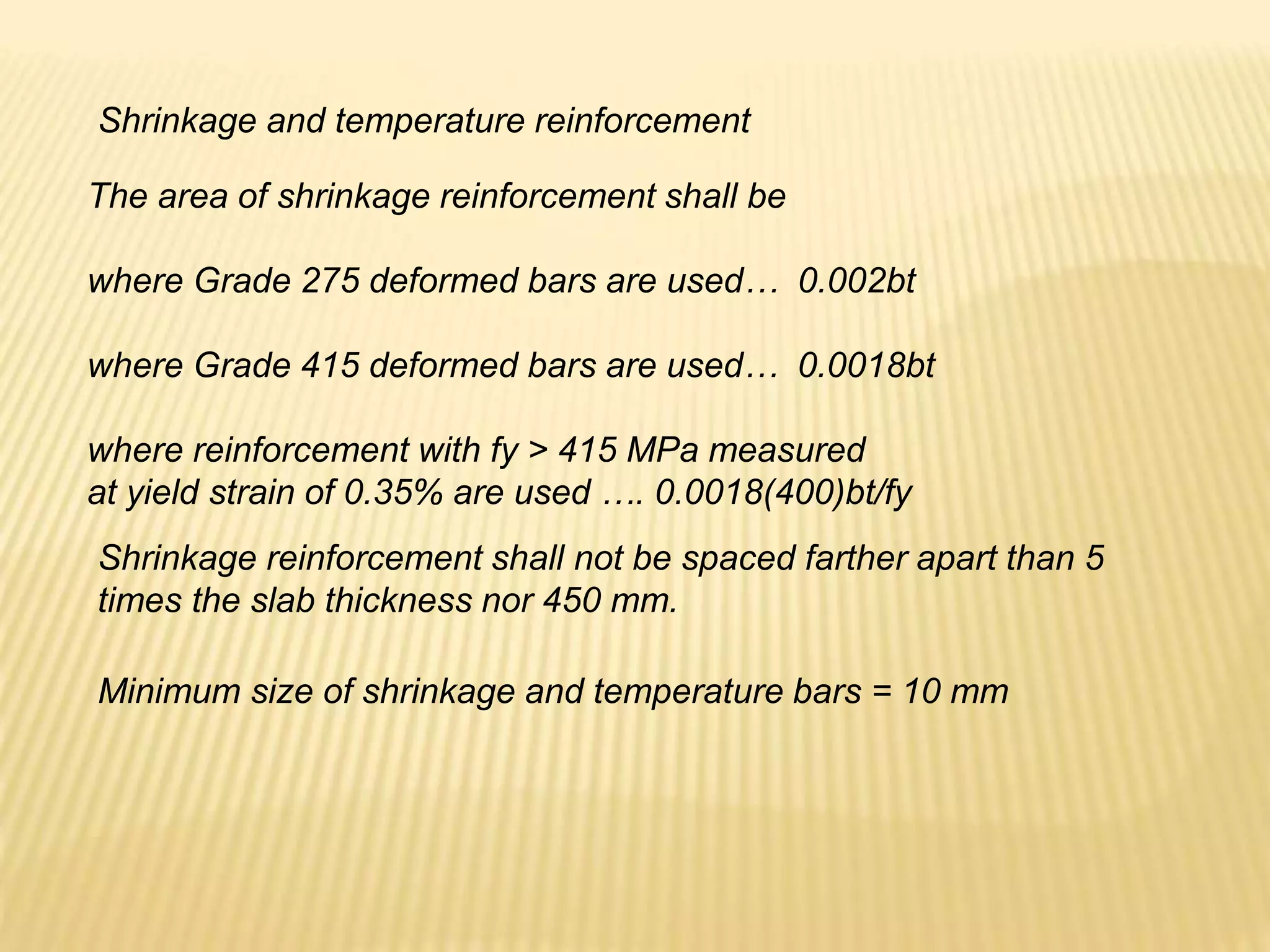
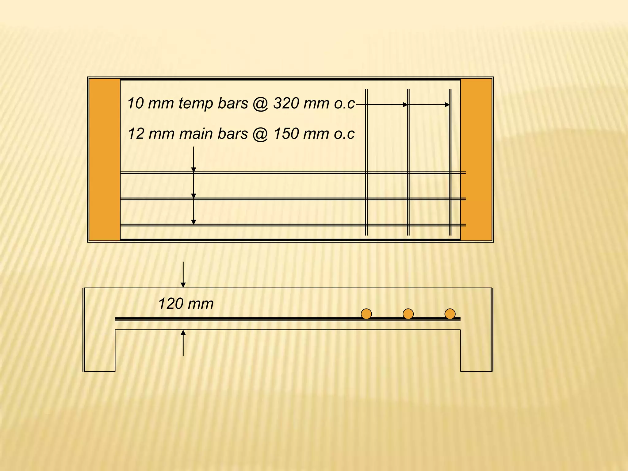
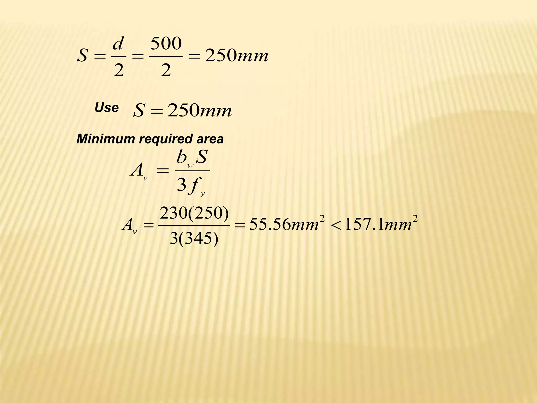
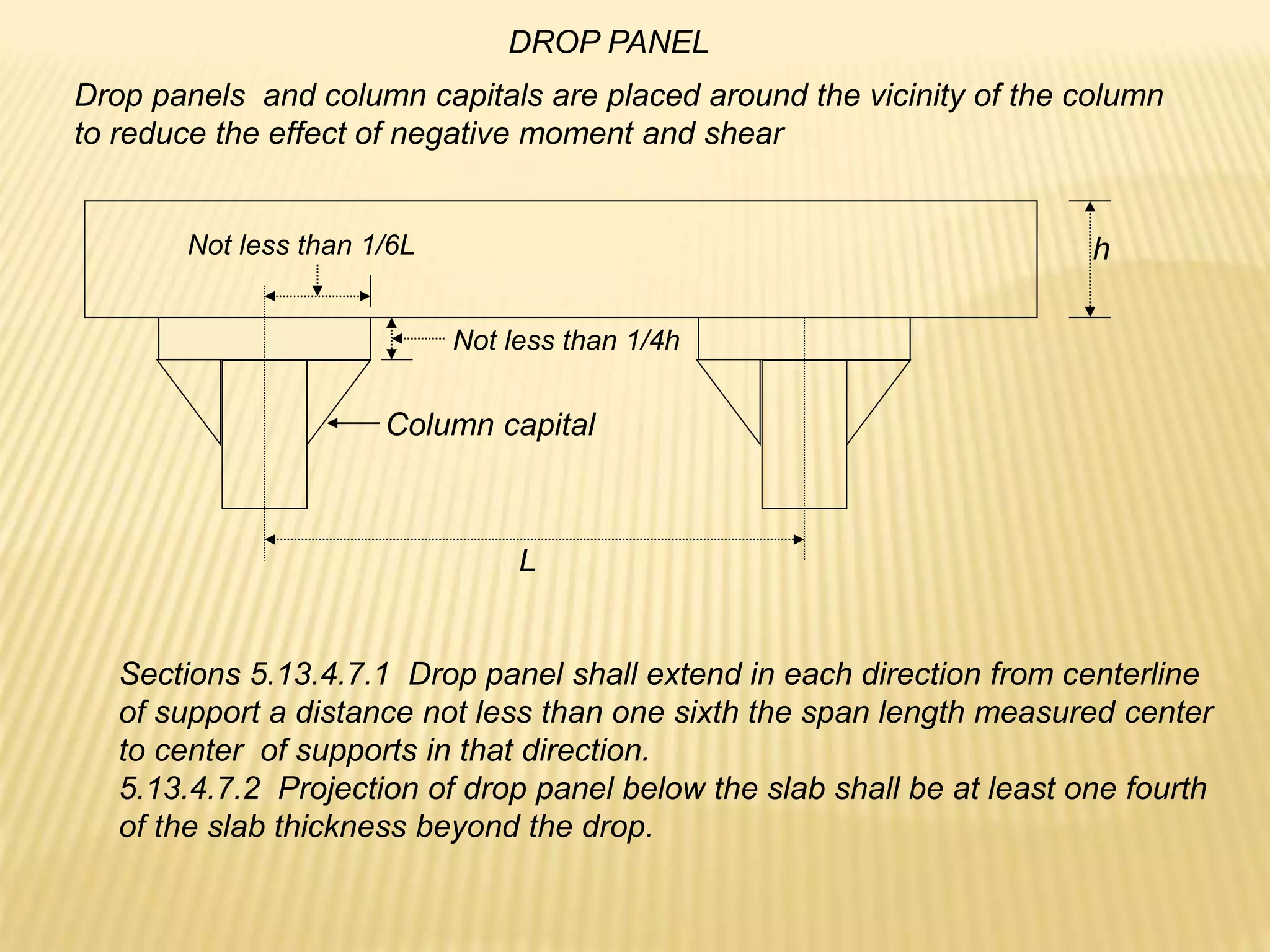
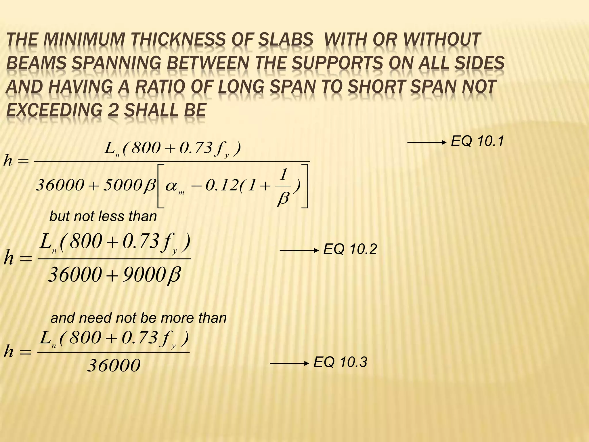
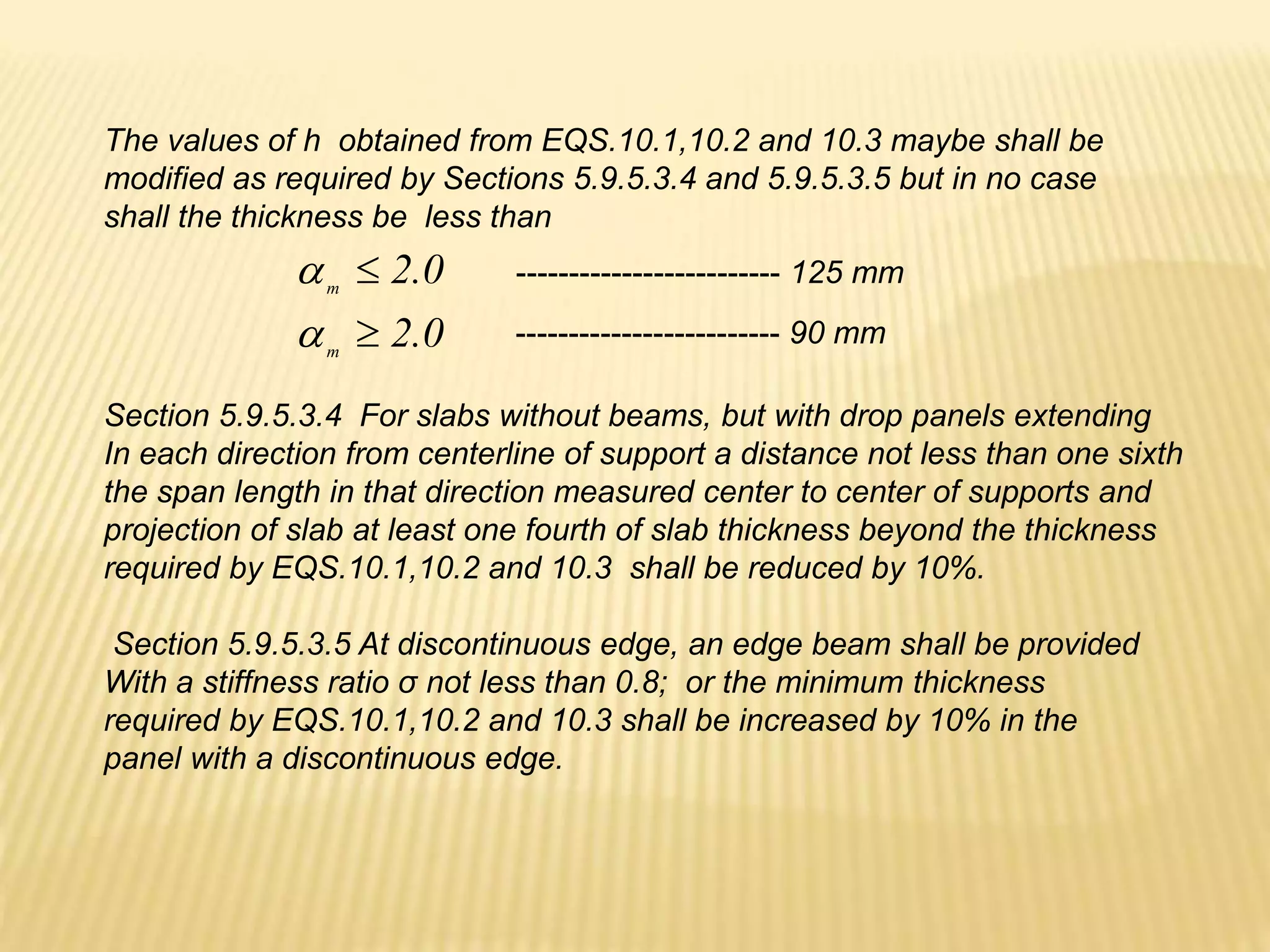
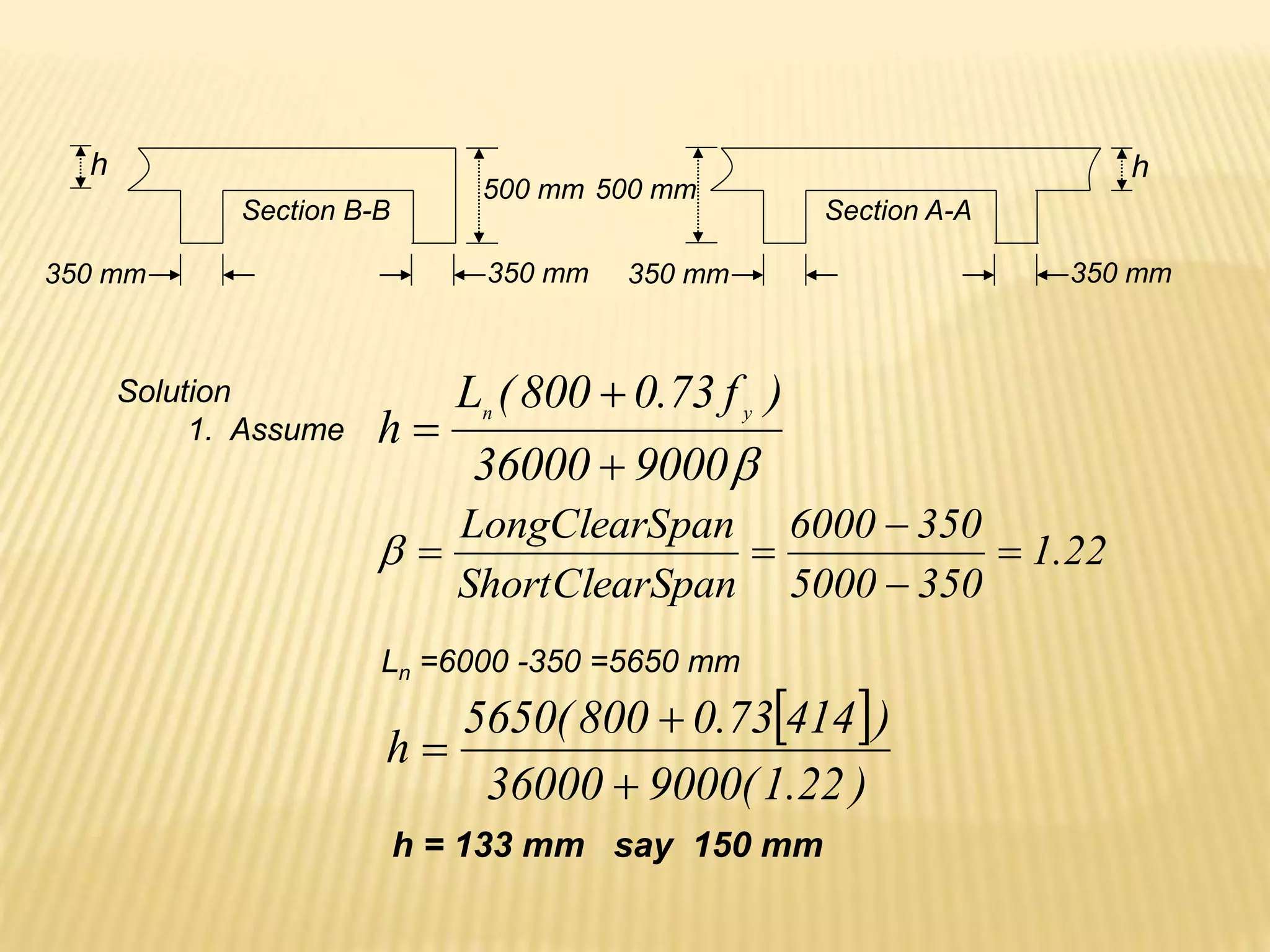
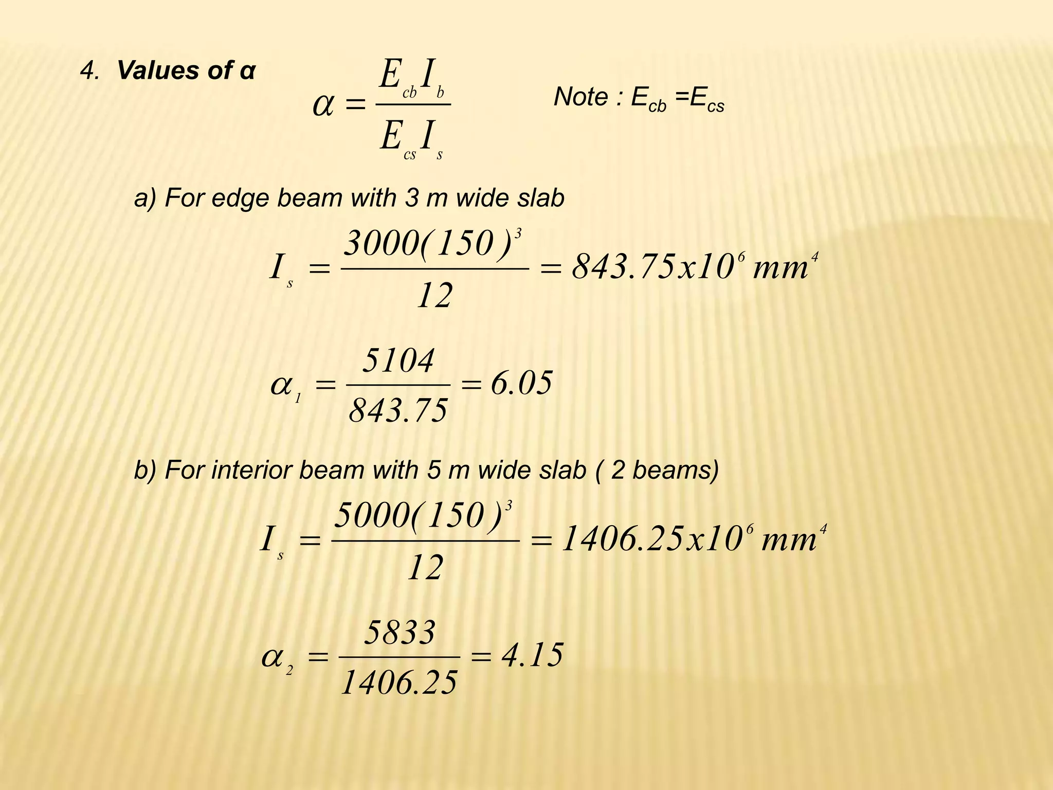
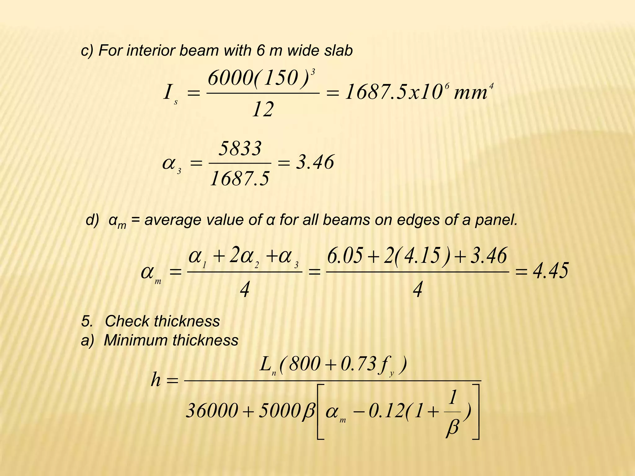
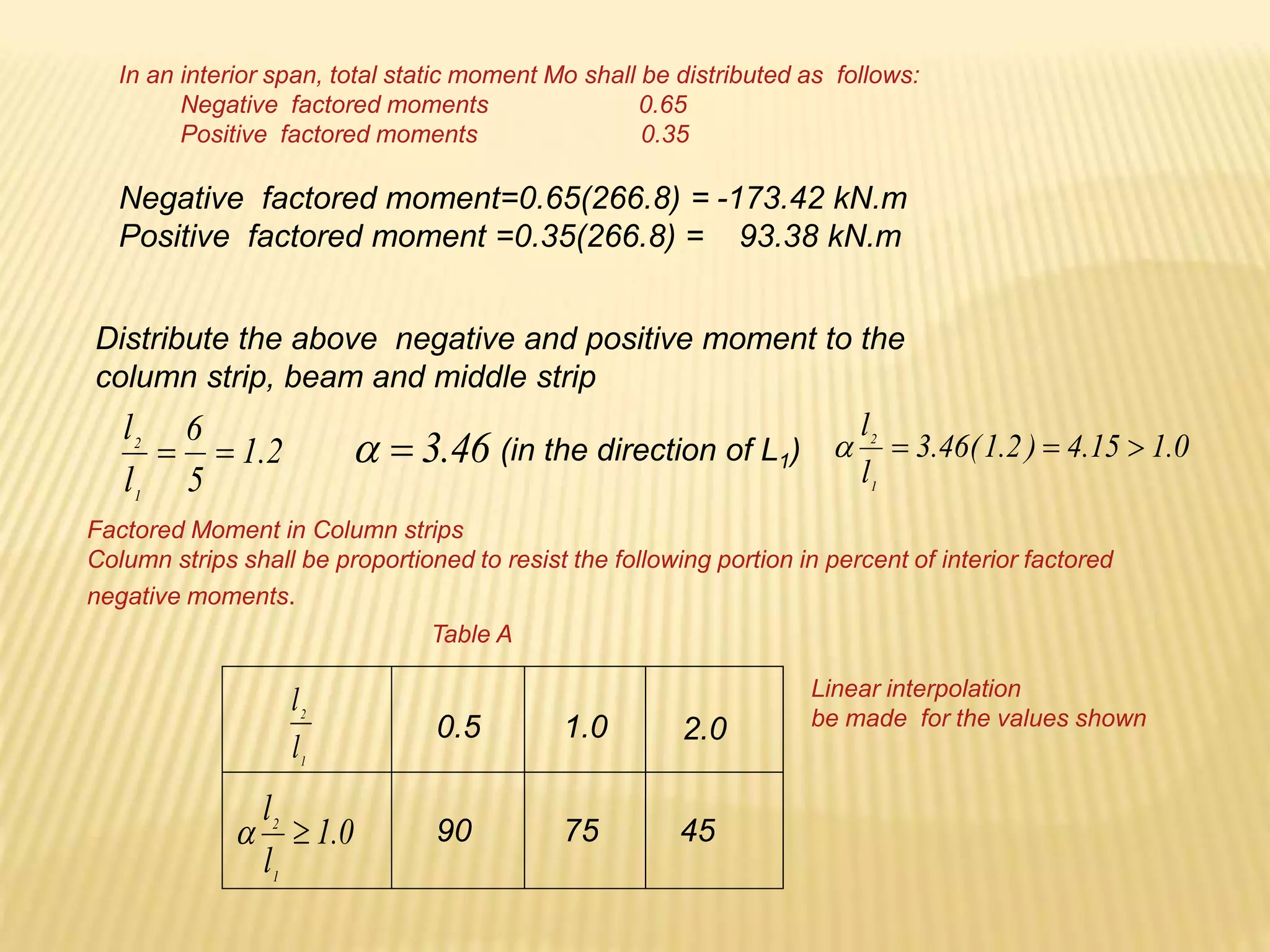
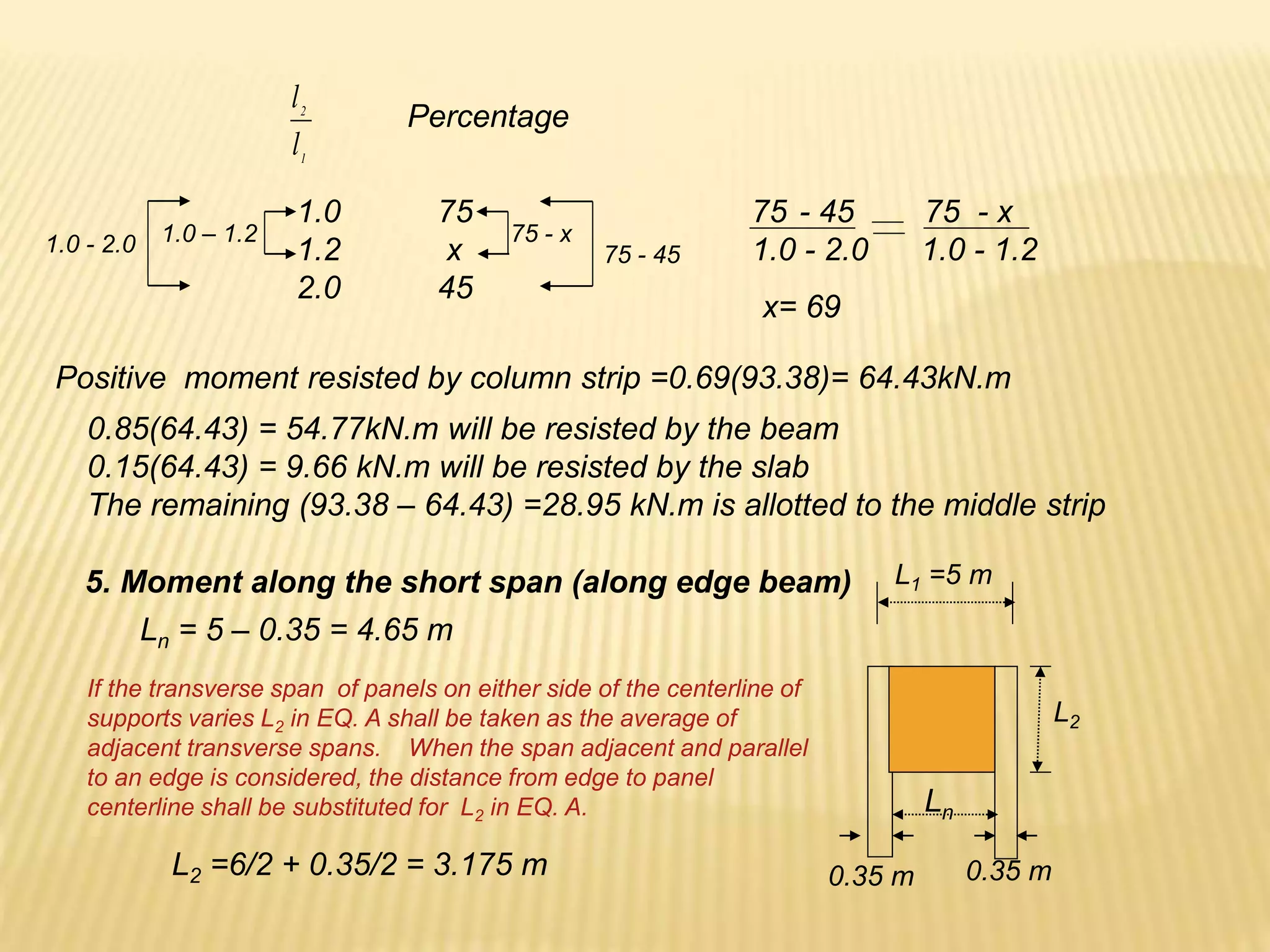
- Requirements for reinforcement spacing, minimum member thicknesses, and ductility.


![c
c
d
s
003
.
0
EQ 2
1
200000
a
c
fs
s
1
1
003
.
0
)
200000
(
a
a
d
fs
600
)
( 1
a
a
d
fs
600
]
)
480
)(
85
.
0
[(
a
a
fs
a
a
fs
600
244800
EQ. 1 = EQ.2
a
a
a
600
244800
56
.
1
a
a 600
244800
56
.
1 2
a
a 6
.
384
923
,
156
2
0
923
,
156
6
.
384
2
a
a](https://image.slidesharecdn.com/reinforcedconcretearki-230107090713-5546eb80/75/reinforced-concrete-arki-ppt-38-2048.jpg)


![mm
b
fc
f
A
a
y
s
1
.
159
350
)
7
.
20
(
85
.
0
)
345
(
2840
'
85
.
0
1
y
s f
MPa
a
d
a
f
67
.
407
1
.
159
)])
60
(
85
.
0
[
1
.
159
(
600
)
(
600 '
1
'
Compression steel yields at failure
m
kN
a
d
f
As
Mu y .
94
.
458
10
)
2
1
.
159
600
)(
345
(
2840
9
.
0
)
2
( 6
1
1
m
kN
d
d
f
As
Mu y .
48
.
206
10
)
60
600
)(
345
(
5
.
1231
9
.
0
)
'
(
' 6
2
m
kN
Mu
Mu
Mu .
42
.
665
48
.
206
94
.
458
2
1
](https://image.slidesharecdn.com/reinforcedconcretearki-230107090713-5546eb80/75/reinforced-concrete-arki-ppt-49-2048.jpg)
![mm
b
fc
f
A
a
y
s
18
.
120
350
)
5
.
27
(
85
.
0
)
345
(
2850
'
85
.
0
1
y
s f
MPa
a
d
a
f
65
.
332
18
.
120
)])
63
(
85
.
0
[
18
.
120
(
600
)
(
600 '
1
'
Compression steel does not yield at failure
Solution to #2
2
1 2850
775
3625
' mm
As
As
As
∑Fx =0 0.85fc’ab + As’fs’ = Asfy
0.85(27.5)350a + 775fs’ = 3625(345)
10.56a +fs’ = 1613.7
fs’ =1613.7 – 10.56 a EQ.1](https://image.slidesharecdn.com/reinforcedconcretearki-230107090713-5546eb80/75/reinforced-concrete-arki-ppt-51-2048.jpg)
![a
a
a
d
a
fs
)])
63
(
85
.
0
[
(
600
)
(
600 '
1
'
2
.
)
55
.
53
(
600
'
EQ
a
a
fs
2
.
1
. EQ
EQ
a
a
a
)
55
.
53
(
600
56
.
10
7
.
1613
32130
600
56
.
10
7
.
1613 2
a
a
a
0
32130
7
.
1013
56
.
10 2
a
a
0
6
.
3042
96
2
a
a
mm
a 12
.
121
2
)
6
.
3042
(
4
)
96
(
96 2
12
.
121
)
55
.
53
12
.
121
(
600
'
s
f
y
s f
MPa
f
7
.
334
'
)
2
(
1
1
a
d
f
As
Mu y
)
'
(
'
'
2 d
d
fs
As
Mu
6
1
10
)
2
12
.
121
600
)(
345
)
2850
(
9
.
0
Mu
m
kN
Mu .
36
.
477
1
6
2
10
)
63
600
(
7
.
334
)
775
(
9
.
0
Mu
m
kN
Mu .
36
.
125
2
m
kN
Mu
Mu
Mu .
72
.
602
2
1
2
'
max 6
.
6500
'
75
.
0 mm
f
fs
A
bd
p
A
y
s
b
s
0365
.
0
345
)
345
600
(
)
600
(
7
.
334
)
5
.
27
(
85
.
0
b
p
yields
TS
3625 2
max mm
As ](https://image.slidesharecdn.com/reinforcedconcretearki-230107090713-5546eb80/75/reinforced-concrete-arki-ppt-52-2048.jpg)


![ax
Ac
2
1
450
375
a
x
1
.
833
.
0 EQ
a
x
)
833
.
0
(
2
1
48
.
11658 a
a
mm
a 3
.
167
mm
a
c 82
.
196
85
.
0
3
.
167
1
From the strain diagram
c
c
s
375
003
.
0
200000
s
s
f
82
.
196
82
.
196
375
003
.
0
)
200000
(
s
f
y
s f
MPa
f
18
.
543 tension steel yields at failure
By similar triangles
m
kN
a
fy
A
M s
u .
34
.
49
10
)
3
3
.
167
]
2
[
375
(
345
)
2
.
603
(
9
.
0
)
3
2
375
( 6
](https://image.slidesharecdn.com/reinforcedconcretearki-230107090713-5546eb80/75/reinforced-concrete-arki-ppt-70-2048.jpg)

![ax
Ac
2
1
475
400
a
x
1
.
842
.
0 EQ
a
x
)
842
.
0
(
2
1
8
.
11829 a
a
mm
a 63
.
167
mm
a
c 21
.
197
85
.
0
63
.
167
1
From the strain diagram
c
c
s
375
003
.
0
200000
s
s
f
21
.
197
21
.
197
400
003
.
0
)
200000
(
s
f
y
s f
MPa
f
98
.
616 tension steel yields at failure
By similar triangles
m
kN
a
fy
A
M sf
u .
98
.
53
10
)
3
63
.
167
]
2
[
400
(
345
)
2
.
603
(
9
.
0
)
3
2
400
( 6
](https://image.slidesharecdn.com/reinforcedconcretearki-230107090713-5546eb80/75/reinforced-concrete-arki-ppt-73-2048.jpg)


![)
]
'
85
.
0
[
2
(
b
fc
f
A
d
f
A
M
y
s
y
s
u
EQ.2 in EQ.1
)
]
'
85
.
0
[
2
(
d
b
fc
d
f
A
d
bd
bd
f
A
M
y
s
y
s
u
)
]
'
85
.
0
[(
2
( d
fc
f
bd
A
d
bdf
bd
A
M
y
s
y
s
u
bd
A
p s
'
85
.
0 fc
f
m
y
Let and](https://image.slidesharecdn.com/reinforcedconcretearki-230107090713-5546eb80/75/reinforced-concrete-arki-ppt-83-2048.jpg)
![2
2
4
)
2
(
2
2
2
y
u
f
m
mR
m
m
p
2
]
2
1
[
)
2
(
2 2
y
u
f
mR
m
m
p
2
2
1
2
2
y
u
f
mR
m
m
p
2
]
2
1
1
[
2
y
u
f
mR
m
p
)
2
1
1
(
1
y
u
f
mR
m
p
Actual tensile steel ratio](https://image.slidesharecdn.com/reinforcedconcretearki-230107090713-5546eb80/75/reinforced-concrete-arki-ppt-86-2048.jpg)


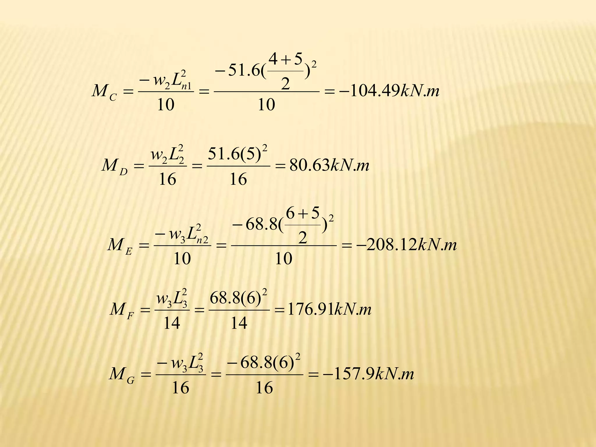
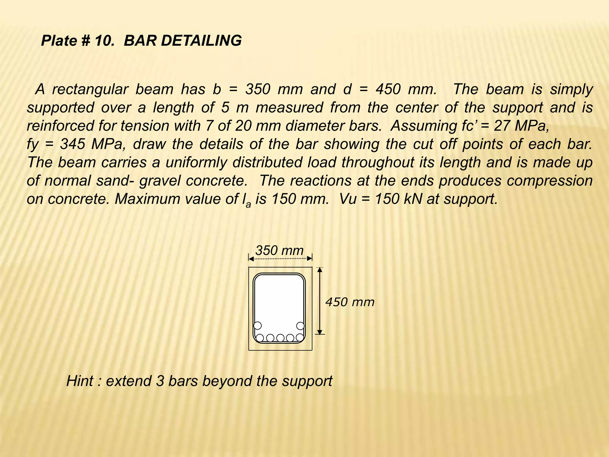
![Problems :
Design a rectangular beam for a 6 m simple span to support a uniform
dead load of 15 kN/m and uniform live load of 24 kN/m applied along it’s
entire length. fc’=20 MPa, fy = 350 MPa,Wc=23.5 kN/m3
25
.
3
]
2
)
59
.
20
(
0104
.
0
1
)[
350
(
0104
.
0
)
2
1
(
59
.
20
)
20
(
85
.
0
350
'
85
.
0
0104
.
0
350
)
350
600
(
)
600
(
85
.
0
)
20
(
85
.
0
4
.
0
4
.
0
.
4
.
327
8
)
6
(
24
7
.
1
8
)
6
(
8
.
22
4
.
1
/
8
.
22
8
.
7
15
8
.
7
)
15
24
(
20
.
0
2
2
pm
pf
R
fc
fy
m
p
p
m
kN
M
m
kN
W
w
y
u
b
u
D
B](https://image.slidesharecdn.com/reinforcedconcretearki-230107090713-5546eb80/75/reinforced-concrete-arki-ppt-95-2048.jpg)


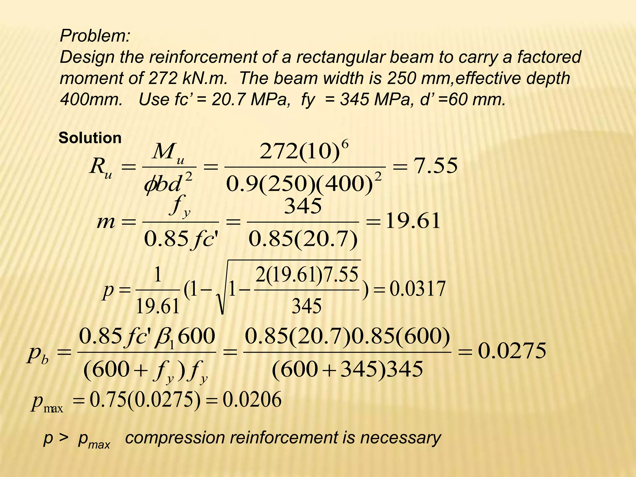
![2
max
1 2060
400
)
250
(
0206
.
0 mm
bd
p
As
mm
b
fc
f
A
a
y
s
57
.
161
250
)
7
.
20
(
85
.
0
)
345
(
2060
'
85
.
0
1
m
kN
a
d
f
A
M y
s
u .
18
.
204
10
)
2
57
.
161
400
(
345
)
2060
(
9
.
0
)
2
( 6
1
1
m
kN
M
M
M u
u
u .
82
.
67
18
.
204
272
1
2
2
6
2
2 42
.
642
)
60
400
)(
345
(
9
.
0
)
10
(
82
.
67
)
'
(
mm
d
d
f
M
A
y
u
s
MPa
a
d
a
fs 6
.
410
57
.
161
)])
60
(
85
.
0
[
57
.
161
(
600
)
(
600 '
1
'
Compression
Steel yields
at failure
2
2
'
42
.
642 mm
A
A s
s
2
2
1 42
.
2702
42
.
642
2060 mm
A
A
A s
s
s
](https://image.slidesharecdn.com/reinforcedconcretearki-230107090713-5546eb80/75/reinforced-concrete-arki-ppt-119-2048.jpg)


![mm
b
fc
f
A
a
y
s
18
.
120
350
)
5
.
27
(
85
.
0
)
345
(
2850
'
85
.
0
1
y
s f
MPa
a
d
a
f
65
.
332
18
.
120
)])
63
(
85
.
0
[
18
.
120
(
600
)
(
600 '
1
'
Compression steel does not yields at failure
2
1 2850
775
3625
' mm
As
As
As
∑Fx =0 0.85fc’ab + As’fs’ = Asfy
0.85(27.5)350a + 775fs’ = 3625(345)
10.56a +fs’ = 1613.7
fs’ =1613.7 – 10.56 a EQ.1
Solution to #2](https://image.slidesharecdn.com/reinforcedconcretearki-230107090713-5546eb80/75/reinforced-concrete-arki-ppt-146-2048.jpg)
![a
a
a
d
a
fs
)])
63
(
85
.
0
[
(
600
)
(
600 '
1
'
2
.
)
55
.
53
(
600
'
EQ
a
a
fs
2
.
1
. EQ
EQ
a
a
a
)
55
.
53
(
600
56
.
10
7
.
1613
32130
600
56
.
10
7
.
1613 2
a
a
a
0
32130
7
.
1013
56
.
10 2
a
a
0
6
.
3042
96
2
a
a
mm
a 12
.
121
2
)
6
.
3042
(
4
)
96
(
96 2
12
.
121
)
55
.
53
12
.
121
(
600
'
s
f
y
s f
MPa
f
7
.
334
'
)
2
(
1
1
a
d
f
As
Mu y
)
'
(
'
'
2 d
d
fs
As
Mu
6
1
10
)
2
12
.
121
600
)(
345
)
2850
(
9
.
0
Mu
m
kN
Mu .
36
.
477
1
6
2
10
)
63
600
(
7
.
334
)
775
(
9
.
0
Mu
m
kN
Mu .
36
.
125
2
m
kN
Mu
Mu
Mu .
72
.
602
2
1
2
'
max 6
.
6500
'
75
.
0 mm
f
fs
A
bd
p
A
y
s
b
s
0365
.
0
345
)
345
600
(
)
600
(
7
.
334
)
5
.
27
(
85
.
0
b
p](https://image.slidesharecdn.com/reinforcedconcretearki-230107090713-5546eb80/75/reinforced-concrete-arki-ppt-147-2048.jpg)


![ax
Ac
2
1
475
400
a
x
1
.
842
.
0 EQ
a
x
)
842
.
0
(
2
1
45
.
11827 a
a
mm
a 6
.
167
mm
a
c 17
.
197
85
.
0
6
.
167
1
From the strain diagram
c
c
s
400
003
.
0
2000000
s
s
f
17
.
197
17
.
197
400
003
.
0
)
200000
(
s
f
y
s f
MPa
f
22
.
617 tension steel yields at failure
By similar triangles
m
kN
a
f
A
M y
s
u .
91
.
53
10
)
3
6
.
167
]
2
[
400
(
345
)
2
.
603
(
9
.
0
)
3
2
375
( 6
](https://image.slidesharecdn.com/reinforcedconcretearki-230107090713-5546eb80/75/reinforced-concrete-arki-ppt-150-2048.jpg)


![29
.
20
)
20
(
85
.
0
345
'
85
.
0
fc
f
m
y
Solution
m
kN
Wu /
6
.
45
)
12
(
7
.
1
)
18
(
4
.
1
m
kN
L
W
M u
u .
2
.
205
8
)
6
(
6
.
45
8
2
2
02659
.
0
345
)
345
600
(
)
600
(
85
.
0
)
20
(
85
.
0
)
600
(
600
'
85
.
0 1
y
y
b
f
f
fc
p
012
.
0
02659
.
0
)
75
.
0
(
6
.
0
)
75
.
0
)(
6
.
0
(
b
p
p
MPa
pm
pf
R y
u 635
.
3
)
2
]
29
.
20
[
012
.
0
1
)(
345
(
012
.
0
)
2
1
(
](https://image.slidesharecdn.com/reinforcedconcretearki-230107090713-5546eb80/75/reinforced-concrete-arki-ppt-168-2048.jpg)


![PROBLEMS
A square tied column 350 mm by 350 mm is reinforced with 6 of 25
mm bars with fc’ = 20.7 MPa and fy = 345 MPa. Determine the
following :
a) Ultimate axial load capacity of the column.
b) spacing of 10 mm lateral ties
Solution
Pu =Ф0.80{0.85fc’(Ag-Ast) + Astfy} 2
2
25
.
2945
4
)
25
(
6 mm
Ast
kN
1747
1000
)}
345
(
25
.
2945
]
25
.
2945
)
350
)(
350
)[(
7
.
20
(
85
.
0
){
80
.
0
(
7
.
0
Pu
mm
S 400
)
25
(
16
mm
S 480
)
10
(
48
mm
S 350
Use S = 350 mm
Spacing of 10 mm ties](https://image.slidesharecdn.com/reinforcedconcretearki-230107090713-5546eb80/75/reinforced-concrete-arki-ppt-218-2048.jpg)
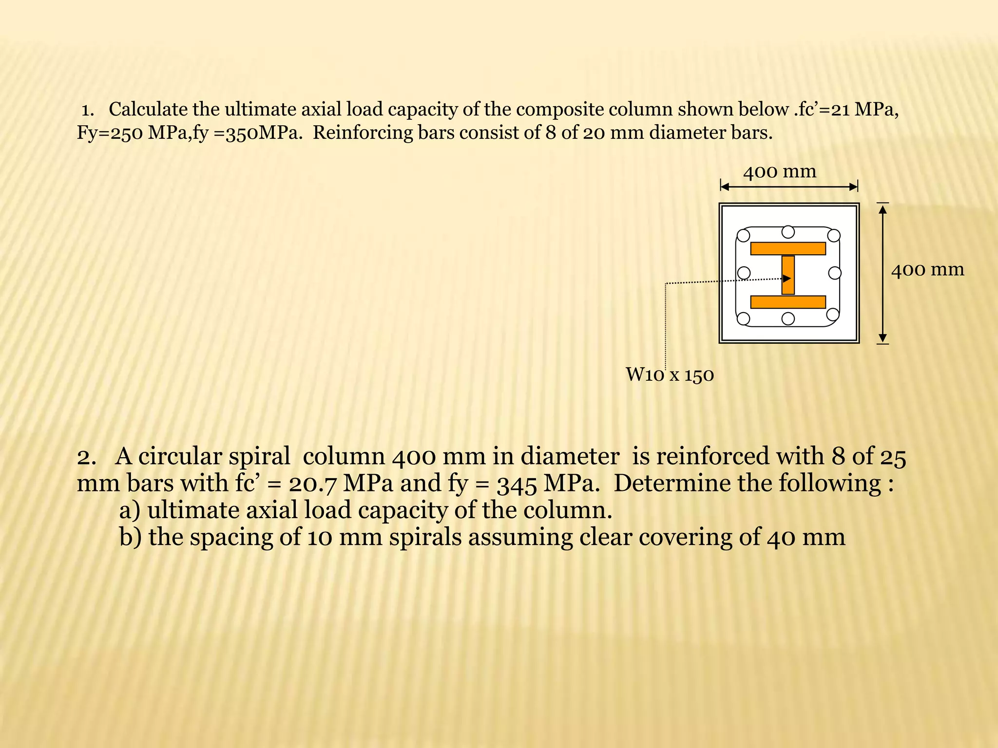
![PROBLEMS
A circular spiral column 400 mm in diameter is reinforced with 8 of
25 mm bars with fc’ = 20.7 MPa and fy = 345 MPa. Determine the
following :
a) ultimate axial load capacity of the column.
b) the spacing of 10 mm spirals assuming clear covering of 40 mm
Solution
Pu =Ф0.85{0.85fc’(Ag-Ast) + Astfy}
2
2
3927
4
)
25
(
8 mm
Ast
kN
2
.
2229
1000
)}
345
(
3927
]
3927
125664
)[(
7
.
20
(
85
.
0
){
85
.
0
(
75
.
0
Pu
2
2
125664
4
)
400
(
mm
Ag
](https://image.slidesharecdn.com/reinforcedconcretearki-230107090713-5546eb80/75/reinforced-concrete-arki-ppt-219-2048.jpg)


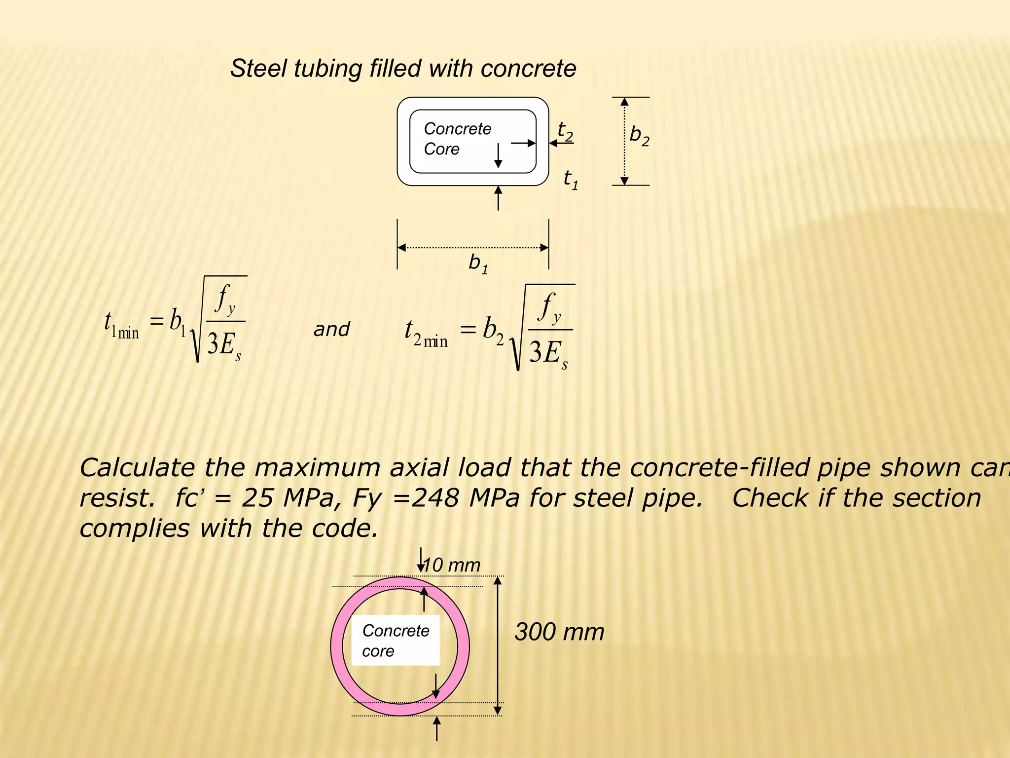
![
y
p
c
u F
A
A
fc
P
'
85
.
0
85
.
0
2
2
2
9111
4
]
)
280
(
)
300
[(
mm
Ap
2
2
61575
4
]
)
280
[(
mm
Ac
N
Pu 2122958
)
248
(
9111
)
61575
)(
25
(
85
.
0
85
.
0
)
7
.
0
(
mm
mm
E
f
D
t
s
y
10
74
.
3
)
200000
(
8
248
300
8
min
Minimum required thickness of pipe](https://image.slidesharecdn.com/reinforcedconcretearki-230107090713-5546eb80/75/reinforced-concrete-arki-ppt-224-2048.jpg)

![W14 x 210
Calculate the ultimate axial load capacity of the composite column shown
below .fc’=21 MPa, Fy=248 MPa,fy =276MPa.
Reinforcing bars consist of 8 of 20 mm diameter bars.
Properties of W 14 x 210
Area = 40000 mm2
Depth = 400 mm
500 mm
500 mm
y
WF
y
s
c
u F
A
f
A
A
fc
P
'
85
.
0
85
.
0
2
2
2513
4
]
)
20
[(
8
mm
As
)
248
(
40000
)
276
(
2513
)
207487
)(
21
(
85
.
0
85
.
0
)
7
.
0
(
u
P
2
207487
2513
40000
)
500
(
500 mm
Ac
N
Pu 8518752
](https://image.slidesharecdn.com/reinforcedconcretearki-230107090713-5546eb80/75/reinforced-concrete-arki-ppt-226-2048.jpg)


![]
7
.
1
7
.
1
4
.
1
[
75
.
0
2 W
L
D
s M
M
M
M
m
kN
M s .
5
.
127
)]
100
(
7
.
1
)
0
(
7
.
1
)
0
(
4
.
1
[
75
.
0
2
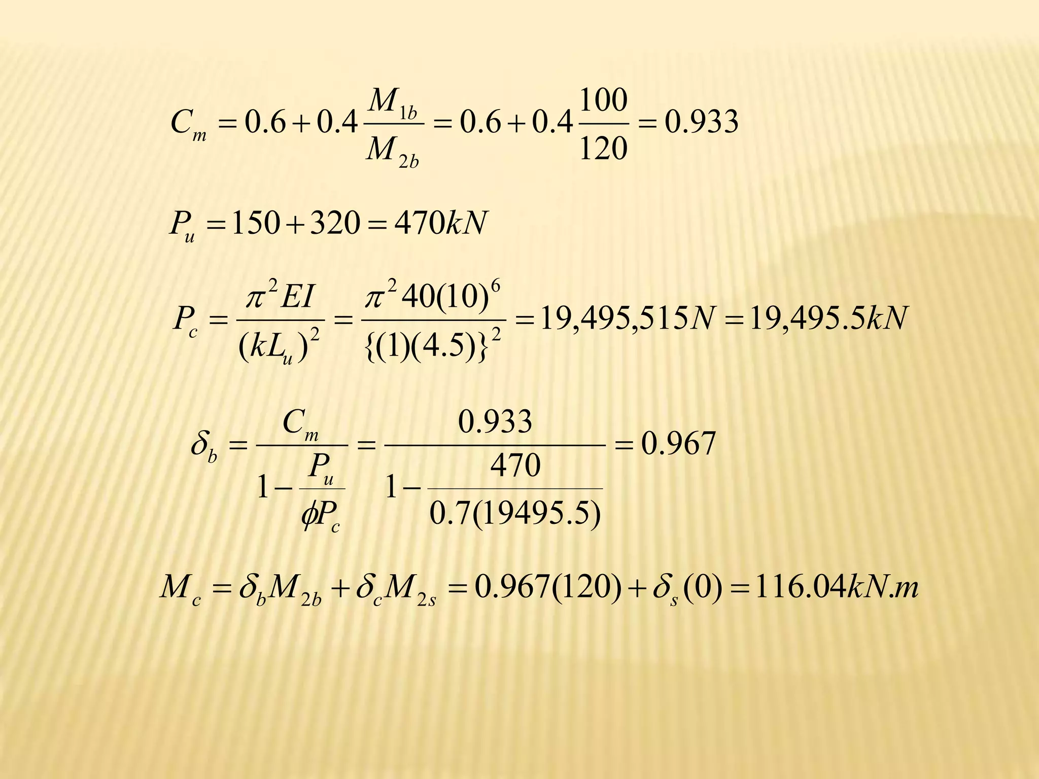
Solution to #2
kN
P
P L
D 500
350
150
]
7
.
1
4
.
1
[
Specified in the previous
problem
kN
P
P
P
P W
L
D
u 7
.
540
)]
130
(
7
.
1
500
[
75
.
0
]
7
.
1
7
.
1
4
.
1
[
75
.
0
014
.
1
)
18
.
16571
(
7
.
0
75
.
540
1
9668
.
0
1
c
u
m
b
P
P
C
m
kN
M
M
M s
s
b
b
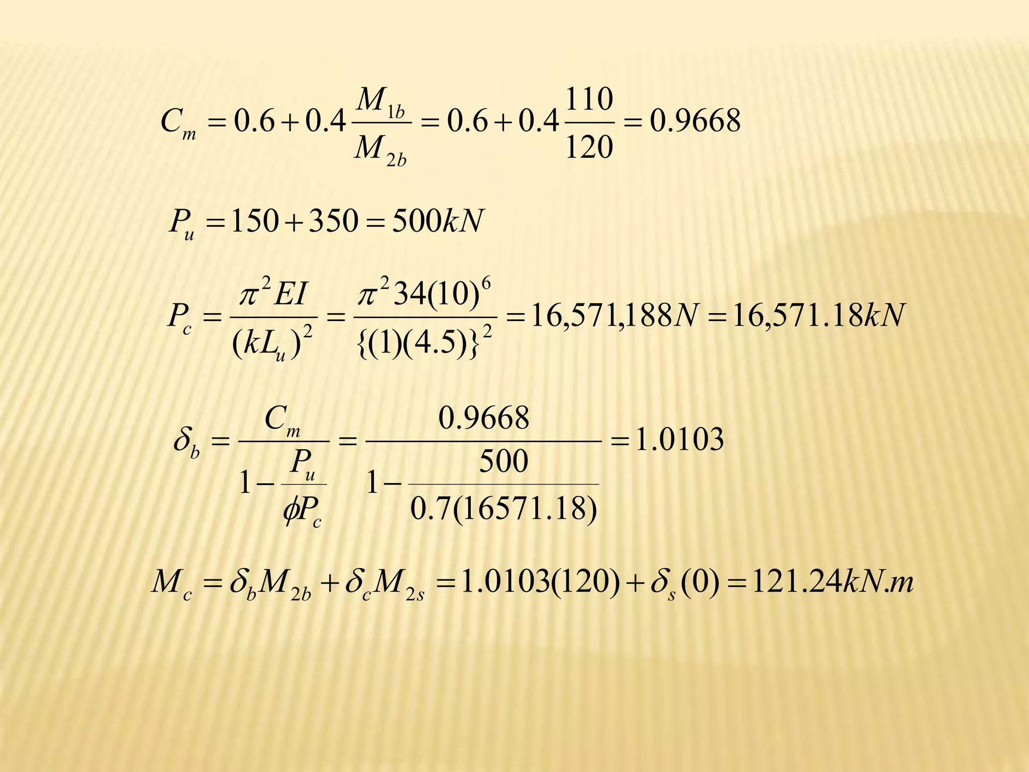
c .
18
.
249
)
5
.
127
(
0
.
1
)
120
(
014
.
1
2
2
0
.
1
s
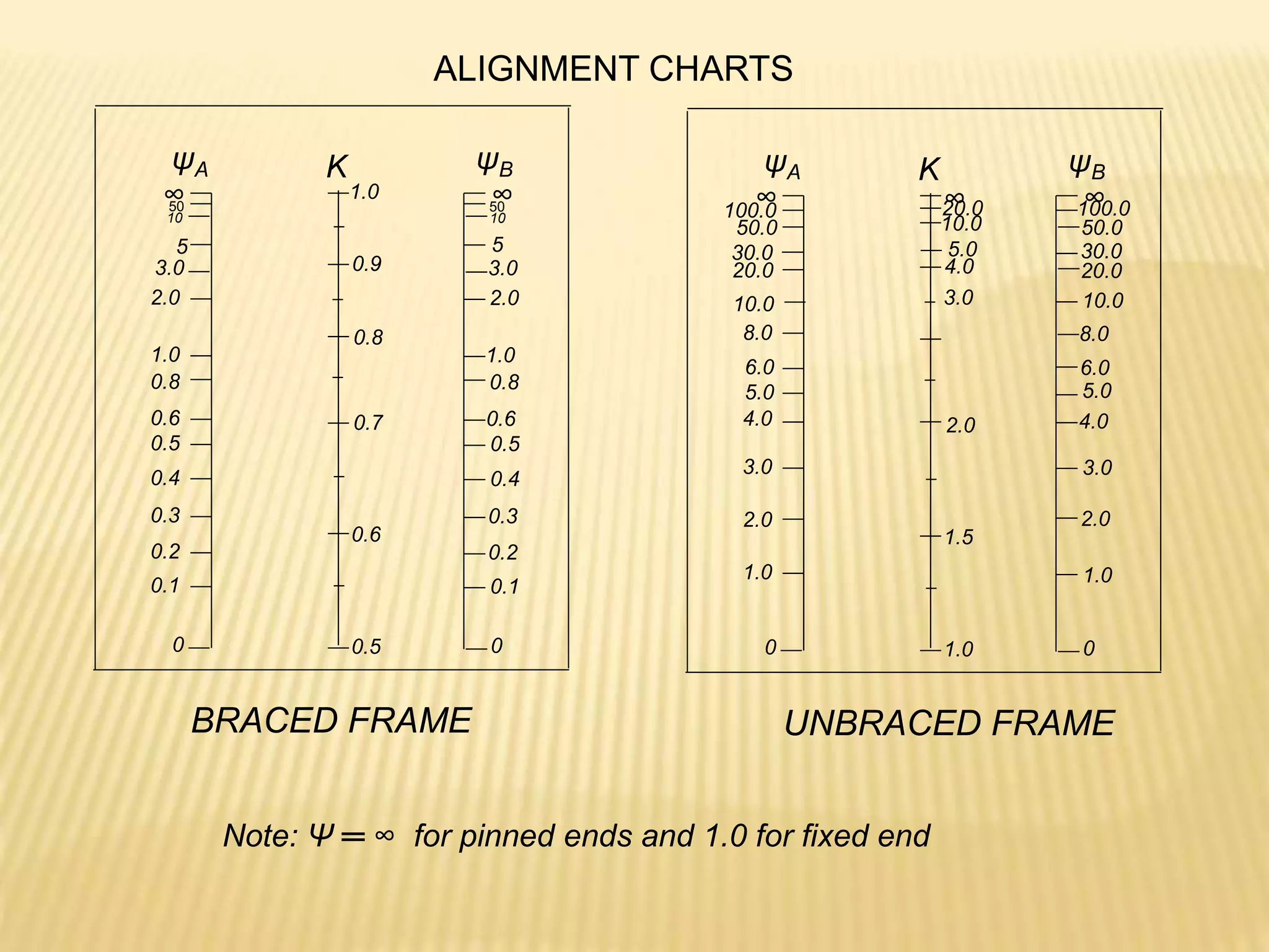
Frame is braced against sidesway](https://image.slidesharecdn.com/reinforcedconcretearki-230107090713-5546eb80/75/reinforced-concrete-arki-ppt-310-2048.jpg)


![Design of As
004
.
0
350
4
.
1
4
.
1
59
.
20
)
20
(
85
.
0
350
'
85
.
0
min
fy
p
fc
fy
m
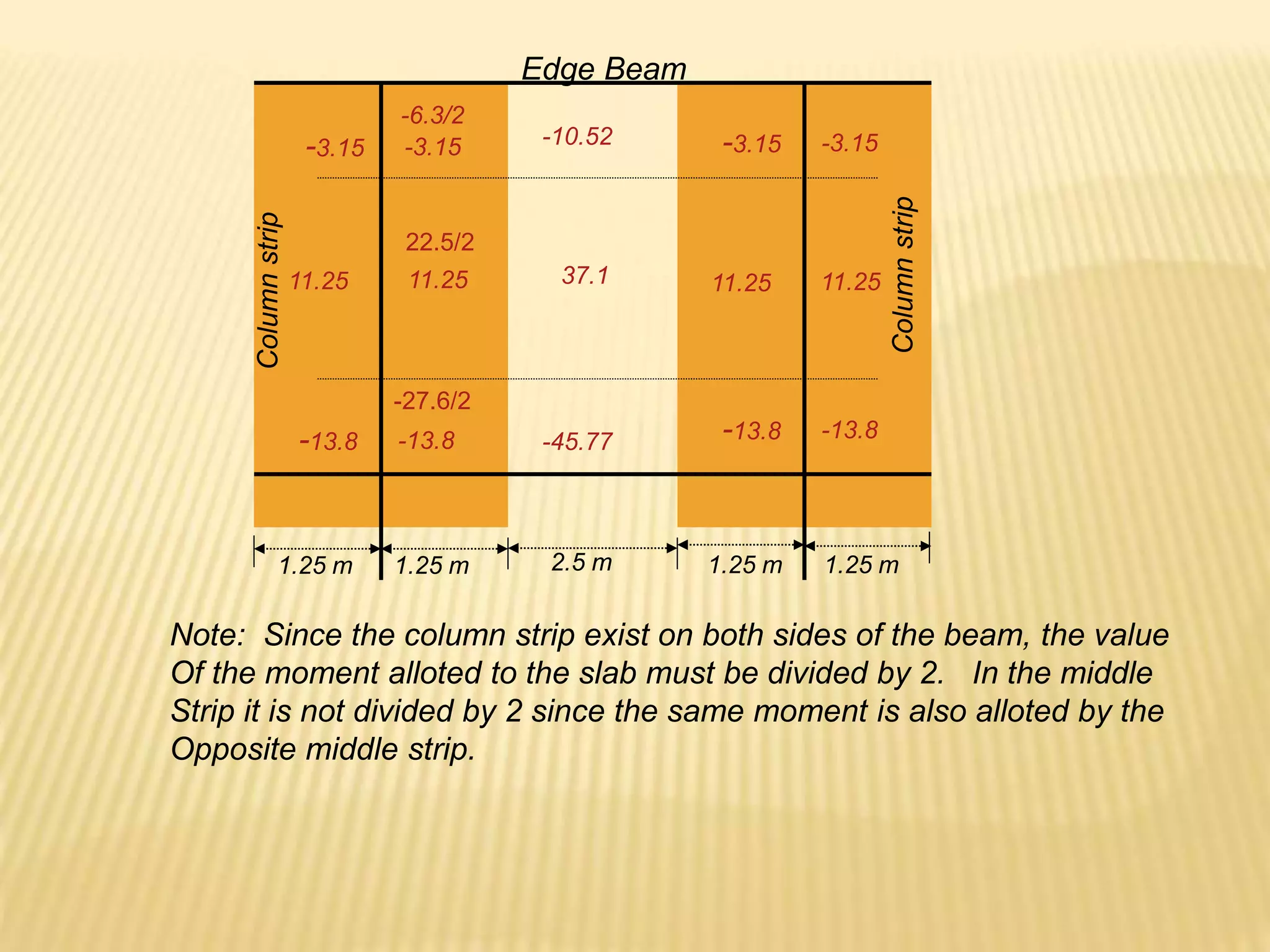
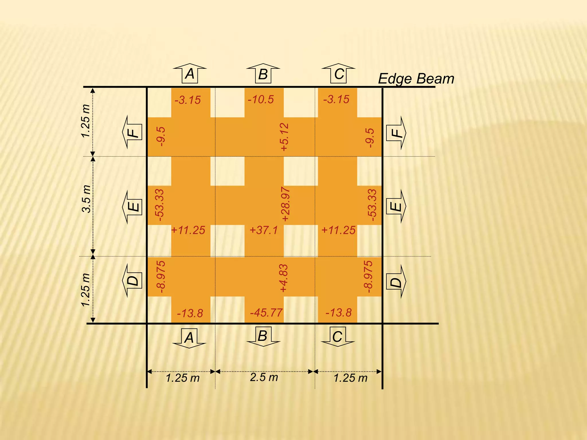
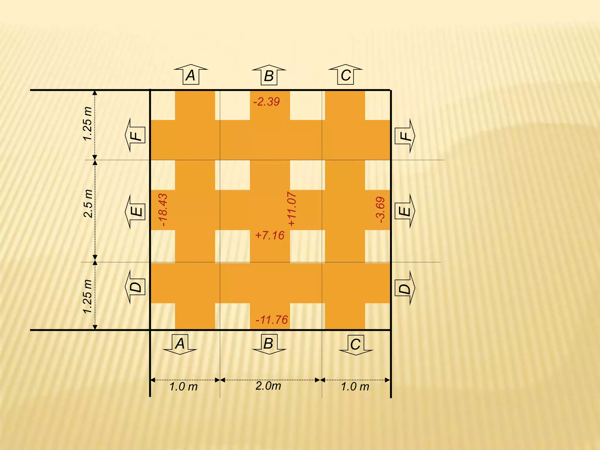
Short Direction
Negative reinforcement at continuous edge Mu=18.43 kN.m
]
2
1
1
[
1
74
.
3
)
74
)(
1000
(
9
.
0
)
10
(
43
.
18
2
6
2
fy
mR
m
p
bd
M
R
u
u
u
012
.
0
]
350
74
.
3
)
59
.
20
(
2
1
1
[
59
.
20
1
p
2
888
74
)
1000
(
012
.
0 mm
pbd
As
s
A
A
S 1
1000
mm
120
say
128
888
1
.
113
1000
1
.
113
4
)
12
(
bars
mm
12
Using
2
2
1
mm
S
S
mm
A
](https://image.slidesharecdn.com/reinforcedconcretearki-230107090713-5546eb80/75/reinforced-concrete-arki-ppt-378-2048.jpg)
![Positive reinforcement at midspan Mu=11.07 kN.m
25
.
2
)
74
)(
1000
(
9
.
0
)
10
(
07
.
11
2
6
2
bd
M
R u
u
00692
.
0
]
350
25
.
2
)
59
.
20
(
2
1
1
[
59
.
20
1
p
2
08
.
512
74
)
1000
(
00692
.
0 mm
pbd
As
s
A
A
S 1
1000
mm
220
say
86
.
220
512
1
.
113
1000
1
.
113
4
)
12
( 2
2
1
S
S
mm
A ](https://image.slidesharecdn.com/reinforcedconcretearki-230107090713-5546eb80/75/reinforced-concrete-arki-ppt-379-2048.jpg)
![Long Direction
Negative reinforcement at continuous edge Mu=11.76 kN.m
]
2
1
1
[
1
39
.
2
)
74
)(
1000
(
9
.
0
)
10
(
76
.
11
2
6
2
fy
mR
m
p
bd
M
R
u
u
u
0074
.
0
]
350
39
.
2
)
59
.
20
(
2
1
1
[
59
.
20
1
p
2
548
74
)
1000
(
0074
.
0 mm
pbd
As
s
A
A
S 1
1000
mm
200
say
39
.
206
548
1
.
113
1000
1
.
113
4
)
12
(
bars
mm
12
Using
2
2
1
mm
S
S
mm
A
](https://image.slidesharecdn.com/reinforcedconcretearki-230107090713-5546eb80/75/reinforced-concrete-arki-ppt-380-2048.jpg)
![Positive reinforcement at midspan Mu=7.16 kN.m
45
.
1
)
74
)(
1000
(
9
.
0
)
10
(
16
.
7
2
6
2
bd
M
R u
u
0043
.
0
]
350
45
.
1
)
59
.
20
(
2
1
1
[
59
.
20
1
p
2
2
.
318
74
)
1000
(
0043
.
0 mm
pbd
As
s
A
A
S 1
1000
mm
300
say
4
.
355
2
.
318
1
.
113
1000
1
.
113
4
)
12
( 2
2
1
S
S
mm
A ](https://image.slidesharecdn.com/reinforcedconcretearki-230107090713-5546eb80/75/reinforced-concrete-arki-ppt-381-2048.jpg)

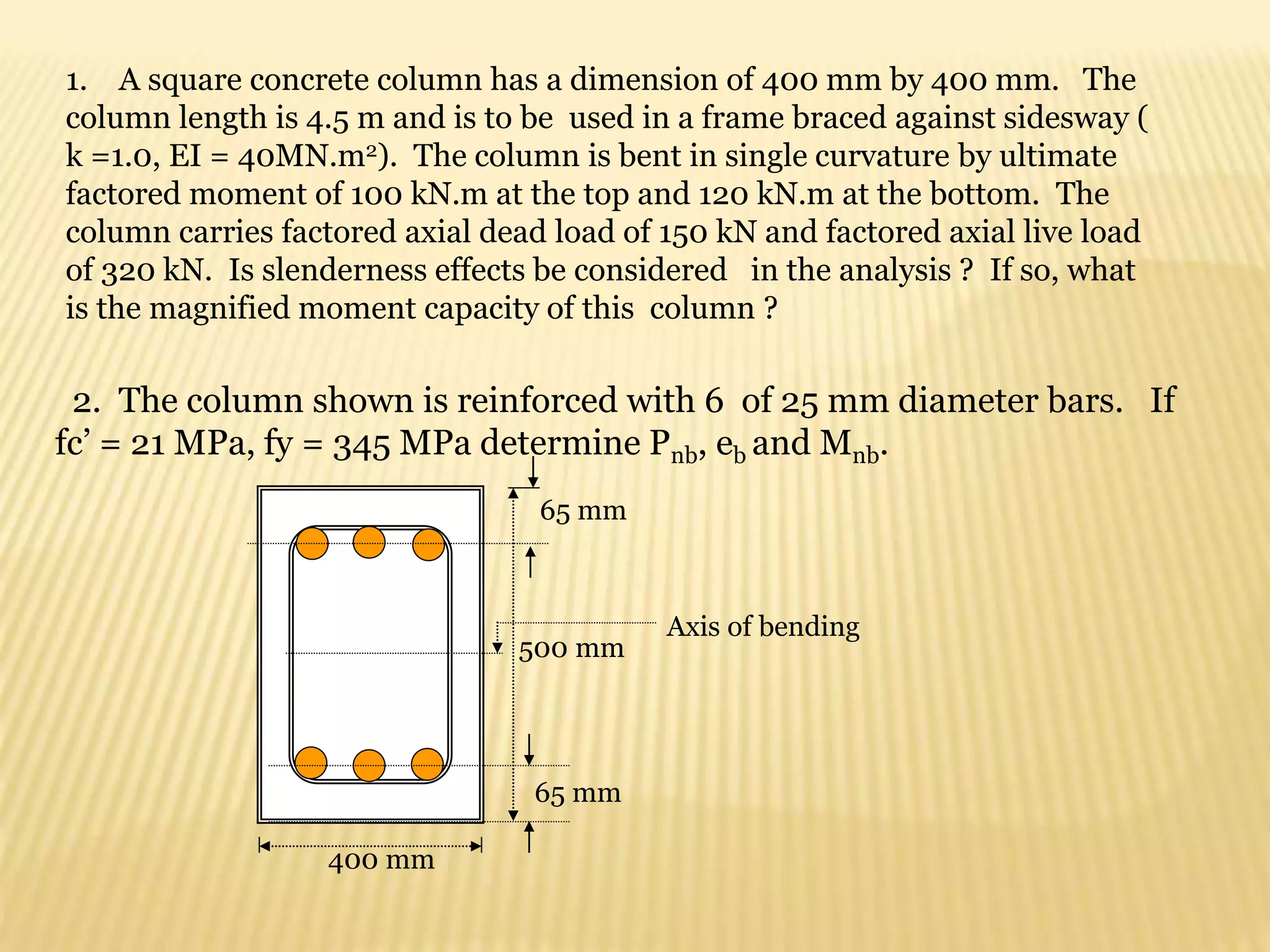
![1.A square tied column 300 mm by 300 mm is reinforced with 6 of 20 mm
bars with fc’ = 20.7 MPa and fy = 345 MPa. Determine the following :
a) Ultimate axial load capacity of the column.
b) spacing of 10 mm lateral ties
Concrete Design
Semi- Final Exam
Pu =Ф0.80{0.85fc’(Ag-Ast) + Astfy} 2
2
95
.
1884
4
)
20
(
6 mm
Ast
kN
Pu 38
.
1232
1000
)}
345
(
95
.
1884
]
95
.
1884
)
300
)(
300
)[(
7
.
20
(
85
.
0
){
80
.
0
(
7
.
0
mm
S 400
)
20
(
16
mm
S 480
)
10
(
48
mm
S 300
Use S = 300 mm
Spacing of 10 mm ties](https://image.slidesharecdn.com/reinforcedconcretearki-230107090713-5546eb80/75/reinforced-concrete-arki-ppt-384-2048.jpg)
![2. Calculate the ultimate axial load capacity of the composite column shown
below .fc’=21 MPa, Fy=250 MPa,fy =350MPa. Reinforcing bars consist of 8 of
20 mm diameter bars.
Properties of W 10 x 150
Area = 27000 mm2
Depth = 250 mm
W10 x 150
400 mm
400 mm
y
WF
y
s
c
u F
A
f
A
A
fc
P
'
85
.
0
85
.
0
2
2
2513
4
]
)
20
[(
8
mm
As
)
250
(
27000
)
350
(
2513
)
130487
)(
21
(
85
.
0
85
.
0
)
7
.
0
(
u
P
2
130487
2513
27000
)
400
(
400 mm
Ac
kN
N
Pu 52
.
925
,
5
5925452
](https://image.slidesharecdn.com/reinforcedconcretearki-230107090713-5546eb80/75/reinforced-concrete-arki-ppt-385-2048.jpg)


![]
7
.
1
7
.
1
4
.
1
[
75
.
0
2 W
L
D
s M
M
M
M
m
kN
M s .
75
.
114
)]
90
(
7
.
1
)
0
(
7
.
1
)
0
(
4
.
1
[
75
.
0
2
Solution to #2
kN
P
P L
D 470
320
150
]
7
.
1
4
.
1
[
Specified in the previous
problem
kN
P
P
P
P W
L
D
u 87
.
511
)]
125
(
7
.
1
470
[
75
.
0
]
7
.
1
7
.
1
4
.
1
[
75
.
0
97
.
0
)
5
.
19495
(
7
.
0
87
.
511
1
933
.
0
1
c
u
m
b
P
P
C
m
kN
M
M
M s
s
b
b
c .
15
.
231
)
75
.
114
(
0
.
1
)
120
(
97
.
0
2
2
0
.
1
s
Frame is braced against sidesway](https://image.slidesharecdn.com/reinforcedconcretearki-230107090713-5546eb80/75/reinforced-concrete-arki-ppt-395-2048.jpg)


![ax
Ac
2
1
475
450
a
x
1
.
947
.
0 EQ
a
x
)
947
.
0
(
2
1
45
.
11827 a
a
mm
a 04
.
158
mm
a
c 93
.
185
85
.
0
04
.
158
1
From the strain diagram
c
c
s
400
003
.
0
2000000
s
s
f
93
.
185
93
.
185
400
003
.
0
)
200000
(
s
f
y
s f
MPa
f
8
.
690 tension steel yields at failure
By similar triangles
m
kN
a
f
A
M y
s
u .
1
.
55
10
)
3
04
.
158
]
2
[
400
(
345
)
2
.
603
(
9
.
0
)
3
2
400
( 6
](https://image.slidesharecdn.com/reinforcedconcretearki-230107090713-5546eb80/75/reinforced-concrete-arki-ppt-405-2048.jpg)

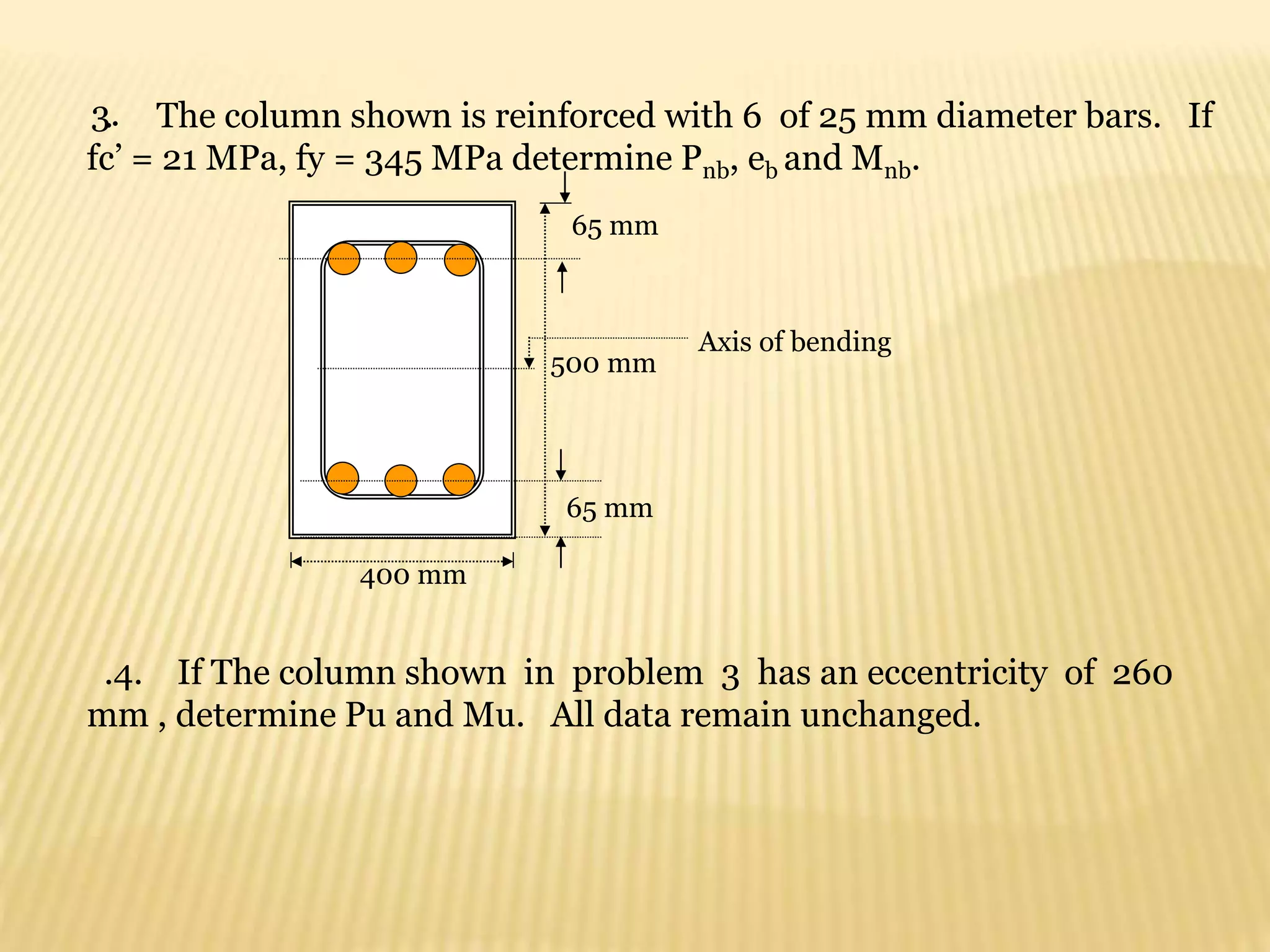
![2. A doubly reinforced rectangular concrete beam has b =350 mm,d =600mm,
fc’=27.5 MPa, fy = 345 MPa, As =3625 mm2, As’ = 775mm2 ,covering for tension
and compression bars 80 mm and 63 mm respectively. If the beam is an interior
span of a three span continuous beam supporting a service dead load of 20 kN/m
(weight included) determine the maximum uniformly distributed live load it can
support on an average clear span of 5.0 m. Use NSCP moment coeffecients.
mm
b
fc
f
A
a
y
s
18
.
120
350
)
5
.
27
(
85
.
0
)
345
(
2850
'
85
.
0
1
y
s f
MPa
a
d
a
f
65
.
332
18
.
120
)])
63
(
85
.
0
[
18
.
120
(
600
)
(
600 '
1
'
2
1 2850
775
3625
' mm
As
As
As
Compression steel does not yield at failure
∑Fx =0 0.85fc’ab + As’fs’ = Asfy
0.85(27.5)350a + 775fs’ = 3625(345)
10.56a +fs’ = 1613.7
fs’ =1613.7 – 10.56 a EQ.1](https://image.slidesharecdn.com/reinforcedconcretearki-230107090713-5546eb80/75/reinforced-concrete-arki-ppt-407-2048.jpg)
![a
a
a
d
a
fs
)])
63
(
85
.
0
[
(
600
)
(
600 '
1
'
2
.
)
55
.
53
(
600
'
EQ
a
a
fs
2
.
1
. EQ
EQ
a
a
a
)
55
.
53
(
600
56
.
10
7
.
1613
32130
600
56
.
10
7
.
1613 2
a
a
a
0
32130
7
.
1013
56
.
10 2
a
a
0
6
.
3042
96
2
a
a
mm
a 12
.
121
2
)
6
.
3042
(
4
)
96
(
96 2
12
.
121
)
55
.
53
12
.
121
(
600
'
s
f
y
s f
MPa
f
7
.
334
'
)
2
(
1
1
a
d
f
As
Mu y
)
'
(
'
'
2 d
d
fs
As
Mu
6
1
10
)
2
12
.
121
600
)(
345
)
2850
(
9
.
0
Mu
m
kN
Mu .
36
.
477
1
6
2
10
)
63
600
(
7
.
334
)
775
(
9
.
0
Mu
m
kN
Mu .
36
.
125
2
m
kN
Mu
Mu
Mu .
72
.
602
2
1
2
'
max 6
.
6500
'
75
.
0 mm
f
fs
A
bd
p
A
y
s
b
s
0365
.
0
345
)
345
600
(
)
600
(
7
.
334
)
5
.
27
(
85
.
0
b
p](https://image.slidesharecdn.com/reinforcedconcretearki-230107090713-5546eb80/75/reinforced-concrete-arki-ppt-408-2048.jpg)