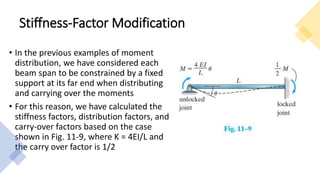
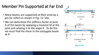
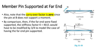
RESORT MANAGEMENT AND RESERVATION SYSTEM PROJECT REPORT.pdf
Topic4_Moment Distribution with Stiffness Factor Modification.pptx
1. CED 426
Structural Theory II
Lecture 18
Moment Distribution:
Stiffness-Factor Modification and Frames no Sideways
Mary Joanne C. Aniñon
Instructor
2. Stiffness-Factor Modification
• In the previous examples of moment
distribution, we have considered each
beam span to be constrained by a fixed
support at its far end when distributing
and carrying over the moments
• For this reason, we have calculated the
stiffness factors, distribution factors, and
carry-over factors based on the case
shown in Fig. 11-9, where K = 4EI/L and
the carry over factor is 1/2
3. Stiffness-Factor Modification
• In some cases, it is possible to modify the stiffness factor of a span
and thereby simplify the process of moment distribution.
• Three cases where this frequently occurs will be considered:
a) Member Pin Supported at Far End
b) Symmetric Beam and Loading
c) Symmetric Beam with Antisymmetric loading
4. • Many beams are supported at their ends by a
pin (or roller) as shown in Fig. 11–10a.
• We can determine the stiffness factor at joint
A of this beam by applying a moment M at the
joint and relating it to the angle 𝜃 . To do this
we must find the shear in the conjugate beam
at A’
Member Pin Supported at Far End
5. • From the conjugate beam Fig. 11-10b, we have
Member Pin Supported at Far End
6. • Also, note that the carry-over factor is zero since
the pin at B does not support a moment.
• By comparison, then, if the far end were fixed
supported, the stiffness factor K = 4EI/L would
have to be modified by 3/4 to model the case of
having the far end pin supported.
Member Pin Supported at Far End
7. Symmetric Beam and Loading
• If a beam is symmetric with respect to both its loading and geometry,
the bending moment diagram for the beam will also be symmetric.
• As a result, a modification of the stiffness factor for the center span
can be made, so that moments in the beam only have to be
distributed through a joint lying on either half of the beam.
8. Symmetric Beam and Loading
• To develop the appropriate stiffness-factor modification, consider the
beam shown in Fig.11-11a. Due to the symmetry, the internal
moments at B and C are equal. Assuming this value to be M, the
conjugate beam for span BC is shown in Fig.11-11b
10. Symmetric Beam with Antisymmetric loading
• If the asymmetric beam is subjected to antisymmetric loading, the
resulting moment diagram will be antisymmetric.
• Considering the beam Fig. 11-12a, due to the antisymmetric loading, the
internal moment at B is equal but opposite to that of C
• Assuming the value to be M, the conjugate beam for its center span BC is
shown in Fig. 11-12b.
12. Example 1
• Determine the internal moments at the supports for the beam shown
in Fig. 11-13a
13. Example 1
Step 1.a. Identify the joints and spans in the
beam: A, B, C, D and span AB, BC, CD
Step 1.b. Calculate member and joint stiffness
factors for each span.
• By inspection, the beam and loading are symmetrical
• We will apply K=2EI/L to calculate the stiffness factor of the center span BC and therefore
use only the left half of the beam for analysis.
• The analysis can be shortened even further by using K = 3EI/L for calculating the stiffness of
segment AB since the far end A is pinned.
14. Example 1
Step 1.b. Calculate member and joint stiffness
factors for each span.
Step 1.c. Determine the distribution factors (DF).
K =
4𝐸𝐼
𝐿
𝐷𝐹 =
𝐾
𝐾
16. Example 1
FEMBA
FEMAB =0 FEMBC FEMCB
FEMCD FEMDC =0
Joint A B
Member AB BA BC
DF 1 0.667 0.333
FEM
Dist.
0
0
60
48.9
-133.33
24.4
∑M 0 108.9 -108.9
• The data are listed in the table.
• Calculating the stiffness factors as
shown considerably reduces the
analysis, since only joint B must be
balanced and carry-overs to joint A
and C are not necessary.
17. Moment Distribution For Frames: No Sidesway
• Application of the moment distribution method for frames having no
sideways follows the same procedure as that given for beams.
• To minimize the chance for errors, it is suggested that the analysis be
arranged in a tabular form, as in the previous examples
• The distribution of moments can be shortened if the stiffness factor of a
span can be modified.
18. Example 2
• Determine the internal moments at the joints of the frame shown in Fig.
11-15a. There is a pin at E and D and a fixed support at A. EI is constant
19. • By inspection, the pin at E will
prevent the frame from sidesway.
Example 2
20. Example 2
Step 1.a. Identify the joints and spans in the beam:
A, B, C, D, E and span AB, BC, CD, CE
Step 1.b. Calculate member and joint stiffness
factors for each span.
The stiffness factors of CD and CE can be calculated
using K = 3EI/L since the far ends D and E are
pinned.
K =
4𝐸𝐼
𝐿
21. Example 2
Step 1.c. Determine the distribution factors (DF).
𝐷𝐹 =
𝐾
𝐾
𝐷𝐹𝐵𝐶 =
4𝐸𝐼/6
4𝐸𝐼
5
+
4𝐸𝐼
6
= 0.455