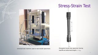
- Chapter II of the Mechanics of Materials textbook covers stress and strain under axial loading. It discusses basic theory of axial deformation, statically determinate and indeterminate structures, and thermal effects on axial deformation.
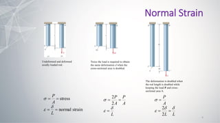
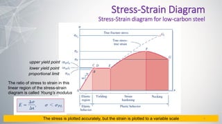
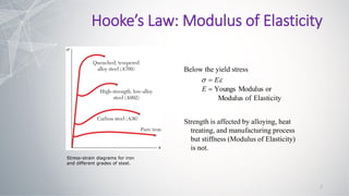
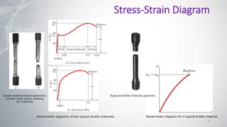
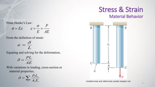
- Stress-strain diagrams are presented, showing the linear elastic region below the yield point, as well as plastic deformation regions. Hooke's law relates stress and strain through Young's modulus.
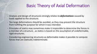
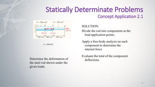
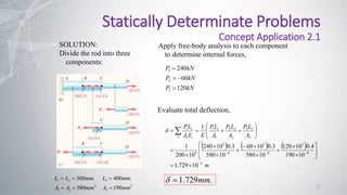
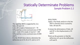
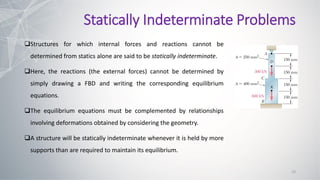
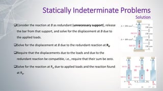
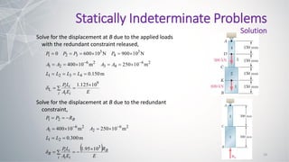
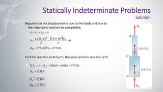
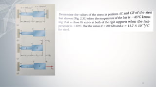
- Structures can be statically indeterminate if they have more supports than required for equilibrium. Internal forces are found using compatibility of deformations considering the structure as deformable.