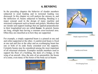
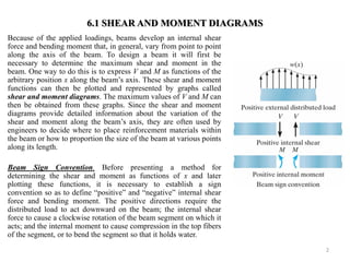
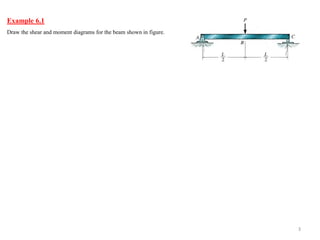
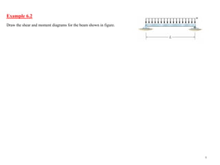
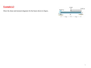
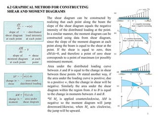
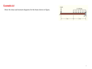
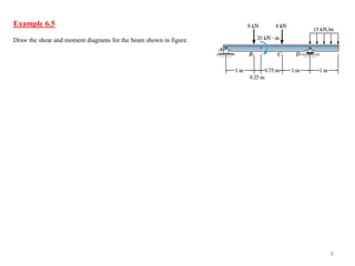
6. BENDING 
In the preceding chapters the behavior of slender members subjected to axial loading and to torsional loading was discussed. In this chapter we will analyze the stresses in, and the deflection of, beams subjected to bending. Bending is a major concept used in the design of many machine and structural component such as beams and girders. Members that are slender and support loadings that are applied perpendicular to their longitudinal axis are called beams. In general, beams are long, straight bars having a constant cross-sectional area. Often they are classified as to how they are supported. 
For example, a simply supported beam is a pinned at one end and roller-supported at the other. A cantilevered beam is fixed at one end and free at the other and an overhanging beam has one or both of its ends freely extended over the supports. Certainly beams may be considered among the most important of all structural elements. Examples include members used to support the floor of a building, the deck of a bridge, or the wing of an aircraft. Also, the axle of an automobile, the boom of a crane, even many of the bones of the body act as beams. 
1
2 
Because of the applied loadings, beams develop an internal shear force and bending moment that, in general, vary from point to point along the axis of the beam. To design a beam it will first be necessary to determine the maximum shear and moment in the beam. One way to do this is to express V and M as functions of the arbitrary position x along the beam’s axis. These shear and moment functions can then be plotted and represented by graphs called shear and moment diagrams. The maximum values of V and M can then be obtained from these graphs. Since the shear and moment diagrams provide detailed information about the variation of the shear and moment along the beam’s axis, they are often used by engineers to decide where to place reinforcement materials within the beam or how to proportion the size of the beam at various points along its length. 
Beam Sign Convention. Before presenting a method for determining the shear and moment as functions of x and later plotting these functions, it is necessary to establish a sign convention so as to define “positive” and “negative” internal shear force and bending moment. The positive directions require the distributed load to act downward on the beam; the internal shear force to cause a clockwise rotation of the beam segment on which it acts; and the internal moment to cause compression in the top fibers of the segment, or to bend the segment so that it holds water. 
6.1 SHEAR AND MOMENT DIAGRAMS
3 
Example 6.1 
Draw the shear and moment diagrams for the beam shown in figure.
4 
Example 6.2 
Draw the shear and moment diagrams for the beam shown in figure.
5 
Example 6.3 
Draw the shear and moment diagrams for the beam shown in figure.
6 
The shear diagram can be constructed by realizing that each point along the beam the slope of the shear diagram equals the negative intensity of the distributed loading at the point. In a similar manner, the moment diagram can be constructed using data from shear diagram, since the slope of the moment diagram at each point along the beam is equal to the shear at the point. If the shear is equal to zero, then dM/dx=0, and therefore a point of zero shear corresponds to a point of maximum (or possibly minimum) moment. 
6.2 GRAPHICAL METHOD FOR CONSTRUCTING SHEAR AND MOMENT DIAGRAMS 
Area under the distributed loading curve between A and B is equal to the change in shear between these points. Or stated another way, if the area under the loading curve is positive, due to a positive w, then the change in shear will be negative. Similarly the area under the shear diagram within the region from A to B is equal to the change in moments between A and B. 
*If Mo is applied counterclockwise, M is negative so the moment diagram will jump downward.likewise, when Mo acts clockwise, the jump will be upward.
7 
Example 6.4 
Draw the shear and moment diagrams for the beam shown in figure.
8 
Example 6.5 
Draw the shear and moment diagrams for the beam shown in figure.

Mm210(6)

  • 1.
    6. BENDING Inthe preceding chapters the behavior of slender members subjected to axial loading and to torsional loading was discussed. In this chapter we will analyze the stresses in, and the deflection of, beams subjected to bending. Bending is a major concept used in the design of many machine and structural component such as beams and girders. Members that are slender and support loadings that are applied perpendicular to their longitudinal axis are called beams. In general, beams are long, straight bars having a constant cross-sectional area. Often they are classified as to how they are supported. For example, a simply supported beam is a pinned at one end and roller-supported at the other. A cantilevered beam is fixed at one end and free at the other and an overhanging beam has one or both of its ends freely extended over the supports. Certainly beams may be considered among the most important of all structural elements. Examples include members used to support the floor of a building, the deck of a bridge, or the wing of an aircraft. Also, the axle of an automobile, the boom of a crane, even many of the bones of the body act as beams. 1
  • 2.
    2 Because ofthe applied loadings, beams develop an internal shear force and bending moment that, in general, vary from point to point along the axis of the beam. To design a beam it will first be necessary to determine the maximum shear and moment in the beam. One way to do this is to express V and M as functions of the arbitrary position x along the beam’s axis. These shear and moment functions can then be plotted and represented by graphs called shear and moment diagrams. The maximum values of V and M can then be obtained from these graphs. Since the shear and moment diagrams provide detailed information about the variation of the shear and moment along the beam’s axis, they are often used by engineers to decide where to place reinforcement materials within the beam or how to proportion the size of the beam at various points along its length. Beam Sign Convention. Before presenting a method for determining the shear and moment as functions of x and later plotting these functions, it is necessary to establish a sign convention so as to define “positive” and “negative” internal shear force and bending moment. The positive directions require the distributed load to act downward on the beam; the internal shear force to cause a clockwise rotation of the beam segment on which it acts; and the internal moment to cause compression in the top fibers of the segment, or to bend the segment so that it holds water. 6.1 SHEAR AND MOMENT DIAGRAMS
  • 3.
    3 Example 6.1 Draw the shear and moment diagrams for the beam shown in figure.
  • 4.
    4 Example 6.2 Draw the shear and moment diagrams for the beam shown in figure.
  • 5.
    5 Example 6.3 Draw the shear and moment diagrams for the beam shown in figure.
  • 6.
    6 The sheardiagram can be constructed by realizing that each point along the beam the slope of the shear diagram equals the negative intensity of the distributed loading at the point. In a similar manner, the moment diagram can be constructed using data from shear diagram, since the slope of the moment diagram at each point along the beam is equal to the shear at the point. If the shear is equal to zero, then dM/dx=0, and therefore a point of zero shear corresponds to a point of maximum (or possibly minimum) moment. 6.2 GRAPHICAL METHOD FOR CONSTRUCTING SHEAR AND MOMENT DIAGRAMS Area under the distributed loading curve between A and B is equal to the change in shear between these points. Or stated another way, if the area under the loading curve is positive, due to a positive w, then the change in shear will be negative. Similarly the area under the shear diagram within the region from A to B is equal to the change in moments between A and B. *If Mo is applied counterclockwise, M is negative so the moment diagram will jump downward.likewise, when Mo acts clockwise, the jump will be upward.
  • 7.
    7 Example 6.4 Draw the shear and moment diagrams for the beam shown in figure.
  • 8.
    8 Example 6.5 Draw the shear and moment diagrams for the beam shown in figure.