This powerpoint presentation deals mainly about bearing stress, its concept and its applications.
Members:
BARIENTOS, Lei Anne
MARTIREZ, Wilbur
MORIONES, Jan Ebenezer
NERI, Laiza Paulene
Sir Romeo Alastre - MEC32/A1
Prepared by madam rafia firdous. She is a lecturer and instructor in subject of Plain and Reinforcement concrete at University of South Asia LAHORE,PAKISTAN.
Shear and torsion .. it provide good knowledge in engineering mechanics and strength of material. The students who expert in this I am sure that he can perform well in designing mechanical engineering components.
Aquí se estudian y deducen las relaciones entre el momento flexionante y los esfuerzos normales por flexión que se producen, y entre fuerzas cortantes verticales y los esfuerzos cortantes, y asimismo, diversos temas de importancia práctica en el diseño de vigas.
Industrial Training at Shahjalal Fertilizer Company Limited (SFCL)MdTanvirMahtab2
This presentation is about the working procedure of Shahjalal Fertilizer Company Limited (SFCL). A Govt. owned Company of Bangladesh Chemical Industries Corporation under Ministry of Industries.
Courier management system project report.pdfKamal Acharya
It is now-a-days very important for the people to send or receive articles like imported furniture, electronic items, gifts, business goods and the like. People depend vastly on different transport systems which mostly use the manual way of receiving and delivering the articles. There is no way to track the articles till they are received and there is no way to let the customer know what happened in transit, once he booked some articles. In such a situation, we need a system which completely computerizes the cargo activities including time to time tracking of the articles sent. This need is fulfilled by Courier Management System software which is online software for the cargo management people that enables them to receive the goods from a source and send them to a required destination and track their status from time to time.
CFD Simulation of By-pass Flow in a HRSG module by R&R Consult.pptxR&R Consult
CFD analysis is incredibly effective at solving mysteries and improving the performance of complex systems!
Here's a great example: At a large natural gas-fired power plant, where they use waste heat to generate steam and energy, they were puzzled that their boiler wasn't producing as much steam as expected.
R&R and Tetra Engineering Group Inc. were asked to solve the issue with reduced steam production.
An inspection had shown that a significant amount of hot flue gas was bypassing the boiler tubes, where the heat was supposed to be transferred.
R&R Consult conducted a CFD analysis, which revealed that 6.3% of the flue gas was bypassing the boiler tubes without transferring heat. The analysis also showed that the flue gas was instead being directed along the sides of the boiler and between the modules that were supposed to capture the heat. This was the cause of the reduced performance.
Based on our results, Tetra Engineering installed covering plates to reduce the bypass flow. This improved the boiler's performance and increased electricity production.
It is always satisfying when we can help solve complex challenges like this. Do your systems also need a check-up or optimization? Give us a call!
Work done in cooperation with James Malloy and David Moelling from Tetra Engineering.
More examples of our work https://www.r-r-consult.dk/en/cases-en/
Forklift Classes Overview by Intella PartsIntella Parts
Discover the different forklift classes and their specific applications. Learn how to choose the right forklift for your needs to ensure safety, efficiency, and compliance in your operations.
For more technical information, visit our website https://intellaparts.com
Vaccine management system project report documentation..pdfKamal Acharya
The Division of Vaccine and Immunization is facing increasing difficulty monitoring vaccines and other commodities distribution once they have been distributed from the national stores. With the introduction of new vaccines, more challenges have been anticipated with this additions posing serious threat to the already over strained vaccine supply chain system in Kenya.
Immunizing Image Classifiers Against Localized Adversary Attacksgerogepatton
This paper addresses the vulnerability of deep learning models, particularly convolutional neural networks
(CNN)s, to adversarial attacks and presents a proactive training technique designed to counter them. We
introduce a novel volumization algorithm, which transforms 2D images into 3D volumetric representations.
When combined with 3D convolution and deep curriculum learning optimization (CLO), itsignificantly improves
the immunity of models against localized universal attacks by up to 40%. We evaluate our proposed approach
using contemporary CNN architectures and the modified Canadian Institute for Advanced Research (CIFAR-10
and CIFAR-100) and ImageNet Large Scale Visual Recognition Challenge (ILSVRC12) datasets, showcasing
accuracy improvements over previous techniques. The results indicate that the combination of the volumetric
input and curriculum learning holds significant promise for mitigating adversarial attacks without necessitating
adversary training.
Welcome to WIPAC Monthly the magazine brought to you by the LinkedIn Group Water Industry Process Automation & Control.
In this month's edition, along with this month's industry news to celebrate the 13 years since the group was created we have articles including
A case study of the used of Advanced Process Control at the Wastewater Treatment works at Lleida in Spain
A look back on an article on smart wastewater networks in order to see how the industry has measured up in the interim around the adoption of Digital Transformation in the Water Industry.
Saudi Arabia stands as a titan in the global energy landscape, renowned for its abundant oil and gas resources. It's the largest exporter of petroleum and holds some of the world's most significant reserves. Let's delve into the top 10 oil and gas projects shaping Saudi Arabia's energy future in 2024.
1. 5-1 INTRODUCTION
In this chapter we derive the relations between the bending
moment and the flexure stress it causes, and between the vertical
shear and the shearing stresses. In deriving these relations, we
make the following assumptions:
I. The plane sections of the beam remain plane.
2. The material in the beam is homogeneous and obeys
Hooke's law.
3. The moduli of elasticity for tension and compression are
equal.
4. The beam is initially straight and of constant cross
section.
5. The plane of loading must contain a principal axis of the
beam cross section and the loads must be perpendicular to
the longitudinal axis of the beam.
The application and limits of these assumptions will be
discussed in succeeding articles as the reason for them becomes
apparent.
5-2 DERIVATION OF FLEXURE FORMULA
The stress caused by the bending moment is known as bending or
flexure stresses, and the relation between these stresses and the
bending moment is expressed by the flexure formula. The
derivation of this relation follows the procedure developed in
deriving the torsion formula (see Art. 3-2); that is, the elastic
deformations plus Hooke's law determine the manner of stress
variation, after which the conditions of equilibrium then establish
the relation between stress and load.
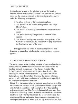
Figure 5-1a shows two adjacent sections, ab and cd, separated by
the distance dx. Because of the relative to each other straight and
undistorted in accordance with assumption 1 of the preceding
article. shortened, and fiber bd at the bottom is lengthened. them
is Because of bending caused by load P, section ab and cd rotated
relative to each other by the amount dƟ as shown in figure but
remain straight and undistorted in accordance with assumption 1
of the preceeding article. Fiber ac at the top is shortened and fiber
2. bd at the lengthend. Somewhere between them is located fiber ef,
whose length is unchanged. Drawing the line c'd' through f
parallel to ab shows that fiber ac is shortened an amount cc' and
is in compression, and that fiber bd is lengthened by an amount
d'd and is in tension.
(a)
dx
a c
b d
P
R1 R2
Neutral surface
y
𝜌
a
e f
c c’
g h
d𝜃
b dd’
O
3. (b)
Figure 5-1 Deformations.
The plane containing fibers like ef is called the neutral
surface because such fibers remain unchanged in length and
hence carry no stress. It will shown shortly that this neutral
surface contains the centroids of all transevarse sections.
Consider now the deformation of a typical fiber gh
located y units from the neutral surface. Its elongation hk is the
arc of a circle of radius y subtended by the angle dB and is
given by
δ = hk = y dƟ
The strain is found by dividing the deformation by the original
length ef of the fiber:
ϵ =
𝜹
𝑳
=
𝒚 𝒅Ɵ
𝒆𝒇
If we denote the radius of curvature of the neutral surface by p,
the curved length ef is equal to dƟ; from which the strain becomes
ϵ =
𝒚 𝒅Ɵ
𝝆𝒅Ɵ
=
𝒚
𝝆
Assuming that the material is homogeneous and obeys Hooke's
law (assumption 2), the stress in fiber gh is given by
σ = Eϵ = (
𝑬
𝝆
)𝒚
Equation (a) indicates that the stress in any fiber varies directly
with its location y from the neutral surface, since it is assumed
that the modulus of elasticity E is equal in tension and
compression (assumption 3) and the radius of curvature p of the
neutral surface is independent of the location y of the fiber.
4. However' he stresses must not exceed the proportional limit, for
this would invalidate Hooke's law on which this stress variation is
based.
To complete the derivation of the flexure formula, we apply
the conditions of equilibrium. As we saw in Art. 4-3, the external
loads that act to one side of an exploratory section are balanced by
the resisting shear Vr and the resisting moment Mr. To create this
balance, a typical element in the exploratory section is subjected to
the forces shown in the pictorial sketch* in Fig. 5-2. The line of
intersection the neutral surface and the transverse exploratory
section is called the neutral axis, abbreviated NA.
LongitudinalPlane
Of bendingloads
y
y
z
z
Neutral
Surface
𝜎𝑥 𝑑𝐴𝜏 𝑥𝑦 𝑑𝐴
𝜏 𝑥𝑧 𝑑𝐴
x
NA
5. Figure 5-2 Forces acting on a typical element of the cross
section of a beam.
To satisfy the conditions that the external loads have no x
components
(assumption 5), we must have
[Σ Fx=0]
where is equivalent to c in Eq. (a). On replacing by
𝑬𝒚
𝝆
, we obtain
ʃρx dA =0
The constant ratio E/ρ is written outside the integral sign. Since y
dA is the
moment of the differential area dA about the neutral axis, the
integral y dA is the total moment of area. Hence
𝑬
𝝆
𝑨𝒚̅ = 𝟎
However, since only 𝑦̅ in this relation can be zero, we conclude
that the distance from the neutral axis (which is the reference axis)
to the centroid of the cross sectional area must be zero; that is, the
neutral axis must contain the centroid of the cross-sectional area.
P
R
𝑣𝑟
𝑤0
Mr
6. The condition that ΣFy = 0, resulting in V = Vr, leads to
the shear formula, the derivation of which is postponed until
later. It should observed here that the resisting shear Vr is the
summation of the shearing forces 𝜏xy dA; that is, Vr = ∫ 𝝉 𝒙𝒚 𝒅𝑨
The condition Σ FZ = 0 leads to ∫ 𝝉 𝒙𝒚 dA = 0. Since the
loading has no z components, the system of shear forces 𝜏xz dA
must self-balancing. We examine this in greater detail in Art.
13-8, where the plane of loading may offset from the xy plane
but remains parallel to it. In those cases, the loading causes a
moment about the x axis which is balanced by ∫ 𝒚 ( 𝝉 𝒙𝒛 dA)-
∫ 𝒛 (𝝉 𝒙𝒚 dA) in order to satisfy the condition Σ Mx = 0. This
condition is automatically satisfied for sections that are
symmetrical about the y axis because then the element under
discussion has a symmetrically placed counterpart so the
integrals are equal to zero. As a result, the plane of loading for
sections symmetrical about the y axis must coincide with the xy
plane, or the beam will twist.
We consider next the condition Σ My = 0. The external
loads have no moment about the y axis nor do the internal forces
dA and ∫ 𝝉 𝒙𝒛 dA. Therefore
[Σ My = 0 ] ∫ 𝒛 𝝈 𝒙 𝒅𝑨= 0
Again, replacing ax by
𝑬𝒚
𝝆
, we have
𝑬
𝝆
ʃ zydA = 0
The integral ʃzydA is the product of inertia Pzy, which is zero only
if y or z is an axis of symmetry or a principal axis. This is the
justification for assumption 5.
The final condition of equilibrium, ΣMz = 0, requires that
the bending moment be balanced by the resisting moment; that is,
M = Mr. The resisting moment about the neutral axis of a typical
element y(σx dA), this condition requires that
M=ʃ y(σx dA)
7. which, by replacing ax by
𝑬𝒚
𝝆
from Eq. (a), becomes
M=
𝑬𝒚
𝝆
ʃ y2 dA
Since ∫ 𝐲 𝟐
dA is defined as I, the moment of inertia of the area
about a reference axis, which here is the neutral axis (equivalent
to the centroidal axis), we finally obtain.
M =
𝑬𝑰
𝝆
(b)
Observe now that it was necessary in Art. 4-2 to specify the
centroidal axis of the exploratory section as the axis about which
the bending moment is computed in order to obtain a common
axis for computing and equating M and Mr.
The usual form of writing Eq. (b) is
𝟏
𝝆
=
𝑴
𝑬𝑰
……………………..(5-1)
which we shall use in Arts. 6-2 and 6-3 as the basis for
determining deflections in beams. Because curvature is equal to
the reciprocal of the radius of curvature, Eq. (5-1) indicates that
curvature is directly proportional to bending moment, an
observation that we have already used in checking the sign of the
bending moment with the shape of the deflected beam positive
curvature, which is concave upward, correlating with a positive
bending moment, and vice versa.
Equating the ratio
𝑬
𝝆
from Eq. (5-1) with its value from Eq.
(a), we have
8. 𝑬
𝝆
=
𝑴
𝑰
=
𝝈
𝒚
which leads directly to the flexure formula
ρ=
𝑴𝒚
𝑰
………………. (5-2)
This formula indicates that the flexure stress in any section varies
directly with the distance of the section from the neutral axis. In a
more common form of the flexure formula, y is replacedby the
distance c, which is defined as the distance from the neutral axis
to the remotest element. With this change, the maximum flexure
stress in any section is given by
Max. ρ =
𝑴𝒄
𝑰
………..(5-28)
If I/c is called the section modulus and denoted by S,
another common variation of the flexure formula is
Max. ρ =
𝑴𝒄
𝑰
=
𝑴
𝑺
…… (5-2b)
This variation is useful for beams of constant cross section, as it
shows that maximum flexure stress occurs at the section of the
maximum tending moment. Various values of section modulus
for common cross sections are listed in Table 5-1
c
c
k
k
e
C
T
b
h
ℎ
2
ℎ
2
NA
Area in tension
Area in compression
10. An interesting analysis, similar to that we shall use later in
analyzing reinforced concrete beams is to consider the variation
in flexure stress over a rectangular cross section, as shown in
Fig. 5-3.
Because the horizontal summation of forces over a section
must be zero, the total compressive force C in the upper half of
the cross section is equal to the total tensile force Tin the lower
half. Thus the resisting moment Mr consists of the couple
composed of the equal, oppositely directed forces C and 'T. The
value of each of these forces is equal to the product of the
average stress multiply by the area. Therefore, since the average
stress in a linear stress distribution is one-half the maximum
stress.
T= C = (σavg.)(Area) = (
𝟏
𝟐𝝈
) ( 𝒃.
𝒉
𝟐
)
The forces C and T act through the centroid of the
triangular load distribution at a distance k from NA. Since
k =(
𝟐
𝟑𝒄
) =(
𝟐
𝟑
) (
𝒉
𝟑
) the moment arm of the resisting couple is e
= 2k = (
𝟐
𝟑𝒉
). Equating the bending moment to the resisting
moment, we have
M = Mr = Ce =Te
M=(
𝟏
𝟐𝝈
) ( 𝒃.
𝒉
𝟑
)(
𝟐
𝟑𝒉
)= ρ
𝒃𝒉 𝟐
𝟔
which agrees with Eq. (5-2b) for a rectangular section.
11. Modulus of Rupture
Equation (5-2a) may be used to compute the flexure stress in a
beam loaded to rupture in a testing machine. Because the
proportional limit øf the material is then exceeded, the stress
determined in this manner is not a true stress; nevertheless, the
fictitious stress so obtained is calledthe modulus of rupture. It
is used to compare the ultimate strengths of beams of various
sizes and materials.
ILLUSTRATIVE PROBLEMS
501. A beam 150 mm wide by 250 mm deep supports the loads
shown in Fig. 5-4. Determine the maximum flexural stress.
Solution: We begin by computing the maximum bending moment.
The shear diagram shows that zero shear occurs at x = 2 m. Using
the area of this diagram to
compute the bending moment, we have at x = 2 m
[ ∆M = (area)v ] Max. M = (
14+2
2
)(2) = 16 kN-m
It is unnecessary to draw the moment diagram.
12. Figure 5-4
We now apply the flexure formula, being careful to use consistent
units fot the various quantities. From Table 5-1 we find that the
section modulus is S=
𝒃𝒉 𝟐
𝟔
, so
[ σ =
𝑀
𝑆
=
6𝑀
𝑏ℎ2
] Max. σ =
6( 16∗103 )
(0.150)(0.250)2
= 10.24 MPa Ans.
502. A timber beam 4 in. wide by 12 in. high and 20 ft long carries
the loading shown In Fig. 5-5, If the maximum flexure stress is
1200 psi, for what maximum value of w0 will the shear be zero
under P, and what is the value of P?
Solution: To satisfy the given conditions, the shear diagram must
appear as shown, The maximum value of w0 to reduce the shear to
zero at P is determined from Eq. (4-3).
15kN
2m 1m
R1 =14kN R2 =19kN
6kN/m
2m
1m
2kN
13kN
-19kN
14kN
150mm
250mm
13. [ ∆V = (area)load ] 10w0 +
𝑃
4
= 15w0
which determines the following relation between P and w0:
P = 20 w0
The maximum bending moment occurs under P and is
[ ∆M = (area)v ] Max. M =
15
2
(15𝑤0) = 112.5w0 lb.ft
Converting bending moment to 1b-in. and applying the flexure
formula, we obtain,
[ M = σ
𝐼
𝑐
= σ
𝒃𝒉 𝟐
𝟔
] (112.5w0)(12) = 1200
(𝟒)(𝟏𝟐) 𝟐
𝟔
W0 = 85.3 lb/ft
Figure 5-5
15ft 5ft
R1 =10w0+p/4 R2
wo lb/ft
P
15ft
5ft
-P
-19kN
15w0 =10w0+p/4
4 in.
12in.
14. From relation (a), the value of P is
P = 20w0 = 20(85.3) = 1706 lb Ans.
5-3 ECONOMIC SECTIONS
In a beam having a rectangular or circular cross section, the fibers
near the neutral axis are under stressed compared with those at the
top or bottom. The fact that a large portion of the cross section is
thus under stressed makes it inefficient for resisting flexure.
The flexure formula, M =
𝜌𝐼
𝑐
, shows that if the area of a beam
of rectangular section (Fig. 5-6a) could be rearranged so as to
keep the same overall depth but have the shape shown in Fig. 5-
6b, the moment of inertia would be greatly increased, resulting
in a greater resisting moment. Physically, the increase
(a) (b) (c) (d)
Wide flange
(W shape)
I beam
(S shape)
15. (Fig. 5-6)
in resisting moment is due to more fibers being located at a greater
distance from the NA, for such fibers carry a greater stress and
have a larger moment arm about the NA to resist the applied
bending moment. However, the section in Fig. 5-6b is not
practical; the two parts of it would collapse together. It is
necessary to use some of the area to fix these parts in place
relative to each other, as in Fig. 5-6c. We see later that this web
area transmits practicallyall the vertical shear, and we shall learn
how to compute its dimensions.
Figure 5-6c represents a wide-flange beam (referred to as a W
shape). This is one of the most efficient structural shapes
manufactured because it not only
provides great flexural strength with minimum weight of material
but is highly efficient when used as a column (see Chapter I l).
Another structural shape is the I beam (referred to as an S shape)
in Fig. 5-6d; it preceded the wide flange and because it is not so
efficient has been largely replacedby the wide flange beam.
Properties of both these sections are given in Appendix B. In SI
units, a beam of either type is specified by stating its nominal
depth in millimeters and its nominal mass per unit length in
kilograms per meter. The designation W610 * 140, for example,
indicates a wide-flange beam with a nominal depth 610 mm and a
nominal mass per unit length of 140 kg/m. The tables in
Appendix B indicate that the actual depth of this beam is 617 mm
and its theoretical mass per unit length is 140.1 kg/m. In U.S.
Customary Units, a section is specified by stating its nominal
depth in inches followed by its weight in pounds per linear foot.
For example, a W36 * 300 is a wide-flange beam with a nominal
depth of 36 in. and weighing 300 lb/ft.The structural tables give
the dimensions and other properties of the cross-sectional area,
such as moment of inertia (I), section modulus (S), and radius of
gyration (r) for each principal axis of the section.
In selecting a structural section to be used as a beam, we note
that the resisting moment Mr =
𝜌𝐼
𝑐
= ρS must be equal to or
greater than the applied bending moment M. This may be
expressed as
16. S >=
𝑀
𝜌
…………………..5.3
Equation (5-3) indicates that a beam must be selected whose
section modulus is equal to or greater than the ratio of bending
moment to allowable stress.
The compression flanges of beams tend to buckle
horizontally sideways if the beam is too long. This buckling is a
column effect. (Columns will be discussed in Chapter 11.) When
this lateral deflection is prevented by the floor system or by
bracing the compression flanges at proper intervals, the full
allowable stresses may be used. Otherwise, the stresses should be
reduced. Formulas for the reduction of the allowable stress are
given in the specifications of the American Institute of Steel
Construction. Hereafter, we assume that all beams are properly
braced against lateral deflection.
ILLUSTRATIVE PROBLEM
528. What is the lightest W shape beam that will support the load
shown in Fig. 5-7 without exceeding a flexural stress of 120
MPa? Determine the actual maximum stress in the beam.
Assume the beam is properlybraced against lateral deflection.
Figure 5-7 Live load. (Applied load exclusive of
weight of beam.
4m
45 kN
2m
R1=15kN R2=30kN
15kN
-30kNShear diagram
17. Solution:
We begin by computing the reactions and sketching the shear
diagram.
The maximum moment occurs under the load and equals
15 * 4 = 60 kN - m.
Applying Eq. (5-3), we have
[ S ≥
𝑀
𝜌
]
S ≥
60∗103
120∗106
= 500* 10-6 m3
≥ 500 * 103 mm3
Referring to the table of properties of W shapes (Appendix B)
and starting at the bottom, we find that .the first beam whose
section modulus is greater than 500 * 103 mm3 is W200 * 52 with
S = 512 * 103 mm3. In the W250 group we find a W250 * 45 with
S = 534 * 103 mm3. Which is also satisfactory, as well as being
lighter. The W310 group lists a W310 * 39 beam with S = 549 *
103 mm3. The one is the best one, because the lightest suitable
beam in the remaining groups a mass per meter that is greater
than 38.7 kg/m, the mass per meter of the W 310 * 39 beam.
One may wonder why more than one size beam is
manufactured with approximately the same section modulus. The
explanation is that although the lightest beam is the cheapest on
the basis of weight alone, frequently headroom Clearances require
a beam of less depth than the lightest one.
The selection of the beam is not complete until a check
calculation is made that includes the weight of the beam. The
beam's resisting moment MB must equal to or greater than the sum
18. of the live-loadmoment ML caused by the applied loads and the
MB ≥ ML + MD dead-load moment MD caused by the dead
weight of the beam:
Dividing each term of this equation by the stress gives
𝑴 𝑩
𝝈
≥
𝑴 𝑳
𝝈
+
𝑴 𝑫
𝝈
Replacing
𝑴
𝝈
by the section modulus S, we obtain the governing
equation for design:
SB ≥ SL + SD
The weight of the beam in this example is 38.7 kg/m * 9.81
m/s2 = 380 N/m, which is not sufficient to change the location of
the maximum moment resulting from the combined live and dead
loads. Hence we compute the dead-load moment MD at x = 4 m
(Fig. 5-8). From the definition of bending moment, M = (Σ M)R,
we have
MD = (1.14)(2) - (0.380 * 2)(1) = 1.52 kN.m
or, from the shaded area of the shear diagram,
MD =
(1.14 + 0.38)
2
(2) = 1.52 kN.m2
Figure 5-8 Dead Load (Due to weight of beam)
R1=1.14 R2=1.14
6
m
2m
-1.14kN
-0.38kN
1.14kN
19. Therefore the section modulus required to support the
dead weight of the beam is
[ SD ≥
𝑴 𝑫
𝜌
]
SD ≥
1.52∗103
120∗106
= 12.7* 10-6 m3
≥ 12.7 * 103 mm3
Applying the governing equation,
[ SB ≥ SL + SD ] 549 * 103 > (500 + 12.7) * 10-6
we see that a W310 * 39 beam is satisfactory.
The actual maximum beam stress is easily determined from the
ratio of the beam modulus to the design modulus, namely,
[ M = σ’SB = σ(SL + SD) ]
σ’(549 * 10-6 ) = (120 ∗ 106
) [(500 + 12.7) * 10-6 ]
from which
σ’ =112 MPa
(Ans.)
5-4 FLOOR FRAMING
Probably the most common structural use of beams is to provide
support for the floors and frameworks of buildings. Figure 5-9
illustrates a typical detail in a home. The subfloor is supported by
floor joists (called floor beams in construction). The floor joists are
assumed to act as simply supported
20. They are supported by heavier beams called girders, which in turn
are supported by columns that transmit the loads to the foundation.
Figure : 5-9
a
a
a
L
Subfloor
Floor joint
Grinder
Column
21. The floor load per unit area is specified as p and varies from
2.5 kN/m2 (50 lb./ft2) for homes to as high as 25 kN/m2 (500 lb/ft2)
for industrial buildings If the floor joists are of length L and spaced
a distance a apart on centers, each joist is assumed to support the
loading of an area aL, shown shaded in 5-9. The loading on a
typical floor joist therefore is the uniformly distributed load shown
in Fig. 5-10. The total load W equals p, the load per unit area, acts
over the area aL This may be divided by the length L to give a
distributed load of intensity wo = pa.
Figure 5-10 Loading on a floor joint.
In steel construction, the same general plan is followed except
that the floor beams are usually riveted or bolted to the webs of
the girders as shown in fig. 1-13. The figures in the following
illustrative problem represent a small building and show how to
construct the loading diagrams for the various
L
𝑊 = 𝑝𝛼𝐿
𝑤0=p𝛼
22. ILLUSTRATIVE PROBLEM
537. Determine the loading diagrams for beams B-l, G-l, B-2, and
G-2 for the building whose partial floor plan is shown in Fig.
5- 11. The loading for each bay is indicated.
Solution:
Beams supporting only floor loads are designated B-l, B-2, and
so on. Beams that support the reactions of floor beams are called
girders and are denoted by G-1, G-2, and so on. At beam B-1, the
loading is 5 kN/m2 uniformly distributed over a length of 4 m and a
width of 2 m, resulting in the loading diagram shown in Fig. 5-12.
6m
6m
(B-3) (B-3) (B-3) (B-3) (B-3) (B-3)
Stair well 2m
2m 2m 2m 2m 2m
(G-2)
(G-1)
(B-2) (B-2)(B-1) (B-1)
10kN/𝑚2
10kN/𝑚2
10kN/𝑚2
10kN/𝑚2
10kN/𝑚2
10kN/𝑚25kN/𝑚2
5kN/𝑚2
5kN/𝑚2
5kN/𝑚2
23. Figure 5-12 Beam (B-l).
Beam G-l is a girder used to support one end of beams B-l and
framed into beams B-2. It is loaded bythe end reactions of B-l, as shown
in Fig. 5-13.
Figure 5-13 Girder (G- l).
R1=20kN R2=20kN
4m
W=5(2x4)=40kN
2m
20kN
2m
R1=20kN R2=20kN
20kN
2m
6m
24. Beam B-2 supports theend reaction of beam G-l, as well as half
the loadings in the bays adjacent to it. Its loading diagram therefore is
as shownin Fig. 5-14. Forthe first 2 m, beam B-2 supports atotal load
of 10 kN/m2 over a floor area 2 m * 1 m, equivalent to 20 kN applied
at 10 kN/m. The reaction of beam G-l is shown as a concentrated load
of 20 kN. For the rest of the beam, the loading is 15 kN/m computed
as the sum of the loadings per meter extending for 1 m into the 10-
kN/m2 bay and the 5-kN/m2 bay.
Figure 5-14 Beam (B-2).
The girder G-2 is loaded by the reactions of beams B-3 only,
as shown in Fig. 5-15. Verify that the reaction B-3 is 60 kN.
Figure : 5-15
5-5 UNSYMMETRICAL BEAMS
R1 R2
6m
20kN
15kN/m10kN/m
2m
60kN
2m
60kN
2m
6m
25. All the discussed so far have been symmetrical with respect to the
neutral axis. Because flexure stresses vary directly with distance
from the neutral axis— which is the centroidal axis—such beam
sections are desirable for materials that are equally strong in
tension and compression. However, for materials relatively weak
in tension and strong in compression, such as cast iron, it is
desirable to use beams that are unsymmetrical with respect to the
neutral axis. With such a cross section, the stronger fibers can be
located at a greater distance from the neutral axis than the weaker
fibers. The ideal treatment for such materials is to locate the
centroidal or neutral axis in such a position that the ratio of the
distances from it to the fibers in tension and in compression is
exactly the same as the ratio of the allowable stresses in tension
and in compression. The allowable stresses thus reach their
permitted values simultaneously.
ILLUSTRATIVE PROBLEMS
545. A cast-iron beam carries a uniformly distributed load on a
simple span. Compute the flange width b of the inverted T
section (Fig. 5-16) so that the allowable stresses σt = 30 MPa
and σc = 90 MPa reach their limits simultaneous
Figure 5-16.
L
𝑊0
20mm
120mm
20mm
b
yc
NA
yt
26. Solution:
The beam is concave upward so that the uppermost
fibers are incompression and the lowermost are intension.
As discussed inArt. 5-2,flexure stresses varydirectly with
their distance from the neutral axis. Therefore to cause σt
and σc to reach their limits simultaneously, we have
[
𝒚 𝒕
𝒚 𝒄
=
𝝈 𝒕
𝝈 𝒄
]
𝑦𝑡
𝑦 𝑐
=
30
90
=
1
3
Or, yc = 3 yt
Figure 5.16 shows that another relationbetween yt and
yc is
yt + yc = 140 mm
Solving Eqs. (a) and (b), we obtain
yt = 35 mm and yc = 105 mm
Now consider the T section to consist of the two shaded
rectangles. Since the neutral axis coincides with the centroidal
axis, we take moments of areas withrespect to an x axis through
the base of the flange and obtain
[ A𝑦̅ = Σ ay ]
27. (120 ×20 + b × 20)yt = (120 × 20)(20 + 60) + (b × 20)(10)
In this is substituted the value
yt = 35 mm,
which gives b = 216 mm
(Ans.)
546. Compute the maximum tensile and compressive stresses developed
in the tram that is loaded and has the cross-sectional properties as
shown in Fig. 5-17.
Figure 5.17
10ft
400𝑙𝑏/𝑓t
4ft
1000lb
R1=1600 lb R2=3400 lb
1600 lb
X=4 ft
-2400 lb
1000 lb
NA
2 in
6 in
I NA =64 𝑖𝑛4
28. Solution:
Sections of zero shear area at x= 4 ft and dx= 10 ft. The
bending moments at these are M4 = 3200 1b-ft and M10 = -4000 1b-
ft. Check these values.
The positive moment at x = 4 ft indicates curvature concave
upward; hence the upper fibers are in compressionand the lower
fibers are in tension. Applying Eq. (5-2) shows the flexure stresses
to be,
[ σ =
𝑴𝒚
𝑰
] σc =
(3200 × 12)(2)
60
= 1280 psi
σt =
(3200 × 12)(2)
60
= 3200 psi
At x = 10 ft, the negative bending moment is interpreted as
curvature concave downward; so the upper fibers are in tension and the
lower ones are in compression.
Having thus interpreted the sign of the bending moment, we
substitute the numerical value of the bending moment in Eq. (5-
2) and obtain the following flexure stresses,
[ σ =
𝑴𝒚
𝑰
] σc =
(4000 × 12)(2)
60
= 1680 psi
σt =
(4000 × 12)(2)
60
= 4000 psi
Hence, the maximum tensile stress is 3200 psi, occurring at
29. x = 4ft. and the maximum compressive stress is 4000 psi,occurring
at x = 10 ft. In an unsymmetrical section having a reversal in
curvature, the maximum stresses need not both at the section of
maximum bending moment. The stresses at each section of zero
shear must be investigated.
547. The overhanging beam in Fig 5-18 is made of cast iron, for
which the allowable stresses are = 40 MPa and σc = 100 MPa. If
the properties Of the cross section are as shown, determine the
maximum uniformly distributed load that can be supported.
Fig 5-18
W0 N/m
3m1.2m 1.2m
R1=2.7w0 R2=2.7w0
1.5m
1.5m
1.2m
1.2m
1.2w0
-1.2w01.5w0
-1.5w0
NA
80mm
180mm
I NA =50x 104
𝑚𝑚4
30. Solution: At x = 1.2 m, the bending moment is -0.72w0 N-m, the
negative sign indicating tension in the fibers. Using Eq. (5-2), we
find that the safe resisting moments in tension and compression
are,
[ Mr =
𝝈𝑰
𝒚
] Mr =
(40 ×106)(50 ×10−6)
0.080
= 25 kN-m
Mc =
(100 ×106)(50 ×10−6)
0.180
= 27.8 kN-m
Evidently tension governs, since the safe resisting moment is the
lower value. Equating this to the bending moment, we have
[ M = Mr ] 0.72w0 = 25 × 103
w0 = 34.7 kN/m
Before concluding that this is the safe load, we must
also investigate section of zero shear. At x = 2.7 m, M
+0.405wo N-m. Although this is lower than the moment at x =
1.2 m, the curvature is reversed, being concave upward and
placing the upper fibers in compression and the lower ones in
tension. From Eq. (5-2), the safe resisting moment is
[ Mr =
𝝈𝑰
𝒚
] Mr =
(100 ×106)(50 ×10−6)
0.080
= 62.5 kN-m
Mc =
(40 ×106)(50 ×10−6)
0.180
= 11.1 kN-m
31. Equating the lower resisting moment to the bending moment,
we obtain
[ M = Mr ] 0.405w0 = 11.1 × 10³
w0 = 27.4 kN/m
The maximum safe load is the lower of the values obtained at x =
1.2 m and x = 2.7 m, that is, 27.4 kN/m. Why is it unnecessary to
investigate the section of zero shear at x = 4.2 m? Show that
inverting the section will reduce the allowable load to 15.4 kN/m.