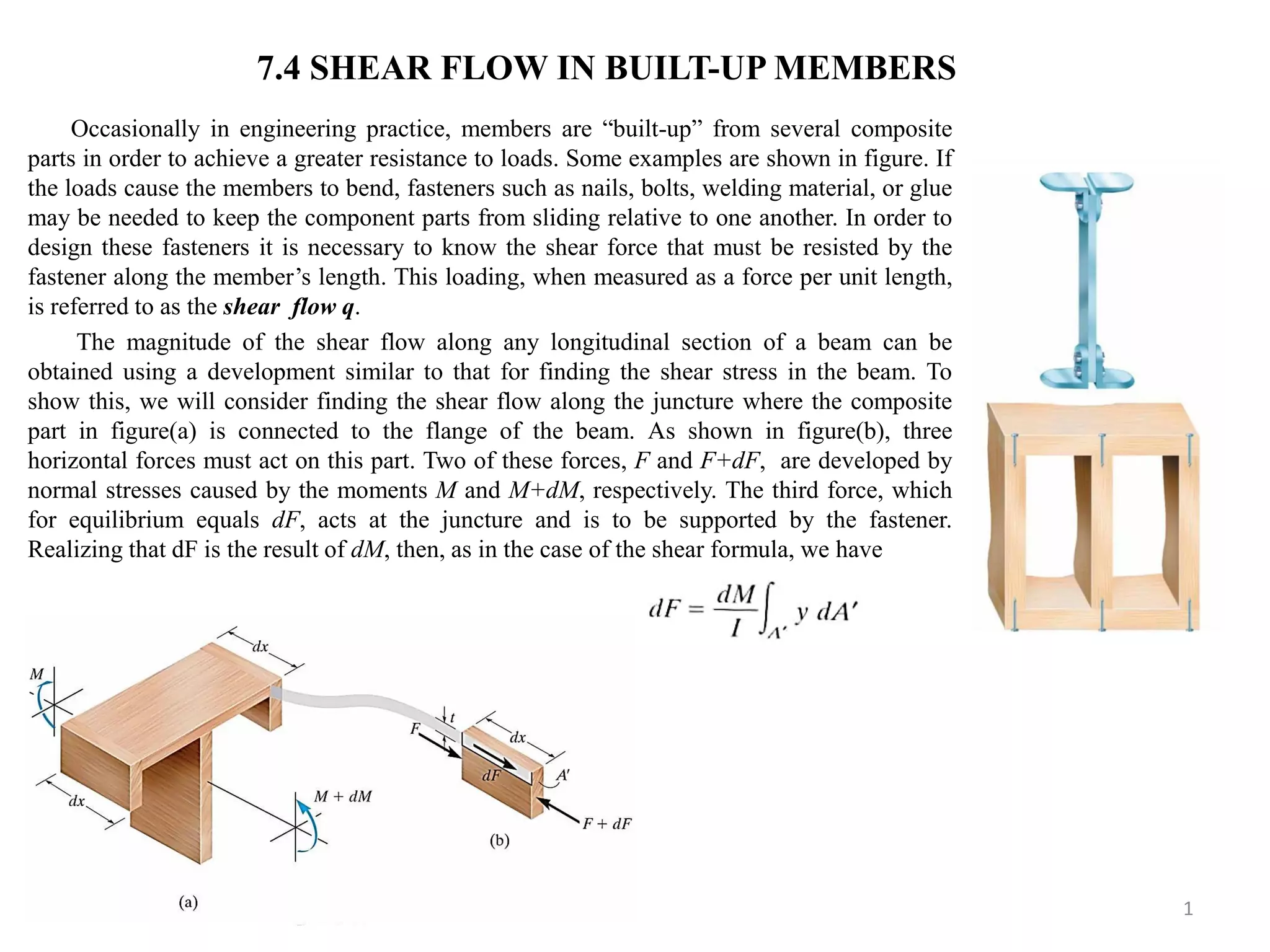
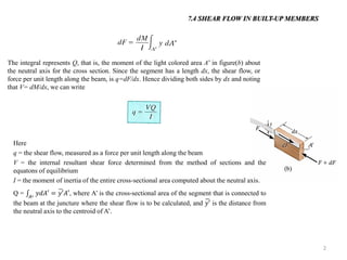
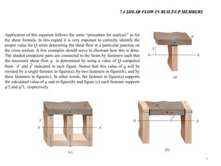
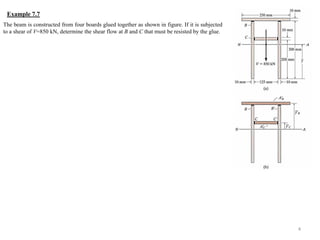
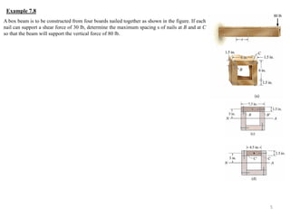
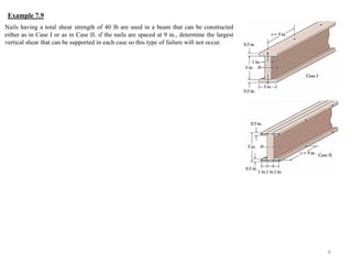
This document discusses shear flow in built-up members, which are structural members constructed from composite parts joined together. It provides a formula to calculate the shear flow along the junction between composite parts based on the internal shear force, moment of inertia, and moment of a segment's area about the neutral axis. Examples are given to demonstrate calculating shear flow at specific points that must be resisted by fasteners joining the composite parts.
This book is intended to cover the basic Strength of Materials of the first
two years of an engineering degree or diploma course ; it does not attempt
to deal with the more specialized topics which usually comprise the final
year of such courses.
The work has been confined to the mathematical aspect of the subject
and no descriptive matter relating to design or materials testing has been
included.
it contains the basic information about the shear force diagram which is the part of the Mechanics of solid. there many numerical solved and whivh will give you detaild idea in S.f.d.
This Presentation presents the design of Rivet joints which are also called boiler joints. It contains various parameters upon which boiler joints are designed. Pls find and enjoy.
Young's modulus by single cantilever methodPraveen Vaidya
Young's modulus is a method to find the elasticity of a given solid material. The present article gives the explanation how to perform the experiment to determine the young's modulus by the use of material in the form of cantilever. The single cantilever method is used here.
STABILITY OF SLOPESSEEPAGE CONTROL MEASURES AND SLOPE PROTECTION
a finite slope AB, the stability of which is to be analyzed.
The method Consists of assuming a number of trial slip circles, and finding the factor of safety of each.
The circle corresponding to the minimum factor of safely is the critical slip circle.
Let AD be a trial slip circle, with r as the radius and O as the centre of rotation
Let W be the weight of the soil of the wedge ABDA of unit thickness, acting through the centroid G.
The driving moment MD will be equal to W x, where x, is the distance of line of action of W from the vertical line passing through the centre of rotation O.
if cu is the unit cohesion, and l is the length of the slip arc AD, the shear resistance developed along the slip surface will be equal to cu • l, which act at a radial distance r from centre of rotation O.
When slip is imminent in a cohesive soil, a tension crack will always DevelOP by the top surface of the slope along which no shear resistance can develop,
The depth of tension crack is given by
The effect of tension crack is to shorten the arc length along which shear resistance gets mobilised to AB' and to reduce the angle δ to δ'.
The length of the slip arc to be taken in the computation of resisting force is only AB', since tension crack break the continuity at B'.
The weight of the sliding wedge is weight of the area bounded by the ground surface, slip circle arc AB' and the tension crack.
IJRET : International Journal of Research in Engineering and Technology is an international peer reviewed, online journal published by eSAT Publishing House for the enhancement of research in various disciplines of Engineering and Technology. The aim and scope of the journal is to provide an academic medium and an important reference for the advancement and dissemination of research results that support high-level learning, teaching and research in the fields of Engineering and Technology. We bring together Scientists, Academician, Field Engineers, Scholars and Students of related fields of Engineering and Technology.
CFD Simulation of By-pass Flow in a HRSG module by R&R Consult.pptxR&R Consult
CFD analysis is incredibly effective at solving mysteries and improving the performance of complex systems!
Here's a great example: At a large natural gas-fired power plant, where they use waste heat to generate steam and energy, they were puzzled that their boiler wasn't producing as much steam as expected.
R&R and Tetra Engineering Group Inc. were asked to solve the issue with reduced steam production.
An inspection had shown that a significant amount of hot flue gas was bypassing the boiler tubes, where the heat was supposed to be transferred.
R&R Consult conducted a CFD analysis, which revealed that 6.3% of the flue gas was bypassing the boiler tubes without transferring heat. The analysis also showed that the flue gas was instead being directed along the sides of the boiler and between the modules that were supposed to capture the heat. This was the cause of the reduced performance.
Based on our results, Tetra Engineering installed covering plates to reduce the bypass flow. This improved the boiler's performance and increased electricity production.
It is always satisfying when we can help solve complex challenges like this. Do your systems also need a check-up or optimization? Give us a call!
Work done in cooperation with James Malloy and David Moelling from Tetra Engineering.
More examples of our work https://www.r-r-consult.dk/en/cases-en/
Hybrid optimization of pumped hydro system and solar- Engr. Abdul-Azeez.pdffxintegritypublishin
Advancements in technology unveil a myriad of electrical and electronic breakthroughs geared towards efficiently harnessing limited resources to meet human energy demands. The optimization of hybrid solar PV panels and pumped hydro energy supply systems plays a pivotal role in utilizing natural resources effectively. This initiative not only benefits humanity but also fosters environmental sustainability. The study investigated the design optimization of these hybrid systems, focusing on understanding solar radiation patterns, identifying geographical influences on solar radiation, formulating a mathematical model for system optimization, and determining the optimal configuration of PV panels and pumped hydro storage. Through a comparative analysis approach and eight weeks of data collection, the study addressed key research questions related to solar radiation patterns and optimal system design. The findings highlighted regions with heightened solar radiation levels, showcasing substantial potential for power generation and emphasizing the system's efficiency. Optimizing system design significantly boosted power generation, promoted renewable energy utilization, and enhanced energy storage capacity. The study underscored the benefits of optimizing hybrid solar PV panels and pumped hydro energy supply systems for sustainable energy usage. Optimizing the design of solar PV panels and pumped hydro energy supply systems as examined across diverse climatic conditions in a developing country, not only enhances power generation but also improves the integration of renewable energy sources and boosts energy storage capacities, particularly beneficial for less economically prosperous regions. Additionally, the study provides valuable insights for advancing energy research in economically viable areas. Recommendations included conducting site-specific assessments, utilizing advanced modeling tools, implementing regular maintenance protocols, and enhancing communication among system components.
Courier management system project report.pdfKamal Acharya
It is now-a-days very important for the people to send or receive articles like imported furniture, electronic items, gifts, business goods and the like. People depend vastly on different transport systems which mostly use the manual way of receiving and delivering the articles. There is no way to track the articles till they are received and there is no way to let the customer know what happened in transit, once he booked some articles. In such a situation, we need a system which completely computerizes the cargo activities including time to time tracking of the articles sent. This need is fulfilled by Courier Management System software which is online software for the cargo management people that enables them to receive the goods from a source and send them to a required destination and track their status from time to time.
Cosmetic shop management system project report.pdfKamal Acharya
Buying new cosmetic products is difficult. It can even be scary for those who have sensitive skin and are prone to skin trouble. The information needed to alleviate this problem is on the back of each product, but it's thought to interpret those ingredient lists unless you have a background in chemistry.
Instead of buying and hoping for the best, we can use data science to help us predict which products may be good fits for us. It includes various function programs to do the above mentioned tasks.
Data file handling has been effectively used in the program.
The automated cosmetic shop management system should deal with the automation of general workflow and administration process of the shop. The main processes of the system focus on customer's request where the system is able to search the most appropriate products and deliver it to the customers. It should help the employees to quickly identify the list of cosmetic product that have reached the minimum quantity and also keep a track of expired date for each cosmetic product. It should help the employees to find the rack number in which the product is placed.It is also Faster and more efficient way.
Industrial Training at Shahjalal Fertilizer Company Limited (SFCL)MdTanvirMahtab2
This presentation is about the working procedure of Shahjalal Fertilizer Company Limited (SFCL). A Govt. owned Company of Bangladesh Chemical Industries Corporation under Ministry of Industries.
About
Indigenized remote control interface card suitable for MAFI system CCR equipment. Compatible for IDM8000 CCR. Backplane mounted serial and TCP/Ethernet communication module for CCR remote access. IDM 8000 CCR remote control on serial and TCP protocol.
• Remote control: Parallel or serial interface.
• Compatible with MAFI CCR system.
• Compatible with IDM8000 CCR.
• Compatible with Backplane mount serial communication.
• Compatible with commercial and Defence aviation CCR system.
• Remote control system for accessing CCR and allied system over serial or TCP.
• Indigenized local Support/presence in India.
• Easy in configuration using DIP switches.
Technical Specifications
Indigenized remote control interface card suitable for MAFI system CCR equipment. Compatible for IDM8000 CCR. Backplane mounted serial and TCP/Ethernet communication module for CCR remote access. IDM 8000 CCR remote control on serial and TCP protocol.
Key Features
Indigenized remote control interface card suitable for MAFI system CCR equipment. Compatible for IDM8000 CCR. Backplane mounted serial and TCP/Ethernet communication module for CCR remote access. IDM 8000 CCR remote control on serial and TCP protocol.
• Remote control: Parallel or serial interface
• Compatible with MAFI CCR system
• Copatiable with IDM8000 CCR
• Compatible with Backplane mount serial communication.
• Compatible with commercial and Defence aviation CCR system.
• Remote control system for accessing CCR and allied system over serial or TCP.
• Indigenized local Support/presence in India.
Application
• Remote control: Parallel or serial interface.
• Compatible with MAFI CCR system.
• Compatible with IDM8000 CCR.
• Compatible with Backplane mount serial communication.
• Compatible with commercial and Defence aviation CCR system.
• Remote control system for accessing CCR and allied system over serial or TCP.
• Indigenized local Support/presence in India.
• Easy in configuration using DIP switches.
Event Management System Vb Net Project Report.pdfKamal Acharya
In present era, the scopes of information technology growing with a very fast .We do not see any are untouched from this industry. The scope of information technology has become wider includes: Business and industry. Household Business, Communication, Education, Entertainment, Science, Medicine, Engineering, Distance Learning, Weather Forecasting. Carrier Searching and so on.
My project named “Event Management System” is software that store and maintained all events coordinated in college. It also helpful to print related reports. My project will help to record the events coordinated by faculties with their Name, Event subject, date & details in an efficient & effective ways.
In my system we have to make a system by which a user can record all events coordinated by a particular faculty. In our proposed system some more featured are added which differs it from the existing system such as security.
Halogenation process of chemical process industries
Mm210(7b)
1. Occasionally in engineering practice, members are “built-up” from several composite parts in order to achieve a greater resistance to loads. Some examples are shown in figure. If the loads cause the members to bend, fasteners such as nails, bolts, welding material, or glue may be needed to keep the component parts from sliding relative to one another. In order to design these fasteners it is necessary to know the shear force that must be resisted by the fastener along the member’s length. This loading, when measured as a force per unit length, is referred to as the shear flow q.
The magnitude of the shear flow along any longitudinal section of a beam can be obtained using a development similar to that for finding the shear stress in the beam. To show this, we will consider finding the shear flow along the juncture where the composite part in figure(a) is connected to the flange of the beam. As shown in figure(b), three horizontal forces must act on this part. Two of these forces, F and F+dF, are developed by normal stresses caused by the moments M and M+dM, respectively. The third force, which for equilibrium equals dF, acts at the juncture and is to be supported by the fastener. Realizing that dF is the result of dM, then, as in the case of the shear formula, we have
1
7.4 SHEAR FLOW IN BUILT-UP MEMBERS
2. 2
7.4 SHEAR FLOW IN BUILT-UP MEMBERS
The integral represents Q, that is, the moment of the light colored area A’ in figure(b) about the neutral axis for the cross section. Since the segment has a length dx, the shear flow, or force per unit length along the beam, is q=dF/dx. Hence dividing both sides by dx and noting that V= dM/dx, we can write
Here
q = the shear flow, measured as a force per unit length along the beam
V = the internal resultant shear force determined from the method of sections and the equatons of equilibrium
I = the moment of inertia of the entire cross-sectional area computed about the neutral axis.
Q = 푦푑퐴′퐴′=푦′ 퐴′, where A’ is the cross-sectional area of the segment that is connected to the beam at the juncture where the shear flow is to be calculated, and 푦′ is the distance from the neutral axis to the centroid of A’.
3. 3
7.4 SHEAR FLOW IN BUILT-UP MEMBERS
Application of this equation follows the same “procedure for analysis” as for the shear formula. In this regard it is very impotant to correctly identify the proper value for Q when determinig the shear flow at a particular junction on the cross section. A few examples should serve to illustrate how this is done. The shaded composite parts are connected to the beam by fasteners such that the necessary shear flow q is determined by using a value of Q computed from A’ and 푦′ indicated in each figure. Notice that this value of q will be resisted by a single fastener in figure(a), by two fasteners in figure(b), and by three fasteners in figure(c). In other words, the fastener in figure(a) supports the calculated value of q and in figure(b) and figure (c) each fastener supports q/2 and q/3, respectively.
4. The beam is constructed from four boards glued together as shown in figure. If it is subjected to a shear of V=850 kN, determine the shear flow at B and C that must be resisted by the glue.
4
Example 7.7
5. A box beam is to be constructed from four boards nailed together as shown in the figure. If each nail can support a shear force of 30 lb, determine the maximum spacing s of nails at B and at C so that the beam will support the vertical force of 80 lb.
5
Example 7.8
6. Nails having a total shear strength of 40 lb are used in a beam that can be constructed either as in Case I or as in Case II. ıf the nails are spaced at 9 in., determine the largest vertical shear that can be supported in each case so this type of failure will not occur.
6
Example 7.9