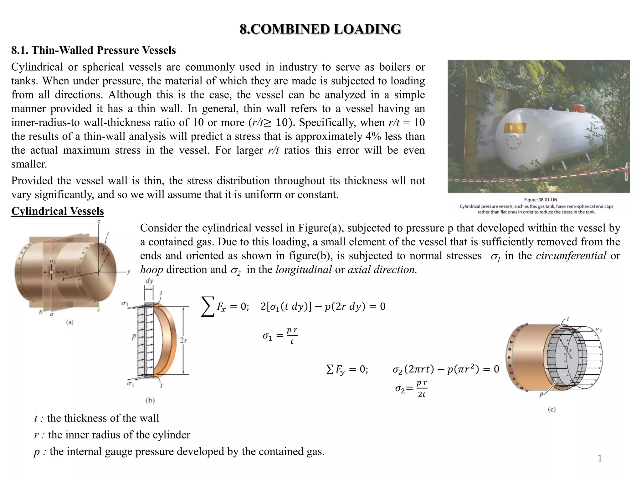
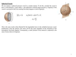
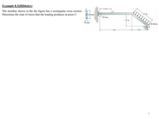
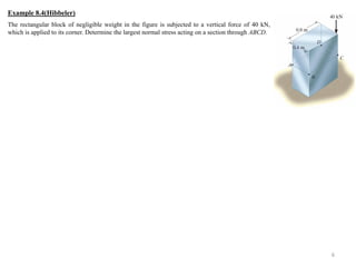
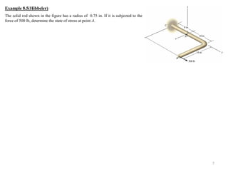
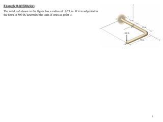
8.1. Thin-Walled Pressure Vessels 
Cylindrical or spherical vessels are commonly used in industry to serve as boilers or 
tanks. When under pressure, the material of which they are made is subjected to loading 
from all directions. Although this is the case, the vessel can be analyzed in a simple 
manner provided it has a thin wall. In general, thin wall refers to a vessel having an 
inner-radius-to wall-thickness ratio of 10 or more (r/t≥ 10). Specifically, when r/t = 10 
the results of a thin-wall analysis will predict a stress that is approximately 4% less than 
the actual maximum stress in the vessel. For larger r/t ratios this error will be even 
smaller. 
Provided the vessel wall is thin, the stress distribution throughout its thickness wll not 
vary significantly, and so we will assume that it is uniform or constant. 
Cylindrical Vessels 
1 
8.COMBINED LOADING 
Consider the cylindrical vessel in Figure(a), subjected to pressure p that developed within the vessel by 
a contained gas. Due to this loading, a small element of the vessel that is sufficiently removed from the 
ends and oriented as shown in figure(b), is subjected to normal stresses 1 in the circumferential or 
hoop direction and 2 in the longitudinal or axial direction. 
퐹푥 = 0; 2 휎1 푡 푑푦 − 푝 2푟 푑푦 = 0 
휎1 = 
푝 푟 
푡 
퐹푦 = 0; 휎2 2휋푟푡 − 푝 휋푟2 = 0 
휎2= 
푝 푟 
2푡 
t : the thickness of the wall 
r : the inner radius of the cylinder 
p : the internal gauge pressure developed by the contained gas.
We can analyze a spherical pressure vessel in a similar manner. To do this, consider the vessel to 
have a wall thickness t, inner radius r, and subjected to internal gauge pressure p, Figure(a). If the 
vessel is sectioned in half, the resulting free-body diagram is shown figure(b). 
This is the same result as that obtained for the longitudinal stress in the cylindrical pressure vessel. 
Furthermore, from the analysis, this stress will be the same regardless of the orientation of the 
hemispheric free-body diagram. Consequently, a small element of the material is subjected to the 
state of stress shown in Figure(a) 
2 
Spherical Vessels 
퐹푦 = 0; 휎2 2휋푟푡 − 푝 휋푟2 = 0 
휎2= 
푝 푟 
2푡
A cylindrical pressure vessel has an inner diameter of 1.2 m and a thickness of 12 mm. Determine the maximum internal pressure it can sustain so that neither its circumferential nor its longitudinal stress component exceeds 140 MPa. Under the same conditions, what is the maximum internal pressure that a similar-size spherical vessel can sustain? 
3 
Example 8.1(Hibbeler)
A force of 150 lb is applied to the edge of the member shown in the figure. Neglect the weight of the member and determine the state of stress at points B and C. 
4 
Example 8.2(hibbeler)
The member shown in the the figure has a rectangular cross section. Determine the state of stress that the loading produces at point C. 
5 
Example 8.3(Hibbeler)
The rectangular block of negligible weight in the figure is subjected to a vertical force of 40 kN, which is applied to its corner. Determine the largest normal stress acting on a section through ABCD. 
6 
Example 8.4(Hibbeler)
The solid rod shown in the figure has a radius of 0.75 in. If it is subjected to the force of 500 lb, determine the state of stress at point A. 
7 
Example 8.5(Hibbeler)
The solid rod shown in the figure has a radius of 0.75 in. If it is subjected to the force of 800 lb, determine the state of stress at point A. 
8 
Example 8.6(Hibbeler)

Mm210(8)

  • 1.
    8.1. Thin-Walled PressureVessels Cylindrical or spherical vessels are commonly used in industry to serve as boilers or tanks. When under pressure, the material of which they are made is subjected to loading from all directions. Although this is the case, the vessel can be analyzed in a simple manner provided it has a thin wall. In general, thin wall refers to a vessel having an inner-radius-to wall-thickness ratio of 10 or more (r/t≥ 10). Specifically, when r/t = 10 the results of a thin-wall analysis will predict a stress that is approximately 4% less than the actual maximum stress in the vessel. For larger r/t ratios this error will be even smaller. Provided the vessel wall is thin, the stress distribution throughout its thickness wll not vary significantly, and so we will assume that it is uniform or constant. Cylindrical Vessels 1 8.COMBINED LOADING Consider the cylindrical vessel in Figure(a), subjected to pressure p that developed within the vessel by a contained gas. Due to this loading, a small element of the vessel that is sufficiently removed from the ends and oriented as shown in figure(b), is subjected to normal stresses 1 in the circumferential or hoop direction and 2 in the longitudinal or axial direction. 퐹푥 = 0; 2 휎1 푡 푑푦 − 푝 2푟 푑푦 = 0 휎1 = 푝 푟 푡 퐹푦 = 0; 휎2 2휋푟푡 − 푝 휋푟2 = 0 휎2= 푝 푟 2푡 t : the thickness of the wall r : the inner radius of the cylinder p : the internal gauge pressure developed by the contained gas.
  • 2.
    We can analyzea spherical pressure vessel in a similar manner. To do this, consider the vessel to have a wall thickness t, inner radius r, and subjected to internal gauge pressure p, Figure(a). If the vessel is sectioned in half, the resulting free-body diagram is shown figure(b). This is the same result as that obtained for the longitudinal stress in the cylindrical pressure vessel. Furthermore, from the analysis, this stress will be the same regardless of the orientation of the hemispheric free-body diagram. Consequently, a small element of the material is subjected to the state of stress shown in Figure(a) 2 Spherical Vessels 퐹푦 = 0; 휎2 2휋푟푡 − 푝 휋푟2 = 0 휎2= 푝 푟 2푡
  • 3.
    A cylindrical pressurevessel has an inner diameter of 1.2 m and a thickness of 12 mm. Determine the maximum internal pressure it can sustain so that neither its circumferential nor its longitudinal stress component exceeds 140 MPa. Under the same conditions, what is the maximum internal pressure that a similar-size spherical vessel can sustain? 3 Example 8.1(Hibbeler)
  • 4.
    A force of150 lb is applied to the edge of the member shown in the figure. Neglect the weight of the member and determine the state of stress at points B and C. 4 Example 8.2(hibbeler)
  • 5.
    The member shownin the the figure has a rectangular cross section. Determine the state of stress that the loading produces at point C. 5 Example 8.3(Hibbeler)
  • 6.
    The rectangular blockof negligible weight in the figure is subjected to a vertical force of 40 kN, which is applied to its corner. Determine the largest normal stress acting on a section through ABCD. 6 Example 8.4(Hibbeler)
  • 7.
    The solid rodshown in the figure has a radius of 0.75 in. If it is subjected to the force of 500 lb, determine the state of stress at point A. 7 Example 8.5(Hibbeler)
  • 8.
    The solid rodshown in the figure has a radius of 0.75 in. If it is subjected to the force of 800 lb, determine the state of stress at point A. 8 Example 8.6(Hibbeler)