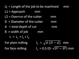
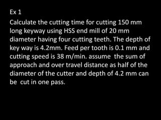
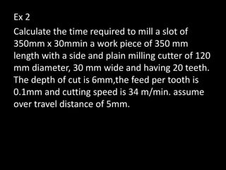
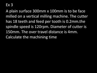
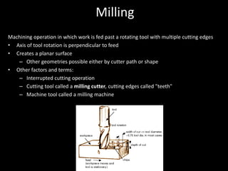
MANUFACTURING SYSTEMS
MILLING MACHINE
• Material is removed by means of a revolving
cutter
• These cutters have many teeth
• These cutters are known as milling cutters
• Each cutter has equally spaced peripheral
teeth
• Milling machines are used to produce flat and
curved shapes
MILLING MACHINE & FUNCTION
• Milling is the process of cutting material away by
feeding the work piece past a rotating multiple tooth
cutter.
• The cutter is rotating at a very high speed and because
of multiple cutting edges it removes metal at a very
high rate.
• The m/c can hold more than one cutter at a time.
• The table holding the work can move in three different
movements ie longitudinal, crosswise and vertical.
• These machines are used for production work and are
very useful for machining a variety of tool room work.
Classification of milling machines
• Column and knee type
– Hand milling machine
– Horizontal milling machine
– Vertical milling machine
– Universal milling machine
– Ominiversal milling machine
• Manufacturing of fixed bed type
– Simplex milling machine
– Duplex milling machine
– Triplex milling machine
Classification of milling machines
• Planer type
• Special types
– Rotary table milling machine
– Drum milling machine
– Planetary milling machine
HAND MILLING M/C
• This is the simplest of milling m/c.
• The feeding movement of the table is by
manual hand control.
• The m/c is relatively smaller in size compared
to other milling m/c.
• This m/c is suitable for light and simple milling
machine jobs.
HORIZONTAL MILLING MACHINE
• Difference from plain horizontal machine is
addition of table swivel housing
▪ Located between table and saddle
▪ Permits table to be swiveled 45° in either direction
in a horizontal plane
• Used for milling of helical grooves in twist
drills, milling cutters, and gears
Horizontal milling machine
VERTICAL MILLING MACHINE
• The position of spindle in this machine is in a
vertical or perpendicular to the work table.
• The spindle head which is clamped to the
vertical column may be swiveled to an angle
enabling the cutter to cut angular surfaces.
• End mills and face cutting cutter are the tools
mounted on the spindle.
• The machine is adopted for machining
grooves, slots and flat surfaces.
Vertical milling machine
UNIVERSAL MILLING M/C
• The table of universal milling machine is mounted on
a circular swiveling base which can be swiveled to
any angle up to 45° on either side of the normal
position.
• This has the additional movement of the table where
job can be fed at an angle to the machine.
• The universal movement (45°) helps in helical milling
operation.
• Special attachment such as dividing head, rotary and
slotting attachment may be fitted on the machine.
• The machine can produce various types of gears,
twist drill and reamers
Universal milling machine
OMNIVERSAL MILLING MACHINE
• The table can be tilted in a vertical plane by
providing a swivel arrangement at the knee.
• This additional arrangement enables machine
taper spiral groves in reamers, bevel gear.
• All other aspects are same as in universal
milling machine.
Ominiversal milling machine
Simplex and duplex milling
Drum type milling machine
Principle of milling
• Up milling
• Down milling
Up milling
• At start
– Zero depth of cut
– Zero chip thickness
– Less shock load
Down milling
• Lower clamping force
• Good surface finish
• Good dimensional accuracy
PARTS OF MILLING MACHINE
• Base
• Column
• Knee
• Saddle
• Table
• Spindle
PARTS OF MILLING MACHINE
Specification of milling machine
• Width of the table
• Length of the table
• Max distance the knee can travel
• Max longitudinal movement
• Max cross feed
• Number of spindle speeds
• Power of main drive motor
Type of milling cutters
• Plain milling cutters
• Side milling cutters
• End milling cutters
• Face milling cutters
• Metal slitting cutter
• Angle milling cutters
• Formed milling cutters
• Wood ruff-key milling cutters
• T-slot milling cutters
• Fly cutter
Plain milling cutters
Light duty
Standard shank type
High helix cutter
Heavy duty
Side milling cutters
End milling cutter
Face milling cutter
Metal-Slitting cutter
Angle milling cutter
Types of Formed Cutters
Concave Convex Gear Tooth
Wood ruff-key milling cutter
T-slot cutter
Fly cutter
Dove-tail cutter
MILLING MACHINE CUTTER OPERATION
• Plain milling
• Face milling
• Side milling
• Straddle milling
• Angular milling
• Gang milling
• Form milling
• Saw milling
• Gear milling
• Helical milling
Selection of cutting speed
• The properties of material being cut
• Diameter and life of cutter
• Number of cutter teeth
• Feed
• Depth of cut and width of cut
• Use of coolant
Cutting speed, Feed and Depth of cut
Vc cutting speed (peripheral speed of the cutter)
D - Diameter of the cutter mm
N - Cutter speed rpm
Vc =
πDN
1000
Feed ( f )
• Feed can be expressed in three methods
– Feed per tooth mm/tooth
– Feed per revolution mm/revolution
– Feed per minute mm/min
Feed per min (ø) = feed/rev x cutter speed (rpm)
Or
f = ft x Z x N
Ft - feed rate/tooth
Z - No of teeth on the cutter periphery
Depth of cut (d)
• Thickness of the layer of material removed in
one pass of the workpiece
MRR
B = width of cut
d = depth of cut
f = rate of feed
MRR = B x d x f mm3/min
Machining time
Machining time =
tm =
Length of cut
Feed rate
L
ft x Z x N
Lj = Length of the job to be machined mm
L1 = Approach mm
L2 = Overrun of the cutter mm
D = Diameter of the cutter mm
d = total depth of cut mm
B = width of job mm
L = Lj + l1 + l2
For plain milling l1 = 𝑑 (𝐷 − 𝑑) mm
For face milling l1 = 0.5 (D- 𝐷2 − 𝐵2) mm
Ex 1
Calculate the cutting time for cutting 150 mm
long keyway using HSS end mill of 20 mm
diameter having four cutting teeth. The depth of
key way is 4.2mm. Feed per tooth is 0.1 mm and
cutting speed is 38 m/min. assume the sum of
approach and over travel distance as half of the
diameter of the cutter and depth of 4.2 mm can
be cut in one pass.
Ex 2
Calculate the time required to mill a slot of
350mm x 30mmin a work piece of 350 mm
length with a side and plain milling cutter of 120
mm diameter, 30 mm wide and having 20 teeth.
The depth of cut is 6mm,the feed per tooth is
0.1mm and cutting speed is 34 m/min. assume
over travel distance of 5mm.
Ex 3
A plain surface 300mm x 100mm is to be face
milled on a vertical milling machine. The cutter
has 18 teeth and feed per tooth is 0.2mm.the
spindle speed is 120rpm. Diameter of cutter is
150mm. The over travel distance is 4mm.
Calculate the machining time
Dividing or indexing head
• One of most important attachments for milling
machine
• Used to divide circumference of workpiece into
equally spaced divisions when milling gears,
splines, squares and hexagons
• Also used to rotate workpiece at predetermined
ratio to table feed rate
• Permits cutting of bolt heads, gear teeth, ratchets
• Revolve work as required to cut helical gears and
flutes in drills, reamers, and other tools
– When connected to lead screw of milling machine
Type of dividing head
• Plain dividing head
• Universal dividing head
• Optical dividing head
Indexing plate holes
Plate no 1 : 15, 16, 17, 18, 19, 20
Plate no 2 : 21, 23, 27, 29, 31, 33
Plate no 3 : 37, 39, 41, 43, 47, 49
Method of indexing
• Rapid or direct indexing
• Simple or plain indexing
• Compound indexing
• Differential indexing
• Angular indexing
Rapid or direct indexing
• The Simplest method of indexing
• This method is used only that work required a
small no of divisions
• Eg squre or hexagonal nut
• Plate connected to the spindle directly
• If the index plate has 24 holes
– Work piece can be divided into 2, 3, 4, 6, 8, 12, 24
➢ No of holes to move
No of holes on the plate
=
Ndiv
Simple and plain indexing
• Indexing plate is connected with the worm
• Plain indexing is used when it is required to
divide a circle into more no of parts
• No of crank rotations ncr =
ncr = 40
Ndiv
Compound indexing
• Compound indexing method is used when the
no of divisions required outside the range that
can be obtained by simple indexing
• Compound indexing is achieved in two stages
by using two hole circles of one index plate
Compound indexing procedure
• Check crank moment for each indexing
ncr =
• Write Ndiv (87) above and 40 below a straight
line
87
40
40
Ndiv
• Then factorize them
87 = 29 x 3
40 = 2 x 2 x 2 x 5
• Select two no representing two hole circles in
the same plate
• Let 29 and 33
• Write those no below 40 and factorize them
87 = 29 x 3
40 = 2 x 2 x 2 x 5
29 = 29 x 1
33 = 11 x 3
• Write the difference of those two no above
the Ndiv and factorize it (33 – 29 = 4)
4 = 2 x 2
87 = 29 x 3
40 = 2 x 2 x 2 x 5
29 = 29 x 1 (Nh1)
33 = 11 x 3 (Nh2)
• Now;
• Then check whole factors are in above the line
are canceled out with lower or not
• If they are canceled your selected hole circles
are correct
Factors of div required x factors of difference of hole circles
Factors of 40 x factors of 1st hole circle x factors of 2nd hole circle
(29 x 3) x (2 x 2)
(2 x 2 x 2 x 5) x (29 x 1) x (11 x 3)
• Now; Let nh1 to be the indexed in Nh1 and nh2 to
be indexed in Nh2
• Then ;
• Now find the nh1 and nh2 by trial and error
method
• Total index = nh1 holes in Nh1 hole circle ± nh2
holes in Nh2 hole circle by rotating the crank and
indexing plate together
nh1
Nh1 Nh2
nh2
Ndiv
40
=
±
MILLING MACHINE & FUNCTION
• Milling is the process of cutting material away by feeding
the work piece past a rotating multiple tooth cutter.
• The cutter is rotating at a very high speed and because of
multiple cutting edges it removes metal at a very high rate.
• The m/c can hold more than one cutter at a time.
• The table holding the work can move in three different
movements ie longitudinal, crosswise and vertical.
• These machines are used for production work and are very
useful for machining a variety of tool room work.
APPLICATION
• One or several milling cutters may be mounted on the
arbor at the same time.
• Multiple cutters increases the speed of cutting several
surfaces may also be machined simultaneously.
• The milling machine cutter is used for matching a
single part or for mass producing a number of
interchangeable parts.
TYPES OF MILLING MACHINE
• Hand milling m/c
• Plain milling m/c
• Universal milling m/c
• Omniversal milling m/c
• Vertical milling m/c
• Horizontal milling m/c
• This is the simplest of milling m/c.
• The feeding movement of the table is by manual hand
control.
• The m/c is relatively smaller in size compared to other
milling m/c.
• This m/c is suitable for light and simple milling machine
jobs.
HAND MILLING M/C
PLAIN MILLING MACHINE
• This machine is more rigid and sturdier than hand
milling machine.
• Table movement may be fed both by hand and by
power.
• Heavier work can be accommodated in this machine
for milling work.
• Rate of production is fast and is utilised for general
purpose production work.
UNIVERSAL MILLING M/C
• The table of universal milling machine is mounted on a
circular swiveling base which can be swiveled to any
angle up to on either side of the normal position.
• This has the additional movement of the table where
job can be fed at an angle to the machine.
• The universal movement (45°) helps in helical milling
operation.
• Special attachment such as dividing head, rotary and
slotting attachment may be fitted on the machine.
• The machine can produce various types of gears, twist
drill and reamers
OMNIVERSAL MILLING MACHINE
• Apart from having all the movements of a universal
milling machine, the table can be tilted in a vertical
plane by providing a swivel arrangement at the knee.
• This additional arrangement enables machine taper
spiral groves in reamers, bevel gear.
• All other aspects are same as in universal milling
machine.
VERTICAL MILLING MACHINE
• The position of spindle in this machine is in a vertical or
perpendicular to the work table.
• The spindle head which is clamped to the vertical column
may be swiveled to an angle enabling the cutter to cut
angular surfaces.
• End mills and face cutting cutter are the tools mounted on
the spindle.
• The machine is adopted for machining grooves, slots and flat
surfaces.
• Difference from plain horizontal machine is
addition of table swivel housing
– Located between table and saddle
– Permits table to be swiveled 45º in either
direction in a horizontal plane
• Used for milling of helical grooves in twist
drills, milling cutters, and gears
HORIZONTAL MILLING MACHINE
INDEXING
Indexing is the operation of dividing the periphery of
a piece of work into any number of equal parts eg
• Producing hex & sq headed bolts.
• Cutting splints on shafts.
• Cutting flutes on drill, tapes & reamers.
• Formation of teeth’s on spur gears.
DIVIDING HEAD
The attachment or the device used for
indexing is known as dividing head.
INDEXING METHODS
Direct or rapid indexing
• Used to divide the work into equal div of
2,3,4,6,8,12 & 24.
• Indexing plate has 24 holes.
• No of holes to be moved = 24/N
where N = no of division required.
Copyright © The McGraw-Hill Companies, Inc. Permission required for reproduction or display.
A – large index
plate
B - crank
C – small in
plate
D - crank
G – gear housing
Milling Cutters
Milling Cutter Materials
• Cutter Characteristics
– Harder than metal being machined
– Strong enough to withstand cutting
pressures
– Tough to resist shock resulting from
contact
– Resist heat and abrasion of cutting
– Available in various sizes and shapes
High-Speed Steel
• Iron with additives
– Carbon: hardening agent
– Tungsten and Molybdenum: enable steel to
retain hardness up to red heat
– Chromium: increases toughness and wear
resistance
– Vanadium: increases tensile strength
• Used for most solid milling cutters
Cemented-Carbide
• Higher rates of production (3-10 times
faster)
• Must select proper type of carbide
– Straight tungsten carbide: cast iron, plastics
– Tantalum carbide: low/medium-carbon steel
– Tungsten-titanium carbide: high-carbon steel
Metal-Slitting Saws
• Basically thin plain milling cutters with sides
relieved or "dished" to prevent rubbing or
binding when used
• Widths from 1/32 to 3/16 in.
• Operated at approximately 1/4 to 1/8 of
feed per tooth used for other cutters
• Not advisable to key saw to milling arbor
• Backlash eliminator should be engaged
Milling operations
• Plain or slab milling
• Face milling
• Anguar milling
• Form milling
• Straddle milling
• Gang milling
• End milling
• T-slot milling
• Dove-tail milling
• Saw milling
• Involute gear cutting
Advantages of Climb Milling
• Increased tool life (up to 50%)
– Chips pile up behind or to left of cutter
• Less costly fixtures required
– Forces workpiece down so simpler holding
devices required
• Improved surface finishes
– Chips less likely to be carried into workpiece
Advantages of Climb Milling
• Less edge breakout
– Thickness of chip tends to get smaller as nears
edge of workpiece, less chance of breaking
• Easier chip removal
– Chips fall behind cutter
• Lower power requirements
– Cutter with higher rake angle can be used so
approximately 20% less power required
Disadvantages of Climb Milling
• Method cannot be used unless machine has
backlash eliminator and table gibs tightened
• Cannot be used for machining castings or
hot-rolled steel
– Hard outer scale will damage cutter
Milling
Machining operation in which work is fed past a rotating tool with multiple cutting edges
• Axis of tool rotation is perpendicular to feed
• Creates a planar surface
– Other geometries possible either by cutter path or shape
• Other factors and terms:
– Interrupted cutting operation
– Cutting tool called a milling cutter, cutting edges called "teeth"
– Machine tool called a milling machine
(a) peripheral milling
(b) face milling.
Two Forms of Milling
Peripheral Milling vs. Face Milling
• Peripheral milling
– Cutter axis parallel to surface being machined
– Cutting edges on outside periphery of cutter
• Face milling
– Cutter axis perpendicular to surface being milled
– Cutting edges on both the end and outside periphery of the cutter
• Basic form of peripheral milling in which the
cutter width extends beyond the workpiece on
both sides
Slab Milling
• Width of cutter is less than workpiece width,
creating a slot in the work
Slotting
Cutter overhangs
work on both sides
Conventional Face Milling
High speed face
milling using
indexable inserts
• Cutter diameter is
less than work
width, so a slot is
cut into part
End Milling
Form of end milling
in which the
outside periphery
of a flat part is
cut
Profile Milling
• Another form
of end milling
used to mill
shallow
pockets into
flat parts
Pocket Milling
• Ball-nose cutter
fed back and forth
across work along
a curvilinear path
at close intervals
to create a three
dimensional
surface form
Surface Contouring

Manufacturing systems milling operation.pdf

  • 1.
  • 2.
    • Material isremoved by means of a revolving cutter • These cutters have many teeth • These cutters are known as milling cutters • Each cutter has equally spaced peripheral teeth • Milling machines are used to produce flat and curved shapes
  • 3.
    MILLING MACHINE &FUNCTION • Milling is the process of cutting material away by feeding the work piece past a rotating multiple tooth cutter. • The cutter is rotating at a very high speed and because of multiple cutting edges it removes metal at a very high rate. • The m/c can hold more than one cutter at a time. • The table holding the work can move in three different movements ie longitudinal, crosswise and vertical. • These machines are used for production work and are very useful for machining a variety of tool room work.
  • 4.
    Classification of millingmachines • Column and knee type – Hand milling machine – Horizontal milling machine – Vertical milling machine – Universal milling machine – Ominiversal milling machine • Manufacturing of fixed bed type – Simplex milling machine – Duplex milling machine – Triplex milling machine
  • 5.
    Classification of millingmachines • Planer type • Special types – Rotary table milling machine – Drum milling machine – Planetary milling machine
  • 6.
    HAND MILLING M/C •This is the simplest of milling m/c. • The feeding movement of the table is by manual hand control. • The m/c is relatively smaller in size compared to other milling m/c. • This m/c is suitable for light and simple milling machine jobs.
  • 8.
    HORIZONTAL MILLING MACHINE •Difference from plain horizontal machine is addition of table swivel housing ▪ Located between table and saddle ▪ Permits table to be swiveled 45° in either direction in a horizontal plane • Used for milling of helical grooves in twist drills, milling cutters, and gears
  • 9.
  • 10.
    VERTICAL MILLING MACHINE •The position of spindle in this machine is in a vertical or perpendicular to the work table. • The spindle head which is clamped to the vertical column may be swiveled to an angle enabling the cutter to cut angular surfaces. • End mills and face cutting cutter are the tools mounted on the spindle. • The machine is adopted for machining grooves, slots and flat surfaces.
  • 11.
  • 12.
    UNIVERSAL MILLING M/C •The table of universal milling machine is mounted on a circular swiveling base which can be swiveled to any angle up to 45° on either side of the normal position. • This has the additional movement of the table where job can be fed at an angle to the machine. • The universal movement (45°) helps in helical milling operation. • Special attachment such as dividing head, rotary and slotting attachment may be fitted on the machine. • The machine can produce various types of gears, twist drill and reamers
  • 13.
  • 14.
    OMNIVERSAL MILLING MACHINE •The table can be tilted in a vertical plane by providing a swivel arrangement at the knee. • This additional arrangement enables machine taper spiral groves in reamers, bevel gear. • All other aspects are same as in universal milling machine.
  • 15.
  • 16.
  • 17.
  • 18.
    Principle of milling •Up milling • Down milling
  • 19.
    Up milling • Atstart – Zero depth of cut – Zero chip thickness – Less shock load
  • 20.
    Down milling • Lowerclamping force • Good surface finish • Good dimensional accuracy
  • 21.
    PARTS OF MILLINGMACHINE • Base • Column • Knee • Saddle • Table • Spindle
  • 22.
  • 24.
    Specification of millingmachine • Width of the table • Length of the table • Max distance the knee can travel • Max longitudinal movement • Max cross feed • Number of spindle speeds • Power of main drive motor
  • 25.
    Type of millingcutters • Plain milling cutters • Side milling cutters • End milling cutters • Face milling cutters • Metal slitting cutter • Angle milling cutters • Formed milling cutters • Wood ruff-key milling cutters • T-slot milling cutters • Fly cutter
  • 26.
    Plain milling cutters Lightduty Standard shank type High helix cutter Heavy duty
  • 27.
  • 28.
  • 29.
  • 30.
  • 31.
  • 32.
    Types of FormedCutters Concave Convex Gear Tooth
  • 33.
  • 34.
  • 35.
  • 36.
  • 37.
    MILLING MACHINE CUTTEROPERATION • Plain milling • Face milling • Side milling • Straddle milling • Angular milling • Gang milling • Form milling • Saw milling • Gear milling • Helical milling
  • 44.
    Selection of cuttingspeed • The properties of material being cut • Diameter and life of cutter • Number of cutter teeth • Feed • Depth of cut and width of cut • Use of coolant
  • 45.
    Cutting speed, Feedand Depth of cut Vc cutting speed (peripheral speed of the cutter) D - Diameter of the cutter mm N - Cutter speed rpm Vc = πDN 1000
  • 46.
    Feed ( f) • Feed can be expressed in three methods – Feed per tooth mm/tooth – Feed per revolution mm/revolution – Feed per minute mm/min Feed per min (ø) = feed/rev x cutter speed (rpm) Or f = ft x Z x N Ft - feed rate/tooth Z - No of teeth on the cutter periphery
  • 47.
    Depth of cut(d) • Thickness of the layer of material removed in one pass of the workpiece
  • 48.
    MRR B = widthof cut d = depth of cut f = rate of feed MRR = B x d x f mm3/min
  • 49.
    Machining time Machining time= tm = Length of cut Feed rate L ft x Z x N
  • 50.
    Lj = Lengthof the job to be machined mm L1 = Approach mm L2 = Overrun of the cutter mm D = Diameter of the cutter mm d = total depth of cut mm B = width of job mm L = Lj + l1 + l2 For plain milling l1 = 𝑑 (𝐷 − 𝑑) mm For face milling l1 = 0.5 (D- 𝐷2 − 𝐵2) mm
  • 51.
    Ex 1 Calculate thecutting time for cutting 150 mm long keyway using HSS end mill of 20 mm diameter having four cutting teeth. The depth of key way is 4.2mm. Feed per tooth is 0.1 mm and cutting speed is 38 m/min. assume the sum of approach and over travel distance as half of the diameter of the cutter and depth of 4.2 mm can be cut in one pass.
  • 52.
    Ex 2 Calculate thetime required to mill a slot of 350mm x 30mmin a work piece of 350 mm length with a side and plain milling cutter of 120 mm diameter, 30 mm wide and having 20 teeth. The depth of cut is 6mm,the feed per tooth is 0.1mm and cutting speed is 34 m/min. assume over travel distance of 5mm.
  • 53.
    Ex 3 A plainsurface 300mm x 100mm is to be face milled on a vertical milling machine. The cutter has 18 teeth and feed per tooth is 0.2mm.the spindle speed is 120rpm. Diameter of cutter is 150mm. The over travel distance is 4mm. Calculate the machining time
  • 54.
    Dividing or indexinghead • One of most important attachments for milling machine • Used to divide circumference of workpiece into equally spaced divisions when milling gears, splines, squares and hexagons • Also used to rotate workpiece at predetermined ratio to table feed rate • Permits cutting of bolt heads, gear teeth, ratchets • Revolve work as required to cut helical gears and flutes in drills, reamers, and other tools – When connected to lead screw of milling machine
  • 56.
    Type of dividinghead • Plain dividing head • Universal dividing head • Optical dividing head
  • 63.
    Indexing plate holes Plateno 1 : 15, 16, 17, 18, 19, 20 Plate no 2 : 21, 23, 27, 29, 31, 33 Plate no 3 : 37, 39, 41, 43, 47, 49
  • 64.
    Method of indexing •Rapid or direct indexing • Simple or plain indexing • Compound indexing • Differential indexing • Angular indexing
  • 65.
    Rapid or directindexing • The Simplest method of indexing • This method is used only that work required a small no of divisions • Eg squre or hexagonal nut • Plate connected to the spindle directly • If the index plate has 24 holes – Work piece can be divided into 2, 3, 4, 6, 8, 12, 24 ➢ No of holes to move No of holes on the plate = Ndiv
  • 66.
    Simple and plainindexing • Indexing plate is connected with the worm • Plain indexing is used when it is required to divide a circle into more no of parts • No of crank rotations ncr = ncr = 40 Ndiv
  • 68.
    Compound indexing • Compoundindexing method is used when the no of divisions required outside the range that can be obtained by simple indexing • Compound indexing is achieved in two stages by using two hole circles of one index plate
  • 69.
    Compound indexing procedure •Check crank moment for each indexing ncr = • Write Ndiv (87) above and 40 below a straight line 87 40 40 Ndiv
  • 70.
    • Then factorizethem 87 = 29 x 3 40 = 2 x 2 x 2 x 5 • Select two no representing two hole circles in the same plate • Let 29 and 33 • Write those no below 40 and factorize them 87 = 29 x 3 40 = 2 x 2 x 2 x 5 29 = 29 x 1 33 = 11 x 3
  • 71.
    • Write thedifference of those two no above the Ndiv and factorize it (33 – 29 = 4) 4 = 2 x 2 87 = 29 x 3 40 = 2 x 2 x 2 x 5 29 = 29 x 1 (Nh1) 33 = 11 x 3 (Nh2)
  • 72.
    • Now; • Thencheck whole factors are in above the line are canceled out with lower or not • If they are canceled your selected hole circles are correct Factors of div required x factors of difference of hole circles Factors of 40 x factors of 1st hole circle x factors of 2nd hole circle (29 x 3) x (2 x 2) (2 x 2 x 2 x 5) x (29 x 1) x (11 x 3)
  • 73.
    • Now; Letnh1 to be the indexed in Nh1 and nh2 to be indexed in Nh2 • Then ; • Now find the nh1 and nh2 by trial and error method • Total index = nh1 holes in Nh1 hole circle ± nh2 holes in Nh2 hole circle by rotating the crank and indexing plate together nh1 Nh1 Nh2 nh2 Ndiv 40 = ±
  • 76.
    MILLING MACHINE &FUNCTION • Milling is the process of cutting material away by feeding the work piece past a rotating multiple tooth cutter. • The cutter is rotating at a very high speed and because of multiple cutting edges it removes metal at a very high rate. • The m/c can hold more than one cutter at a time. • The table holding the work can move in three different movements ie longitudinal, crosswise and vertical. • These machines are used for production work and are very useful for machining a variety of tool room work.
  • 77.
    APPLICATION • One orseveral milling cutters may be mounted on the arbor at the same time. • Multiple cutters increases the speed of cutting several surfaces may also be machined simultaneously. • The milling machine cutter is used for matching a single part or for mass producing a number of interchangeable parts.
  • 78.
    TYPES OF MILLINGMACHINE • Hand milling m/c • Plain milling m/c • Universal milling m/c • Omniversal milling m/c • Vertical milling m/c • Horizontal milling m/c
  • 79.
    • This isthe simplest of milling m/c. • The feeding movement of the table is by manual hand control. • The m/c is relatively smaller in size compared to other milling m/c. • This m/c is suitable for light and simple milling machine jobs. HAND MILLING M/C
  • 80.
    PLAIN MILLING MACHINE •This machine is more rigid and sturdier than hand milling machine. • Table movement may be fed both by hand and by power. • Heavier work can be accommodated in this machine for milling work. • Rate of production is fast and is utilised for general purpose production work.
  • 81.
    UNIVERSAL MILLING M/C •The table of universal milling machine is mounted on a circular swiveling base which can be swiveled to any angle up to on either side of the normal position. • This has the additional movement of the table where job can be fed at an angle to the machine. • The universal movement (45°) helps in helical milling operation. • Special attachment such as dividing head, rotary and slotting attachment may be fitted on the machine. • The machine can produce various types of gears, twist drill and reamers
  • 82.
    OMNIVERSAL MILLING MACHINE •Apart from having all the movements of a universal milling machine, the table can be tilted in a vertical plane by providing a swivel arrangement at the knee. • This additional arrangement enables machine taper spiral groves in reamers, bevel gear. • All other aspects are same as in universal milling machine.
  • 83.
    VERTICAL MILLING MACHINE •The position of spindle in this machine is in a vertical or perpendicular to the work table. • The spindle head which is clamped to the vertical column may be swiveled to an angle enabling the cutter to cut angular surfaces. • End mills and face cutting cutter are the tools mounted on the spindle. • The machine is adopted for machining grooves, slots and flat surfaces.
  • 86.
    • Difference fromplain horizontal machine is addition of table swivel housing – Located between table and saddle – Permits table to be swiveled 45º in either direction in a horizontal plane • Used for milling of helical grooves in twist drills, milling cutters, and gears HORIZONTAL MILLING MACHINE
  • 88.
    INDEXING Indexing is theoperation of dividing the periphery of a piece of work into any number of equal parts eg • Producing hex & sq headed bolts. • Cutting splints on shafts. • Cutting flutes on drill, tapes & reamers. • Formation of teeth’s on spur gears.
  • 89.
    DIVIDING HEAD The attachmentor the device used for indexing is known as dividing head.
  • 91.
    INDEXING METHODS Direct orrapid indexing • Used to divide the work into equal div of 2,3,4,6,8,12 & 24. • Indexing plate has 24 holes. • No of holes to be moved = 24/N where N = no of division required.
  • 92.
    Copyright © TheMcGraw-Hill Companies, Inc. Permission required for reproduction or display. A – large index plate B - crank C – small in plate D - crank G – gear housing
  • 93.
  • 94.
    Milling Cutter Materials •Cutter Characteristics – Harder than metal being machined – Strong enough to withstand cutting pressures – Tough to resist shock resulting from contact – Resist heat and abrasion of cutting – Available in various sizes and shapes
  • 95.
    High-Speed Steel • Ironwith additives – Carbon: hardening agent – Tungsten and Molybdenum: enable steel to retain hardness up to red heat – Chromium: increases toughness and wear resistance – Vanadium: increases tensile strength • Used for most solid milling cutters
  • 96.
    Cemented-Carbide • Higher ratesof production (3-10 times faster) • Must select proper type of carbide – Straight tungsten carbide: cast iron, plastics – Tantalum carbide: low/medium-carbon steel – Tungsten-titanium carbide: high-carbon steel
  • 97.
    Metal-Slitting Saws • Basicallythin plain milling cutters with sides relieved or "dished" to prevent rubbing or binding when used • Widths from 1/32 to 3/16 in. • Operated at approximately 1/4 to 1/8 of feed per tooth used for other cutters • Not advisable to key saw to milling arbor • Backlash eliminator should be engaged
  • 98.
    Milling operations • Plainor slab milling • Face milling • Anguar milling • Form milling • Straddle milling • Gang milling • End milling • T-slot milling • Dove-tail milling • Saw milling • Involute gear cutting
  • 101.
    Advantages of ClimbMilling • Increased tool life (up to 50%) – Chips pile up behind or to left of cutter • Less costly fixtures required – Forces workpiece down so simpler holding devices required • Improved surface finishes – Chips less likely to be carried into workpiece
  • 102.
    Advantages of ClimbMilling • Less edge breakout – Thickness of chip tends to get smaller as nears edge of workpiece, less chance of breaking • Easier chip removal – Chips fall behind cutter • Lower power requirements – Cutter with higher rake angle can be used so approximately 20% less power required
  • 103.
    Disadvantages of ClimbMilling • Method cannot be used unless machine has backlash eliminator and table gibs tightened • Cannot be used for machining castings or hot-rolled steel – Hard outer scale will damage cutter
  • 105.
    Milling Machining operation inwhich work is fed past a rotating tool with multiple cutting edges • Axis of tool rotation is perpendicular to feed • Creates a planar surface – Other geometries possible either by cutter path or shape • Other factors and terms: – Interrupted cutting operation – Cutting tool called a milling cutter, cutting edges called "teeth" – Machine tool called a milling machine
  • 106.
    (a) peripheral milling (b)face milling. Two Forms of Milling
  • 107.
    Peripheral Milling vs.Face Milling • Peripheral milling – Cutter axis parallel to surface being machined – Cutting edges on outside periphery of cutter • Face milling – Cutter axis perpendicular to surface being milled – Cutting edges on both the end and outside periphery of the cutter
  • 108.
    • Basic formof peripheral milling in which the cutter width extends beyond the workpiece on both sides Slab Milling
  • 109.
    • Width ofcutter is less than workpiece width, creating a slot in the work Slotting
  • 110.
    Cutter overhangs work onboth sides Conventional Face Milling
  • 111.
    High speed face millingusing indexable inserts
  • 112.
    • Cutter diameteris less than work width, so a slot is cut into part End Milling
  • 113.
    Form of endmilling in which the outside periphery of a flat part is cut Profile Milling
  • 114.
    • Another form ofend milling used to mill shallow pockets into flat parts Pocket Milling
  • 115.
    • Ball-nose cutter fedback and forth across work along a curvilinear path at close intervals to create a three dimensional surface form Surface Contouring