DIRECTIONAL COUPLER
  Parameters & Its Applications


             Submitted By:
             BRIJ VINOD    -090103063
             BHANU TEWARI - 090103064
             BHARAT AHUJA - 090103065
                                    1
DIRECTIONAL COUPLER
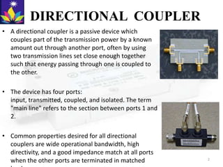
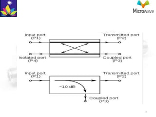
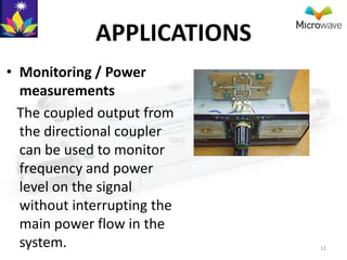
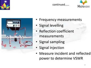
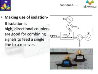
• A directional coupler is a passive device which
  couples part of the transmission power by a known
  amount out through another port, often by using
  two transmission lines set close enough together
  such that energy passing through one is coupled to
  the other.

• The device has four ports:
  input, transmitted, coupled, and isolated. The term
  "main line" refers to the section between ports 1 and
  2.

• Common properties desired for all directional
  couplers are wide operational bandwidth, high
  directivity, and a good impedance match at all ports
  when the other ports are terminated in matched          2
3
PARAMETERS:
Coupling factor:
• The coupling factor is defined as:


where P1 is the input power at port 1 and P3
 is the output power from the coupled
 port.

• The coupling factor represents the
  primary property of a directional coupler.

• Coupling is not constant, but varies with
  frequency.                                   4
continued……
• Directional couplers are specified in terms of the
  coupling accuracy at the frequency band center. For
  example, a 10 dB coupling ± 0.5 dB means that the
  directional coupler can have 9.5 dB to 10.5 dB
  coupling at the frequency band center.

• The accuracy is due to dimensional tolerances that
  can be held for the spacing of the two coupled lines.

• Another coupling specification is frequency
  sensitivity. A larger frequency sensitivity will allow a
  larger frequency band of operation.
                                                             5
Loss
The main line insertion loss from port 1 to port 2
  (P1 – P2) is:
• Insertion loss:

• Part of this loss is due to some power going to
  the coupled port and is called coupling loss and
  is given by-
• Coupling loss:


                                                     6
continued……
• The actual directional coupler loss will be a combination
  of coupling loss, dielectric loss, conductor loss, and VSWR
  loss. Depending on the frequency range, coupling loss
  becomes less significant above 15 dB coupling where the
  other losses constitute the majority of the total loss.


  A graph of the theoretical insertion loss (dB) vs coupling (dB) for   7
  adissipationless coupler is shown in Figure 2.
Isolation
• Isolation of a directional coupler can be defined as the
  difference in signal levels in dB between the input port
  and the isolated port when the two other ports are
  terminated by matched loads.

• Isolation:

• It can also be defined between the two output ports. In
  this case, one of the output ports is used as the input;
  the other is considered the output port while the other
  two ports (input and isolated) are terminated by
  matched loads.
                                                       8
continued……


• Consequently:

• The isolation between the input and the isolated ports
  may be different from the isolation between the two
  output ports.

• For example, the isolation between ports 1 and 4 can
  be 30 dB while the isolation between ports 2 and 3 can
  be a different value such as 25 dB. Isolation can be
  estimated from the coupling plus return loss.      9
Directivity
• Directivity is directly related to isolation.
  It is defined as:


 where: P3 is the output power from the
 coupled port and P4 is the power output
 from the isolated port.

• The directivity should be as high as
  possible. The directivity is very high at
  the design frequency and is a more
  sensitive function of frequency because it
  depends on the cancellation of two wave
                                          10
  components.
continued……

• Waveguide directional couplers will have the
  best directivity.

• Directivity is not directly measurable, and is
  calculated from the difference of the isolation
  and coupling measurements as:


                                                    11
APPLICATIONS
• Monitoring / Power
  measurements
  The coupled output from
  the directional coupler
  can be used to monitor
  frequency and power
  level on the signal
  without interrupting the
  main power flow in the
  system.                    12
continued……


• Frequency measurements
• Signal levelling
• Reflection coefficient
  measurements
• Signal sampling
• Signal injection
• Measure incident and reflected
  power to determine VSWR
                            13
continued……


• Making use of isolation-
  If isolation is
  high, directional couplers
  are good for combining
  signals to feed a single
  line to a receiver.


                                             14
15

Microwave- directional coupler paramets & applications

  • 1.
    DIRECTIONAL COUPLER Parameters & Its Applications Submitted By: BRIJ VINOD -090103063 BHANU TEWARI - 090103064 BHARAT AHUJA - 090103065 1
  • 2.
    DIRECTIONAL COUPLER • Adirectional coupler is a passive device which couples part of the transmission power by a known amount out through another port, often by using two transmission lines set close enough together such that energy passing through one is coupled to the other. • The device has four ports: input, transmitted, coupled, and isolated. The term "main line" refers to the section between ports 1 and 2. • Common properties desired for all directional couplers are wide operational bandwidth, high directivity, and a good impedance match at all ports when the other ports are terminated in matched 2
  • 3.
  • 4.
    PARAMETERS: Coupling factor: • Thecoupling factor is defined as: where P1 is the input power at port 1 and P3 is the output power from the coupled port. • The coupling factor represents the primary property of a directional coupler. • Coupling is not constant, but varies with frequency. 4
  • 5.
    continued…… • Directional couplersare specified in terms of the coupling accuracy at the frequency band center. For example, a 10 dB coupling ± 0.5 dB means that the directional coupler can have 9.5 dB to 10.5 dB coupling at the frequency band center. • The accuracy is due to dimensional tolerances that can be held for the spacing of the two coupled lines. • Another coupling specification is frequency sensitivity. A larger frequency sensitivity will allow a larger frequency band of operation. 5
  • 6.
    Loss The main lineinsertion loss from port 1 to port 2 (P1 – P2) is: • Insertion loss: • Part of this loss is due to some power going to the coupled port and is called coupling loss and is given by- • Coupling loss: 6
  • 7.
    continued…… • The actualdirectional coupler loss will be a combination of coupling loss, dielectric loss, conductor loss, and VSWR loss. Depending on the frequency range, coupling loss becomes less significant above 15 dB coupling where the other losses constitute the majority of the total loss. A graph of the theoretical insertion loss (dB) vs coupling (dB) for 7 adissipationless coupler is shown in Figure 2.
  • 8.
    Isolation • Isolation ofa directional coupler can be defined as the difference in signal levels in dB between the input port and the isolated port when the two other ports are terminated by matched loads. • Isolation: • It can also be defined between the two output ports. In this case, one of the output ports is used as the input; the other is considered the output port while the other two ports (input and isolated) are terminated by matched loads. 8
  • 9.
    continued…… • Consequently: • Theisolation between the input and the isolated ports may be different from the isolation between the two output ports. • For example, the isolation between ports 1 and 4 can be 30 dB while the isolation between ports 2 and 3 can be a different value such as 25 dB. Isolation can be estimated from the coupling plus return loss. 9
  • 10.
    Directivity • Directivity isdirectly related to isolation. It is defined as: where: P3 is the output power from the coupled port and P4 is the power output from the isolated port. • The directivity should be as high as possible. The directivity is very high at the design frequency and is a more sensitive function of frequency because it depends on the cancellation of two wave 10 components.
  • 11.
    continued…… • Waveguide directionalcouplers will have the best directivity. • Directivity is not directly measurable, and is calculated from the difference of the isolation and coupling measurements as: 11
  • 12.
    APPLICATIONS • Monitoring /Power measurements The coupled output from the directional coupler can be used to monitor frequency and power level on the signal without interrupting the main power flow in the system. 12
  • 13.
    continued…… • Frequency measurements •Signal levelling • Reflection coefficient measurements • Signal sampling • Signal injection • Measure incident and reflected power to determine VSWR 13
  • 14.
    continued…… • Making useof isolation- If isolation is high, directional couplers are good for combining signals to feed a single line to a receiver. 14
  • 15.