Downloaded 619 times


![Power transmission
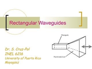
The average Poynting vector for the waveguide
fields is
where η = ηTE or ηTM depending on the mode
[ ] [ ]
z
EE
HEHEHE
yx
xyyxave
ˆ
2
Re
2
1
Re
2
1
22
***
η
+
=
−=×=P
∫ ∫∫ = =
+
=⋅=
a
x
b
y
yx
aveave dxdy
EE
dSP
0 0
22
2η
P
[W/m2
]
[W]](https://image.slidesharecdn.com/rectangularwaveguides-161102021049/85/Rectangular-waveguides-32-320.jpg)


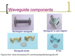
![Quality Factor, Q
Is defined as
( )
( ) ( )[ ]2233
22
101
2
TEmodedominantFor the
101
caaccab
abcca
QTE
+++
+
=
δ cof
where
σµπ
δ
101
1
=
LP
W
latione of oscily per cyclloss energ
storedge energyTime avera
πQ
π2
2
=
=](https://image.slidesharecdn.com/rectangularwaveguides-161102021049/85/Rectangular-waveguides-43-320.jpg)
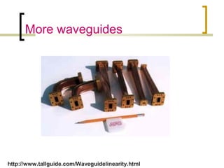
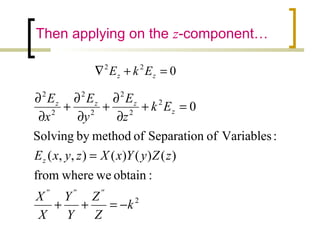
![Example
For a cavity of dimensions; 3cm x 2cm x 7cm filled with
air and made of copper (σc=5.8 x 10⁷
)
Find the resonant frequency and the quality factor
for the dominant mode.
Answer:
GHzfr 44.5
7
1
2
0
3
1
2
103
22210
=
+
+
⋅
=
6
9
106.1
)1044.5(
1 −
⋅=
⋅
=
coσµ
δ
( )
( ) ( )[ ] 378,568
73737322
72373
2233
22
101
=
+⋅++⋅
⋅⋅+
=
δ
TEQ
GHzfr 9
7
0
2
1
3
1
2
103
22210
110 =
+
+
⋅
=](https://image.slidesharecdn.com/rectangularwaveguides-161102021049/85/Rectangular-waveguides-44-320.jpg)

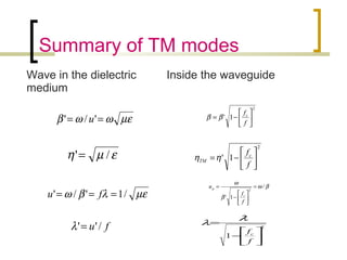
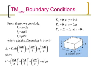
1) Rectangular waveguides can transmit electromagnetic waves above a certain cutoff frequency, acting as a high-pass filter. They support transverse electric (TE) and transverse magnetic (TM) modes of propagation. 2) For TM modes, the electric field is transverse to the direction of propagation, while the magnetic field has a longitudinal component. The modes are denoted TMmn, with m and n indicating the number of half-wavelength variations across the width and height. 3) For TE modes, the magnetic field is entirely transverse, while the electric field has a longitudinal component. These modes are denoted TEmn, with m and n having the same meaning as in the TM case.


![3_Antenna Array [Modlue 4] (1).pdf](https://cdn.slidesharecdn.com/ss_thumbnails/3antennaarraymodlue41-220419112111-thumbnail.jpg?width=640&height=640&fit=bounds)