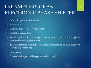
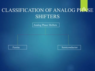
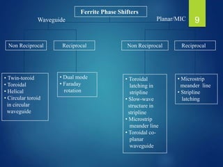
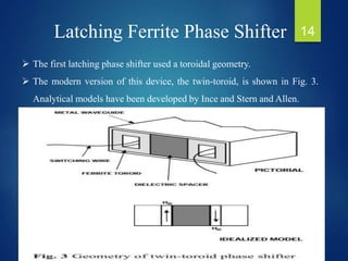
SlideShare a Scribd company logo
FERRITE PHASE SHIFTER
DEPARTMENT OF ELECTRONICS ENGINEERING
PONDICHERRY UNIVERSITY
SUBMITEED BY:
RIGVENDRA KUMAR VARDHAN
REG. NO.-14304022
M.TECH ECE 1ST YEAR
Contents
1. Ferrite
2. Phase Shifter.
3. Parameters Of An Electronic Phase Shifter
4. Classification
5. Ferrite Phase Shifters
6. Features
7. Latching Ferrite Phase Shifter
8. Dual Mode Ferrite Phase Shifter
9. Rotary Field Ferrite Phase Shifter
10. Applications.
11. Conclusion.
2
 Materials having electric anisotropy (tensor permittivity), and magnetic
anisotropy (tensor permeability). Some of the most practical anisotropic
materials for microwave applications are ferrimagnetic compounds, also
known as ferrites, such as yttrium iron garnet (YIG) and materials
composed of iron oxides and various other elements such as aluminium,
cobalt, manganese, and nickel.
 In contrast to ferromagnetic materials (e.g., iron, steel), ferrimagnetic
compounds have high resistivity and a significant amount of anisotropy at
microwave frequencies.
 The magnetic anisotropy of a ferrimagnetic material is actually induced by
applying a DC magnetic bias field. This field aligns the magnetic dipoles in
the ferrite material to produce a net (nonzero) magnetic dipole moment, and
causes the magnetic dipoles to precess at a frequency controlled by the
strength of the bias field.
FERRITE 3
 A microwave signal circularly polarized in the same direction as this
precession will interact strongly with the dipole moments, while an
oppositely polarized field will interact less strongly.
 Since, for a given direction of rotation, the sense of polarization changes
with the direction of propagation, a microwave signal will propagate
through a magnetically biased ferrite differently in different directions.
 This effect can be utilized to fabricate directional devices such as
isolators, circulators, and gyrators.
 Another useful characteristic of ferrimagnetic materials is that the
interaction with an applied microwave signal can be controlled by
adjusting the strength of the bias field. This effect leads to a variety of
control devices such as phase shifters, switches, and tunable resonators
and filters.
FERRITE 4
 A Phase Shifter is two-port device whose basic function is to provide a
change in the phase of RF signal with practically negligible attenuation.
 A phase shifter is a device which provides variable insertion phase in a
microwave signal path without altering the physical path length.
 Most phase shifters are two port devices characterized by low insertion
loss and low VSWR.
PHASE SHIFTER 5
6
PARAMETERS OF AN
ELECTRONIC PHASE SHIFTER
 Center frequency of operation
 Bandwidth
 Insertion loss (for 360° phase shift)
 VSWR or return loss
 Switching time (for digital operation) or time required for 360° phase
change (for analog operation)
 Switching power or energy (for digital operation) or dc holding power
(for analog operation)
 Phase error
 Power-handling capability(peak and average)
7
CLASSIFICATION OF ANALOG PHASE
SHIFTERS
Analog Phase Shifters
SemiconductorFerrite
8
Ferrite Phase Shifters
Non Reciprocal Reciprocal Non Reciprocal Reciprocal
• Twin-toroid
• Toroidal
• Helical
• Circular toroid
in circular
waveguide
• Toroidal
latching in
stripline
• Slow-wave
structure in
stripline
• Microstrip
meander line
• Toroidal co-
planar
waveguide
• Dual mode
• Faraday
rotation
• Microstrip
meander line
• Stripline
latching
Waveguide Planar/MIC 9
Semiconductor Phase
Shifters
Reciprocal Reciprocal Non reciprocalNon reciprocal
P-I-N
diode
GaAs FET
(Passive)
• Switched line
• Hybrid coupled
• Loaded line
• High-pass low-
pass
• Switched
network
GaAs FET
(active switch)
• Switched path
GaAs FET
(passive)
GaAs FET
(active switch)
• Switched line or
loaded line
• Hybrid coupled
• High-pass low
-pass
• Switched path
DGFET
Planar/hybrid MIC Monolithic 10
FERRITE PHASE SHIFTERS
THEORY
 As the permeability increase the effectiveness of the ferrite rod increases
since guided wavelength is equal to wavelength in space divided by
effectiveness(permeability),hence guide wavelength decreases, which
result in a change or RF insertion phase.
 Several switching speeds.
 Works near saturated state.
 Phase bits are determined by
the length of the toroid
FEATURES
 Fast Rise Time
 360° Phase Shift
 Remote Controlled
11
Contd…
 Ferrite phase shifters are classed as either reciprocal or nonreciprocal,
depending upon whether the variable differential phase shift through the
device is a function of the direction of propagation.
 Further, ferrite phase shifters may be latching or non-latching, depending
upon whether continuous holding current must be supplied to sustain the
magnetic bias field.
 Phase shifters may be used in a variety of ways in microwave systems, but
their application in electronic scanning antennas is the single most
important factor influencing their development.
 Three types of ferrite phase shifters are generally encountered in
microwave circuits and systems.
1. Latching Ferrite Phase Shifter
2. Dual Mode Ferrite Phase Shifter
3. Rotary Field Ferrite Phase Shifter
 The twin toroid is a latching, nonreciprocal device; the dual-mode is a
latching, reciprocal device and the rotary-field is a non-latching reciprocal
device.
 All are constructed from ferrite materials which have a square hysteresis
loop. The latching phase shifters use either a closed magnetic circuit or a
magnetic circuit with very small air gaps.
12
Contd…
 The relative permeability of the ferrite is controlled by adjusting the flux
level existing in the closed magnetic circuit.
 These phase shifters effect a phase change by modifying the propagation
constant of the transmission line which contains the ferrite.
 The rotary-field phase shifter on the other hand is a true phase shifter, as
opposed to a variable line length device, since it realizes phase shift by
rotating a fixed amplitude magnetic bias field.
 This results in a modulo-360 phase control characteristic as well as
inherently low phase error since the phase shift is controlled by the
angular orientation of the bias field rather than the magnitude of the bias
field.
 The angular orientation may be controlled easily and accurately by
controlling the current into a pair of orthogonal windings.
 Two factors influencing the frequencies for which physical realization of
these phase shifters is practical are the device geometry and the
saturation magnetization of the ferrite used to construct the device.
13
Latching Ferrite Phase Shifter
 The first latching phase shifter used a toroidal geometry.
 The modern version of this device, the twin-toroid, is shown in Fig. 3.
Analytical models have been developed by Ince and Stern and Allen.
14
Contd…
 The dielectric spacer is used to concentrate the rf energy in the centre of
the waveguide.
 The walls of the toroids, which contact the dielectric spacer, are located
in those regions of the waveguide which support a circularly polarized
magnetic field.
 Letting ß+ designate the propagation constant when a positive bias field
saturates the ferrite and ß- be the same for negative bias field, the
maximum amount of variable insertion phase per unit length is (ß+ - ß-).
 Any amount of phase shift less than this is achievable by reducing the
bias field level. The values of ß- and ß+ interchange with the direction
of propagation.
 One important characteristic of the twin toroid phase shifter is the
extremely broad instantaneous r-f bandwidth achievable.
15
Contd…
 Figure 4 is reproduced from Ince and Stern and illustrates that the differ -
ential phase shift can be made to be independent of frequency with proper
choice of design parameters.
16
Contd…
 These phase shifters have been realized with bandwidths greater than an
octave. Attention must be given to mode control in these devices since the
switching wire is enclosed by the waveguide, thus allowing a TEM mode
to propagate, as well as higher order LSE and LSM modes.
 A photograph of a twin toroid phase shifter in a waveguide housing is
shown in Fig.
 The toroids are located in the centre of the structure where the housing
size is reduced. Dielectric matching transformers are placed at both ends
of the toroids to match into the air-filled, rectangular waveguide input and
output ports.
 The switching wires are threaded through holes in the narrow walls of the
waveguide and attached to posts for connection to the electronic driver.
17
Dual Mode Ferrite Phase Shifter
 The dual-mode phase shifter is shown in Fig. 6. This phase shifter uses
either a circular or quadrantally symmetric ferrite rod which is metallized
to form a ferrite-filled waveguide.
 The cross-section must have this symmetry so that circularly polarized
energy will propagate through it without change of field distribution.
 At either end of the rod, nonreciprocal, quadrupole-field ferrite polarizers
are used to convert linearly polarized fields to circularly polarized fields
and vice-versa.
18
Contd…
 External latching yokes are fitted to the ferrite rod to provide a closed
magnetic path for latching operation.
 Resistive films are incorporated in dielectric sections at both ends of the
rod to absorb undesired cross-polarized fields.
 Linearly polarized energy incident on port 1 of the unit is converted to
circular polarization by the quadrupole-field polarizer.
 This circular polarized wave has a rotating transverse magnetic field
which interacts with the partially magnetized ferrite in the variable field
section and receives an insertion phase dependent upon the magnitude and
direction of the variable bias field.
 This may be described by a variable relative permeability ranging from µ-
for negative saturation to µ+ for positive saturation.
 If ß+ is defined as the propagation constant for negative saturation, the
variable insertion phase per unit length is (ß+ - ß-).
 The circular polarization is reconverted to linear polarization by the second
quadrupole-field polarizer and the resistive fil absorbs any undesired sense
of linear polarization that might occur because of small alignment errors.
19
Contd…
 For signal transmission in the reverse direction, the quadrupole-field
polarizer on the right converts incident linear polarization to the opposite
sense of circular polarization in the variable field section.
 However, the same amount of phase shift is produced since the direction of
propagation has also changed, which results in transverse-plane rotation of
the r-f circularly polarized magnetic field in the same direction as before,
and therefore, identical interaction occurs with the magnetized ferrite.
 A family of dual-mode phase shifters is shown in Fig illustrating sizes of
C-, X- and Ku-band units in metal housings. The C-band unit (on the right)
is designed to be an element in a transmission lens and is complete with
electronic driver. The X-band unit (on the left), also with electronic driver,
is connected between a waveguide feed manifold and the radiating ground
plane. Finally, the Ku band device (centre front) is designed to match into
ridge waveguide on either end.
20
Rotary Field Ferrite Phase Shifter
 A series of rotary-field phase shifters are shown in Fig for S-, C-, X- and
Ku-band frequencies.
 All of the units have been produced in more than prototype quantities
and all use either free convection cooling, forced air cooling are attached
to a cold plate.
 The rotary-field phase shifter is the electronic equivalent of the rotary
vane phase shifter described by Fox.
 Linearly polarized r-f energy propagating in the input and output
rectangular waveguides is converted to circular polarization in a ferrite
half-wave plate by the combination of a waveguide transition and a
reciprocal quarter-wave plate.
21
Contd…
 The half-wave plate is a nonreciprocal differential phase shift section
whose angular orientation is controlled by the external magnetic bias field.
 The r-f signal receives differential phase shift of twice the relative rotation
of the half-wave plate is reconverted to the TE10 rectangular waveguide
mode by another reciprocal quarter-wave plate and waveguide transition.
 Resistive film to absorb any cross-polarized energy is generally
incorporated into the waveguide transitions.
 Since the half-wave plate need provide only 180 degrees of differential
phase shift, minimum length of ferrite is utilized.
 Physically, the rotary-field phase shifter consists of a composite ferrite
/dielectric rod which has been coated with a thin metal layer to form a
circular waveguide, a drive yoke which provides the rotatable magnetic
field and a housing which generally incorporates the input and output
waveguides.
 Cooling fins, as shown in photograph of Fig. 11, can be machined in the
housing to provide for increased power dissipation.
22
Contd…
 Yttrium-iron garnet is used almost exclusively in these phase shifters
because of the extremely low dielectric loss tangent and good power
handling capability exhibited by garnets.
 For the garnets used, the peak r-f power level is inversely proportional to
the saturation magnetization.
23
Contd…
 Thus, r-f power handling capability may be achieved at the expense of
greater length (weight).
 The ferrite half-wave plate uses a quadrupole field geometry which must
be rotated to effect phase shift.
 This is accomplished by fitting a ferromagnetic yoke over the half-wave
plate portion of the ferrite/dielectric rod waveguide. The yoke has a
number of slots in which are wound two sets of interlaced coils each of
which generates a four-pole field.
 The two windings are referred to as the “sine” and “cosine” windings
because of the patterns generated by their exciting currents.
 Applying a current Im sin θ to one winding and Im cos θ to the other
winding results in the four-pole bias field being oriented at angle θ/2
which yields a phase shift of twice the relative rotation of this angle from
a prescribed reference.
 The control power necessary to provide the magnetic bias field is
inversely proportional to the number of turns in the control winding.
24
Contd…
 This implies that a large number of turns are desirable in order to minimize
this power requirement.
 The circuit time constant on the other hand is directly proportional to the
number of turns which would imply that the number of turns be held to a
minimum since small switching times are generally desired.
 If there are no constraints on the phase shifter diameter, the number of
turns is generally determined by the control power specification.
 If the switching time cannot be achieved with the specified control voltage,
a high voltage “boost” supply is used during the switching cycle which, to
increase the voltage per turn, results in faster switching.
 This increases the complexity, and consequently the cost of the driver.
25
SELECTION CRITERIA FOR DIGITAL
PHASE SHIFTERS
Twin-Toroid
(S-V
Bands)
Dual-Mode
(S-V Bands)
PIN Diode
(L-Ku
Bands)
GaAs FET
(L-V
Bands)
Geometry Waveguide Waveguide Hybrid MIC Monolithic
Reciprocal/
Non reciprocal
Non
reciprocal
Reciprocal Reciprocal Reciprocal
Bandwidth 5% - 30% 5% - 10% 10% - 20% Octave
Insertion
loss(dB)
0.5-1.0-1.6
(S-Ka-V)
0.5-0.9-1.5
(S-Ka-V)
0.5-2
(L-Ku)
5-12
Switching
time(µs)
1-1-5
(V-Ka-S)
20-30-150
(V-Ka-S)
<1 0.001
Switching
power/energy
25-30-
150µJ
(V-Ka-S)
100-150-1000µJ
(V-Ka-S)
0.1-5 W Negligible
FERRITE PHASE SHIFTERS SEMICONDUCTOR
PHASE SHIFTERS
26
Contd…
Twin-
Toroid
(S-V
Bands)
Dual-Mode
(S-V
Bands)
PIN Diode
(L-Ku Bands)
GaAs FET
(L-V Bands)
Peak Power 1-100 kW
(Ka-S)
1-40 kW
(Ka-S)
kW (pulse width
dependent)
W
Average Power 1 kW
(S- band)
500 W
(S- Band)
W mW
Temperature
Sensitivity
0.5º-3º /ºC
Typical
0.5º-3º /ºC
Typical
Negligible --
Insertion phase
trimming for
10% tolerance
Usually
required
Usually
required
Not
necessary
Not
necessary
Radiation
hardness
Excellent Excellent Poor --
Weight 1-4 oz
(Ka-L)
1-4 oz
(Ka-L)
0.5-1 oz
(Ku-L)
<0.1 oz
FERRITE PHASE
SHIFTERS
SEMICONDUCTOR PHASE
SHIFTERS
27
FERRITE PHASE SHIFTER 28
APPLICATIONS
 Used in a variety of communication and radar systems.
 Microwave instrumentation and measurement systems.
 In industrial applications.
 Remote Control Operation.
 High Speed Phase Modulation.
 Aircraft ,Spacecraft .
 Defence System.
29
CONCLUSION
 Phased array radars are used for inertia less scanning and tracking. They
as well can be used for multi target tracking.
 Phased arrays can also be used for air traffic control at the airports.
 Other than defense applications, phase shifters are finding their place in
routine life.
 An American company is working on a project where phased arrays are
used for finding the blind stops on road while driving.
 With such high tech commercial application, driving on road will be
safer.
 The phase shifter technology for phased arrays has no limitation either
in defense applications or in our daily life.
30
Thank You
31

More Related Content

What's hot

Microwave propagation in ferrites 23
Microwave propagation in ferrites 23Microwave propagation in ferrites 23
Microwave propagation in ferrites 23
HIMANSHU DIWAKAR
 
rake reciever ppt
rake reciever pptrake reciever ppt
rake reciever ppt
Divya Shukla
 
02 optical fiber-waveguides
02 optical fiber-waveguides02 optical fiber-waveguides
02 optical fiber-waveguidesMuhammad Saad
 
LED and LASER source in optical communication
LED and LASER source in optical communicationLED and LASER source in optical communication
LED and LASER source in optical communication
bhupender rawat
 
Beam forming- New Technology
Beam forming- New TechnologyBeam forming- New Technology
Beam forming- New Technology
PARNIKA GUPTA
 
Advanced multiplexing technology
Advanced multiplexing technologyAdvanced multiplexing technology
Advanced multiplexing technology
ashishkumar1109
 
Traveling Wave Antenna
Traveling Wave Antenna  Traveling Wave Antenna
Traveling Wave Antenna
Abdelaziz Said
 
MicroStrip Antenna
MicroStrip AntennaMicroStrip Antenna
MicroStrip Antenna
Tarek Nader
 
Scattering matrix
Scattering matrixScattering matrix
Optical add drop multiplexer in Optical Fiber Communication
Optical add drop multiplexer in Optical Fiber CommunicationOptical add drop multiplexer in Optical Fiber Communication
Optical add drop multiplexer in Optical Fiber Communication
Tanvir Amin
 
Unit 3- OPTICAL SOURCES AND DETECTORS
Unit 3- OPTICAL SOURCES AND DETECTORS Unit 3- OPTICAL SOURCES AND DETECTORS
Unit 3- OPTICAL SOURCES AND DETECTORS
tamil arasan
 
Monopulse tracking radar
Monopulse tracking radarMonopulse tracking radar
Monopulse tracking radarAshok Selsan
 
Travelling Wave Tube
Travelling Wave TubeTravelling Wave Tube
Travelling Wave Tube
Binita Khua
 
Raman amplifiers
Raman amplifiersRaman amplifiers
Raman amplifiers
CKSunith1
 
Eqalization and diversity
Eqalization and diversityEqalization and diversity
Eqalization and diversity
erindrasen
 
Lab manual
Lab manualLab manual
Lab manual
Navneet Sharma
 
Two cavity klystron
Two cavity klystronTwo cavity klystron
Two cavity klystron
abhikalmegh
 

What's hot (20)

Microwave propagation in ferrites 23
Microwave propagation in ferrites 23Microwave propagation in ferrites 23
Microwave propagation in ferrites 23
 
Antenna (2)
Antenna (2)Antenna (2)
Antenna (2)
 
Beamforming antennas (1)
Beamforming antennas (1)Beamforming antennas (1)
Beamforming antennas (1)
 
rake reciever ppt
rake reciever pptrake reciever ppt
rake reciever ppt
 
02 optical fiber-waveguides
02 optical fiber-waveguides02 optical fiber-waveguides
02 optical fiber-waveguides
 
LED and LASER source in optical communication
LED and LASER source in optical communicationLED and LASER source in optical communication
LED and LASER source in optical communication
 
Beam forming- New Technology
Beam forming- New TechnologyBeam forming- New Technology
Beam forming- New Technology
 
Advanced multiplexing technology
Advanced multiplexing technologyAdvanced multiplexing technology
Advanced multiplexing technology
 
Traveling Wave Antenna
Traveling Wave Antenna  Traveling Wave Antenna
Traveling Wave Antenna
 
MicroStrip Antenna
MicroStrip AntennaMicroStrip Antenna
MicroStrip Antenna
 
Scattering matrix
Scattering matrixScattering matrix
Scattering matrix
 
Optical add drop multiplexer in Optical Fiber Communication
Optical add drop multiplexer in Optical Fiber CommunicationOptical add drop multiplexer in Optical Fiber Communication
Optical add drop multiplexer in Optical Fiber Communication
 
Unit 3- OPTICAL SOURCES AND DETECTORS
Unit 3- OPTICAL SOURCES AND DETECTORS Unit 3- OPTICAL SOURCES AND DETECTORS
Unit 3- OPTICAL SOURCES AND DETECTORS
 
Software defined radio
Software defined radioSoftware defined radio
Software defined radio
 
Monopulse tracking radar
Monopulse tracking radarMonopulse tracking radar
Monopulse tracking radar
 
Travelling Wave Tube
Travelling Wave TubeTravelling Wave Tube
Travelling Wave Tube
 
Raman amplifiers
Raman amplifiersRaman amplifiers
Raman amplifiers
 
Eqalization and diversity
Eqalization and diversityEqalization and diversity
Eqalization and diversity
 
Lab manual
Lab manualLab manual
Lab manual
 
Two cavity klystron
Two cavity klystronTwo cavity klystron
Two cavity klystron
 

Viewers also liked

Slides ma sc defense final
Slides ma sc defense   finalSlides ma sc defense   final
Slides ma sc defense final
sinankeser
 
Phase combining of high power amplifier
Phase combining of high power amplifier Phase combining of high power amplifier
Phase combining of high power amplifier
SHIV DUTT
 
Impedance Matching
Impedance MatchingImpedance Matching
Impedance Matching
Yong Heui Cho
 
ECE 24 Final Report 052209
ECE 24 Final Report 052209ECE 24 Final Report 052209
ECE 24 Final Report 052209crh342
 
Array antenna and LMS algorithm
Array antenna and LMS algorithmArray antenna and LMS algorithm
Array antenna and LMS algorithm
SHIVI JAIN
 
RF MEMS Steerable Antennas for Automotive Radar and Future Wireless Applicati...
RF MEMS Steerable Antennas for Automotive Radar and Future Wireless Applicati...RF MEMS Steerable Antennas for Automotive Radar and Future Wireless Applicati...
RF MEMS Steerable Antennas for Automotive Radar and Future Wireless Applicati...
The Research Council of Norway, IKTPLUSS
 
Radar 2009 a 9 antennas 2
Radar 2009 a 9 antennas 2Radar 2009 a 9 antennas 2
Radar 2009 a 9 antennas 2
Forward2025
 
Conical horn antenna with parabolic reflector using cst
Conical horn antenna with parabolic reflector using cstConical horn antenna with parabolic reflector using cst
Conical horn antenna with parabolic reflector using cst
Azlin lolin
 
Microwave- directional coupler paramets & applications
Microwave- directional coupler paramets & applicationsMicrowave- directional coupler paramets & applications
Microwave- directional coupler paramets & applicationsJETISH
 
Phased array antenna
Phased array antennaPhased array antenna
Phased array antenna
Shaveta Banda
 
Microstrip patch antenna for wimax applications
Microstrip patch antenna for wimax applicationsMicrostrip patch antenna for wimax applications
Microstrip patch antenna for wimax applications
Abu Raneem
 
Life detection using microwave L band
Life detection using microwave L bandLife detection using microwave L band
Life detection using microwave L band
shiva kumar cheruku
 
Microwave transistor amplifiers analysis and design
Microwave transistor amplifiers analysis and designMicrowave transistor amplifiers analysis and design
Microwave transistor amplifiers analysis and design
锐澔 龙
 
Microwave Devices Lecture08
Microwave Devices Lecture08Microwave Devices Lecture08
Microwave Devices Lecture08Amr Al-Awamry
 
CST-Training_IMC-Krems_2010-05-17
CST-Training_IMC-Krems_2010-05-17CST-Training_IMC-Krems_2010-05-17
CST-Training_IMC-Krems_2010-05-17
Marcus Bauer
 

Viewers also liked (20)

phase shifter
phase shifterphase shifter
phase shifter
 
UNCC_WIFI_Poster
UNCC_WIFI_PosterUNCC_WIFI_Poster
UNCC_WIFI_Poster
 
Slides ma sc defense final
Slides ma sc defense   finalSlides ma sc defense   final
Slides ma sc defense final
 
Phase combining of high power amplifier
Phase combining of high power amplifier Phase combining of high power amplifier
Phase combining of high power amplifier
 
Thesis_Furlan
Thesis_FurlanThesis_Furlan
Thesis_Furlan
 
Impedance Matching
Impedance MatchingImpedance Matching
Impedance Matching
 
ECE 24 Final Report 052209
ECE 24 Final Report 052209ECE 24 Final Report 052209
ECE 24 Final Report 052209
 
Array antenna and LMS algorithm
Array antenna and LMS algorithmArray antenna and LMS algorithm
Array antenna and LMS algorithm
 
RF MEMS Steerable Antennas for Automotive Radar and Future Wireless Applicati...
RF MEMS Steerable Antennas for Automotive Radar and Future Wireless Applicati...RF MEMS Steerable Antennas for Automotive Radar and Future Wireless Applicati...
RF MEMS Steerable Antennas for Automotive Radar and Future Wireless Applicati...
 
Radar 2009 a 9 antennas 2
Radar 2009 a 9 antennas 2Radar 2009 a 9 antennas 2
Radar 2009 a 9 antennas 2
 
Conical horn antenna with parabolic reflector using cst
Conical horn antenna with parabolic reflector using cstConical horn antenna with parabolic reflector using cst
Conical horn antenna with parabolic reflector using cst
 
Microwave- directional coupler paramets & applications
Microwave- directional coupler paramets & applicationsMicrowave- directional coupler paramets & applications
Microwave- directional coupler paramets & applications
 
Phased array antenna
Phased array antennaPhased array antenna
Phased array antenna
 
array and phased array antennna
array and phased array antennnaarray and phased array antennna
array and phased array antennna
 
Microstrip patch antenna for wimax applications
Microstrip patch antenna for wimax applicationsMicrostrip patch antenna for wimax applications
Microstrip patch antenna for wimax applications
 
microwave_antenna
microwave_antennamicrowave_antenna
microwave_antenna
 
Life detection using microwave L band
Life detection using microwave L bandLife detection using microwave L band
Life detection using microwave L band
 
Microwave transistor amplifiers analysis and design
Microwave transistor amplifiers analysis and designMicrowave transistor amplifiers analysis and design
Microwave transistor amplifiers analysis and design
 
Microwave Devices Lecture08
Microwave Devices Lecture08Microwave Devices Lecture08
Microwave Devices Lecture08
 
CST-Training_IMC-Krems_2010-05-17
CST-Training_IMC-Krems_2010-05-17CST-Training_IMC-Krems_2010-05-17
CST-Training_IMC-Krems_2010-05-17
 

Similar to Ferrite phase shifter

Analysis on a Waveguide Mode Converter
Analysis on a Waveguide Mode ConverterAnalysis on a Waveguide Mode Converter
Analysis on a Waveguide Mode Converter
ijsrd.com
 
E011133639
E011133639E011133639
E011133639
IOSR Journals
 
Study and analysis of rf mems shunt switch for reconfigurable antenna
Study and analysis of rf mems shunt switch for reconfigurable antennaStudy and analysis of rf mems shunt switch for reconfigurable antenna
Study and analysis of rf mems shunt switch for reconfigurable antenna
eSAT Publishing House
 
energy harvesting using rf mems
energy harvesting using rf memsenergy harvesting using rf mems
energy harvesting using rf mems
Smarak Tripathy
 
ECE2708 Microwave Engineering Lab Joournal
ECE2708 Microwave Engineering Lab JoournalECE2708 Microwave Engineering Lab Joournal
ECE2708 Microwave Engineering Lab Joournal
Chaitanya Vijaykumar Mahamuni
 
Passive and active devices
Passive and active devicesPassive and active devices
Passive and active devices
srirenga
 
Switched Reluctance Motor.docx
Switched Reluctance Motor.docxSwitched Reluctance Motor.docx
Switched Reluctance Motor.docx
RahulSingh773518
 
IRJET - Frequency Reconfigurable Antenna for WLAN and X-Band Applications
IRJET - Frequency Reconfigurable Antenna for WLAN and X-Band ApplicationsIRJET - Frequency Reconfigurable Antenna for WLAN and X-Band Applications
IRJET - Frequency Reconfigurable Antenna for WLAN and X-Band Applications
IRJET Journal
 
An318688
An318688An318688
An318688IJMER
 
Spin valve transistor
Spin valve transistorSpin valve transistor
Spin valve transistor
Eeshan Mishra
 
A novel model of rf mems shunt switch
A novel model of rf mems shunt switchA novel model of rf mems shunt switch
A novel model of rf mems shunt switch
eSAT Publishing House
 
26 GHz phase shifters for multi-beam nolen matrix towards fifth generation (5...
26 GHz phase shifters for multi-beam nolen matrix towards fifth generation (5...26 GHz phase shifters for multi-beam nolen matrix towards fifth generation (5...
26 GHz phase shifters for multi-beam nolen matrix towards fifth generation (5...
journalBEEI
 
International Journal of Engineering and Science Invention (IJESI)
International Journal of Engineering and Science Invention (IJESI) International Journal of Engineering and Science Invention (IJESI)
International Journal of Engineering and Science Invention (IJESI)
inventionjournals
 
International Journal of Engineering and Science Invention (IJESI)
International Journal of Engineering and Science Invention (IJESI)International Journal of Engineering and Science Invention (IJESI)
International Journal of Engineering and Science Invention (IJESI)
inventionjournals
 
Phase locked loop control of 50-150 KHz Half Bridge Resonant type Inverter fo...
Phase locked loop control of 50-150 KHz Half Bridge Resonant type Inverter fo...Phase locked loop control of 50-150 KHz Half Bridge Resonant type Inverter fo...
Phase locked loop control of 50-150 KHz Half Bridge Resonant type Inverter fo...
IJERA Editor
 
C231924
C231924C231924
PMRF_TA_LINEAR_AND_ANGULAR_MEASUREMENTS.pptx
PMRF_TA_LINEAR_AND_ANGULAR_MEASUREMENTS.pptxPMRF_TA_LINEAR_AND_ANGULAR_MEASUREMENTS.pptx
PMRF_TA_LINEAR_AND_ANGULAR_MEASUREMENTS.pptx
JeevaJeeva410662
 
A combined variable reluctance network-finite element VR machine modeling for...
A combined variable reluctance network-finite element VR machine modeling for...A combined variable reluctance network-finite element VR machine modeling for...
A combined variable reluctance network-finite element VR machine modeling for...
IJECEIAES
 

Similar to Ferrite phase shifter (20)

Analysis on a Waveguide Mode Converter
Analysis on a Waveguide Mode ConverterAnalysis on a Waveguide Mode Converter
Analysis on a Waveguide Mode Converter
 
E011133639
E011133639E011133639
E011133639
 
IJST_13MCE1045-acptd-Mayura
IJST_13MCE1045-acptd-MayuraIJST_13MCE1045-acptd-Mayura
IJST_13MCE1045-acptd-Mayura
 
Study and analysis of rf mems shunt switch for reconfigurable antenna
Study and analysis of rf mems shunt switch for reconfigurable antennaStudy and analysis of rf mems shunt switch for reconfigurable antenna
Study and analysis of rf mems shunt switch for reconfigurable antenna
 
energy harvesting using rf mems
energy harvesting using rf memsenergy harvesting using rf mems
energy harvesting using rf mems
 
ECE2708 Microwave Engineering Lab Joournal
ECE2708 Microwave Engineering Lab JoournalECE2708 Microwave Engineering Lab Joournal
ECE2708 Microwave Engineering Lab Joournal
 
Passive and active devices
Passive and active devicesPassive and active devices
Passive and active devices
 
Switched Reluctance Motor.docx
Switched Reluctance Motor.docxSwitched Reluctance Motor.docx
Switched Reluctance Motor.docx
 
IRJET - Frequency Reconfigurable Antenna for WLAN and X-Band Applications
IRJET - Frequency Reconfigurable Antenna for WLAN and X-Band ApplicationsIRJET - Frequency Reconfigurable Antenna for WLAN and X-Band Applications
IRJET - Frequency Reconfigurable Antenna for WLAN and X-Band Applications
 
An318688
An318688An318688
An318688
 
Spin valve transistor
Spin valve transistorSpin valve transistor
Spin valve transistor
 
A novel model of rf mems shunt switch
A novel model of rf mems shunt switchA novel model of rf mems shunt switch
A novel model of rf mems shunt switch
 
26 GHz phase shifters for multi-beam nolen matrix towards fifth generation (5...
26 GHz phase shifters for multi-beam nolen matrix towards fifth generation (5...26 GHz phase shifters for multi-beam nolen matrix towards fifth generation (5...
26 GHz phase shifters for multi-beam nolen matrix towards fifth generation (5...
 
International Journal of Engineering and Science Invention (IJESI)
International Journal of Engineering and Science Invention (IJESI) International Journal of Engineering and Science Invention (IJESI)
International Journal of Engineering and Science Invention (IJESI)
 
International Journal of Engineering and Science Invention (IJESI)
International Journal of Engineering and Science Invention (IJESI)International Journal of Engineering and Science Invention (IJESI)
International Journal of Engineering and Science Invention (IJESI)
 
40220130405008
4022013040500840220130405008
40220130405008
 
Phase locked loop control of 50-150 KHz Half Bridge Resonant type Inverter fo...
Phase locked loop control of 50-150 KHz Half Bridge Resonant type Inverter fo...Phase locked loop control of 50-150 KHz Half Bridge Resonant type Inverter fo...
Phase locked loop control of 50-150 KHz Half Bridge Resonant type Inverter fo...
 
C231924
C231924C231924
C231924
 
PMRF_TA_LINEAR_AND_ANGULAR_MEASUREMENTS.pptx
PMRF_TA_LINEAR_AND_ANGULAR_MEASUREMENTS.pptxPMRF_TA_LINEAR_AND_ANGULAR_MEASUREMENTS.pptx
PMRF_TA_LINEAR_AND_ANGULAR_MEASUREMENTS.pptx
 
A combined variable reluctance network-finite element VR machine modeling for...
A combined variable reluctance network-finite element VR machine modeling for...A combined variable reluctance network-finite element VR machine modeling for...
A combined variable reluctance network-finite element VR machine modeling for...
 

Recently uploaded

Pile Foundation by Venkatesh Taduvai (Sub Geotechnical Engineering II)-conver...
Pile Foundation by Venkatesh Taduvai (Sub Geotechnical Engineering II)-conver...Pile Foundation by Venkatesh Taduvai (Sub Geotechnical Engineering II)-conver...
Pile Foundation by Venkatesh Taduvai (Sub Geotechnical Engineering II)-conver...
AJAYKUMARPUND1
 
Immunizing Image Classifiers Against Localized Adversary Attacks
Immunizing Image Classifiers Against Localized Adversary AttacksImmunizing Image Classifiers Against Localized Adversary Attacks
Immunizing Image Classifiers Against Localized Adversary Attacks
gerogepatton
 
TECHNICAL TRAINING MANUAL GENERAL FAMILIARIZATION COURSE
TECHNICAL TRAINING MANUAL   GENERAL FAMILIARIZATION COURSETECHNICAL TRAINING MANUAL   GENERAL FAMILIARIZATION COURSE
TECHNICAL TRAINING MANUAL GENERAL FAMILIARIZATION COURSE
DuvanRamosGarzon1
 
Nuclear Power Economics and Structuring 2024
Nuclear Power Economics and Structuring 2024Nuclear Power Economics and Structuring 2024
Nuclear Power Economics and Structuring 2024
Massimo Talia
 
Automobile Management System Project Report.pdf
Automobile Management System Project Report.pdfAutomobile Management System Project Report.pdf
Automobile Management System Project Report.pdf
Kamal Acharya
 
Quality defects in TMT Bars, Possible causes and Potential Solutions.
Quality defects in TMT Bars, Possible causes and Potential Solutions.Quality defects in TMT Bars, Possible causes and Potential Solutions.
Quality defects in TMT Bars, Possible causes and Potential Solutions.
PrashantGoswami42
 
road safety engineering r s e unit 3.pdf
road safety engineering  r s e unit 3.pdfroad safety engineering  r s e unit 3.pdf
road safety engineering r s e unit 3.pdf
VENKATESHvenky89705
 
Design and Analysis of Algorithms-DP,Backtracking,Graphs,B&B
Design and Analysis of Algorithms-DP,Backtracking,Graphs,B&BDesign and Analysis of Algorithms-DP,Backtracking,Graphs,B&B
Design and Analysis of Algorithms-DP,Backtracking,Graphs,B&B
Sreedhar Chowdam
 
MCQ Soil mechanics questions (Soil shear strength).pdf
MCQ Soil mechanics questions (Soil shear strength).pdfMCQ Soil mechanics questions (Soil shear strength).pdf
MCQ Soil mechanics questions (Soil shear strength).pdf
Osamah Alsalih
 
CME397 Surface Engineering- Professional Elective
CME397 Surface Engineering- Professional ElectiveCME397 Surface Engineering- Professional Elective
CME397 Surface Engineering- Professional Elective
karthi keyan
 
Water Industry Process Automation and Control Monthly - May 2024.pdf
Water Industry Process Automation and Control Monthly - May 2024.pdfWater Industry Process Automation and Control Monthly - May 2024.pdf
Water Industry Process Automation and Control Monthly - May 2024.pdf
Water Industry Process Automation & Control
 
Forklift Classes Overview by Intella Parts
Forklift Classes Overview by Intella PartsForklift Classes Overview by Intella Parts
Forklift Classes Overview by Intella Parts
Intella Parts
 
一比一原版(SFU毕业证)西蒙菲莎大学毕业证成绩单如何办理
一比一原版(SFU毕业证)西蒙菲莎大学毕业证成绩单如何办理一比一原版(SFU毕业证)西蒙菲莎大学毕业证成绩单如何办理
一比一原版(SFU毕业证)西蒙菲莎大学毕业证成绩单如何办理
bakpo1
 
Event Management System Vb Net Project Report.pdf
Event Management System Vb Net  Project Report.pdfEvent Management System Vb Net  Project Report.pdf
Event Management System Vb Net Project Report.pdf
Kamal Acharya
 
NO1 Uk best vashikaran specialist in delhi vashikaran baba near me online vas...
NO1 Uk best vashikaran specialist in delhi vashikaran baba near me online vas...NO1 Uk best vashikaran specialist in delhi vashikaran baba near me online vas...
NO1 Uk best vashikaran specialist in delhi vashikaran baba near me online vas...
Amil Baba Dawood bangali
 
Gen AI Study Jams _ For the GDSC Leads in India.pdf
Gen AI Study Jams _ For the GDSC Leads in India.pdfGen AI Study Jams _ For the GDSC Leads in India.pdf
Gen AI Study Jams _ For the GDSC Leads in India.pdf
gdsczhcet
 
CFD Simulation of By-pass Flow in a HRSG module by R&R Consult.pptx
CFD Simulation of By-pass Flow in a HRSG module by R&R Consult.pptxCFD Simulation of By-pass Flow in a HRSG module by R&R Consult.pptx
CFD Simulation of By-pass Flow in a HRSG module by R&R Consult.pptx
R&R Consult
 
在线办理(ANU毕业证书)澳洲国立大学毕业证录取通知书一模一样
在线办理(ANU毕业证书)澳洲国立大学毕业证录取通知书一模一样在线办理(ANU毕业证书)澳洲国立大学毕业证录取通知书一模一样
在线办理(ANU毕业证书)澳洲国立大学毕业证录取通知书一模一样
obonagu
 
Democratizing Fuzzing at Scale by Abhishek Arya
Democratizing Fuzzing at Scale by Abhishek AryaDemocratizing Fuzzing at Scale by Abhishek Arya
Democratizing Fuzzing at Scale by Abhishek Arya
abh.arya
 
ethical hacking-mobile hacking methods.ppt
ethical hacking-mobile hacking methods.pptethical hacking-mobile hacking methods.ppt
ethical hacking-mobile hacking methods.ppt
Jayaprasanna4
 

Recently uploaded (20)

Pile Foundation by Venkatesh Taduvai (Sub Geotechnical Engineering II)-conver...
Pile Foundation by Venkatesh Taduvai (Sub Geotechnical Engineering II)-conver...Pile Foundation by Venkatesh Taduvai (Sub Geotechnical Engineering II)-conver...
Pile Foundation by Venkatesh Taduvai (Sub Geotechnical Engineering II)-conver...
 
Immunizing Image Classifiers Against Localized Adversary Attacks
Immunizing Image Classifiers Against Localized Adversary AttacksImmunizing Image Classifiers Against Localized Adversary Attacks
Immunizing Image Classifiers Against Localized Adversary Attacks
 
TECHNICAL TRAINING MANUAL GENERAL FAMILIARIZATION COURSE
TECHNICAL TRAINING MANUAL   GENERAL FAMILIARIZATION COURSETECHNICAL TRAINING MANUAL   GENERAL FAMILIARIZATION COURSE
TECHNICAL TRAINING MANUAL GENERAL FAMILIARIZATION COURSE
 
Nuclear Power Economics and Structuring 2024
Nuclear Power Economics and Structuring 2024Nuclear Power Economics and Structuring 2024
Nuclear Power Economics and Structuring 2024
 
Automobile Management System Project Report.pdf
Automobile Management System Project Report.pdfAutomobile Management System Project Report.pdf
Automobile Management System Project Report.pdf
 
Quality defects in TMT Bars, Possible causes and Potential Solutions.
Quality defects in TMT Bars, Possible causes and Potential Solutions.Quality defects in TMT Bars, Possible causes and Potential Solutions.
Quality defects in TMT Bars, Possible causes and Potential Solutions.
 
road safety engineering r s e unit 3.pdf
road safety engineering  r s e unit 3.pdfroad safety engineering  r s e unit 3.pdf
road safety engineering r s e unit 3.pdf
 
Design and Analysis of Algorithms-DP,Backtracking,Graphs,B&B
Design and Analysis of Algorithms-DP,Backtracking,Graphs,B&BDesign and Analysis of Algorithms-DP,Backtracking,Graphs,B&B
Design and Analysis of Algorithms-DP,Backtracking,Graphs,B&B
 
MCQ Soil mechanics questions (Soil shear strength).pdf
MCQ Soil mechanics questions (Soil shear strength).pdfMCQ Soil mechanics questions (Soil shear strength).pdf
MCQ Soil mechanics questions (Soil shear strength).pdf
 
CME397 Surface Engineering- Professional Elective
CME397 Surface Engineering- Professional ElectiveCME397 Surface Engineering- Professional Elective
CME397 Surface Engineering- Professional Elective
 
Water Industry Process Automation and Control Monthly - May 2024.pdf
Water Industry Process Automation and Control Monthly - May 2024.pdfWater Industry Process Automation and Control Monthly - May 2024.pdf
Water Industry Process Automation and Control Monthly - May 2024.pdf
 
Forklift Classes Overview by Intella Parts
Forklift Classes Overview by Intella PartsForklift Classes Overview by Intella Parts
Forklift Classes Overview by Intella Parts
 
一比一原版(SFU毕业证)西蒙菲莎大学毕业证成绩单如何办理
一比一原版(SFU毕业证)西蒙菲莎大学毕业证成绩单如何办理一比一原版(SFU毕业证)西蒙菲莎大学毕业证成绩单如何办理
一比一原版(SFU毕业证)西蒙菲莎大学毕业证成绩单如何办理
 
Event Management System Vb Net Project Report.pdf
Event Management System Vb Net  Project Report.pdfEvent Management System Vb Net  Project Report.pdf
Event Management System Vb Net Project Report.pdf
 
NO1 Uk best vashikaran specialist in delhi vashikaran baba near me online vas...
NO1 Uk best vashikaran specialist in delhi vashikaran baba near me online vas...NO1 Uk best vashikaran specialist in delhi vashikaran baba near me online vas...
NO1 Uk best vashikaran specialist in delhi vashikaran baba near me online vas...
 
Gen AI Study Jams _ For the GDSC Leads in India.pdf
Gen AI Study Jams _ For the GDSC Leads in India.pdfGen AI Study Jams _ For the GDSC Leads in India.pdf
Gen AI Study Jams _ For the GDSC Leads in India.pdf
 
CFD Simulation of By-pass Flow in a HRSG module by R&R Consult.pptx
CFD Simulation of By-pass Flow in a HRSG module by R&R Consult.pptxCFD Simulation of By-pass Flow in a HRSG module by R&R Consult.pptx
CFD Simulation of By-pass Flow in a HRSG module by R&R Consult.pptx
 
在线办理(ANU毕业证书)澳洲国立大学毕业证录取通知书一模一样
在线办理(ANU毕业证书)澳洲国立大学毕业证录取通知书一模一样在线办理(ANU毕业证书)澳洲国立大学毕业证录取通知书一模一样
在线办理(ANU毕业证书)澳洲国立大学毕业证录取通知书一模一样
 
Democratizing Fuzzing at Scale by Abhishek Arya
Democratizing Fuzzing at Scale by Abhishek AryaDemocratizing Fuzzing at Scale by Abhishek Arya
Democratizing Fuzzing at Scale by Abhishek Arya
 
ethical hacking-mobile hacking methods.ppt
ethical hacking-mobile hacking methods.pptethical hacking-mobile hacking methods.ppt
ethical hacking-mobile hacking methods.ppt
 

Ferrite phase shifter

  • 1. FERRITE PHASE SHIFTER DEPARTMENT OF ELECTRONICS ENGINEERING PONDICHERRY UNIVERSITY SUBMITEED BY: RIGVENDRA KUMAR VARDHAN REG. NO.-14304022 M.TECH ECE 1ST YEAR
  • 2. Contents 1. Ferrite 2. Phase Shifter. 3. Parameters Of An Electronic Phase Shifter 4. Classification 5. Ferrite Phase Shifters 6. Features 7. Latching Ferrite Phase Shifter 8. Dual Mode Ferrite Phase Shifter 9. Rotary Field Ferrite Phase Shifter 10. Applications. 11. Conclusion. 2
  • 3.  Materials having electric anisotropy (tensor permittivity), and magnetic anisotropy (tensor permeability). Some of the most practical anisotropic materials for microwave applications are ferrimagnetic compounds, also known as ferrites, such as yttrium iron garnet (YIG) and materials composed of iron oxides and various other elements such as aluminium, cobalt, manganese, and nickel.  In contrast to ferromagnetic materials (e.g., iron, steel), ferrimagnetic compounds have high resistivity and a significant amount of anisotropy at microwave frequencies.  The magnetic anisotropy of a ferrimagnetic material is actually induced by applying a DC magnetic bias field. This field aligns the magnetic dipoles in the ferrite material to produce a net (nonzero) magnetic dipole moment, and causes the magnetic dipoles to precess at a frequency controlled by the strength of the bias field. FERRITE 3
  • 4.  A microwave signal circularly polarized in the same direction as this precession will interact strongly with the dipole moments, while an oppositely polarized field will interact less strongly.  Since, for a given direction of rotation, the sense of polarization changes with the direction of propagation, a microwave signal will propagate through a magnetically biased ferrite differently in different directions.  This effect can be utilized to fabricate directional devices such as isolators, circulators, and gyrators.  Another useful characteristic of ferrimagnetic materials is that the interaction with an applied microwave signal can be controlled by adjusting the strength of the bias field. This effect leads to a variety of control devices such as phase shifters, switches, and tunable resonators and filters. FERRITE 4
  • 5.  A Phase Shifter is two-port device whose basic function is to provide a change in the phase of RF signal with practically negligible attenuation.  A phase shifter is a device which provides variable insertion phase in a microwave signal path without altering the physical path length.  Most phase shifters are two port devices characterized by low insertion loss and low VSWR. PHASE SHIFTER 5
  • 6. 6
  • 7. PARAMETERS OF AN ELECTRONIC PHASE SHIFTER  Center frequency of operation  Bandwidth  Insertion loss (for 360° phase shift)  VSWR or return loss  Switching time (for digital operation) or time required for 360° phase change (for analog operation)  Switching power or energy (for digital operation) or dc holding power (for analog operation)  Phase error  Power-handling capability(peak and average) 7
  • 8. CLASSIFICATION OF ANALOG PHASE SHIFTERS Analog Phase Shifters SemiconductorFerrite 8
  • 9. Ferrite Phase Shifters Non Reciprocal Reciprocal Non Reciprocal Reciprocal • Twin-toroid • Toroidal • Helical • Circular toroid in circular waveguide • Toroidal latching in stripline • Slow-wave structure in stripline • Microstrip meander line • Toroidal co- planar waveguide • Dual mode • Faraday rotation • Microstrip meander line • Stripline latching Waveguide Planar/MIC 9
  • 10. Semiconductor Phase Shifters Reciprocal Reciprocal Non reciprocalNon reciprocal P-I-N diode GaAs FET (Passive) • Switched line • Hybrid coupled • Loaded line • High-pass low- pass • Switched network GaAs FET (active switch) • Switched path GaAs FET (passive) GaAs FET (active switch) • Switched line or loaded line • Hybrid coupled • High-pass low -pass • Switched path DGFET Planar/hybrid MIC Monolithic 10
  • 11. FERRITE PHASE SHIFTERS THEORY  As the permeability increase the effectiveness of the ferrite rod increases since guided wavelength is equal to wavelength in space divided by effectiveness(permeability),hence guide wavelength decreases, which result in a change or RF insertion phase.  Several switching speeds.  Works near saturated state.  Phase bits are determined by the length of the toroid FEATURES  Fast Rise Time  360° Phase Shift  Remote Controlled 11
  • 12. Contd…  Ferrite phase shifters are classed as either reciprocal or nonreciprocal, depending upon whether the variable differential phase shift through the device is a function of the direction of propagation.  Further, ferrite phase shifters may be latching or non-latching, depending upon whether continuous holding current must be supplied to sustain the magnetic bias field.  Phase shifters may be used in a variety of ways in microwave systems, but their application in electronic scanning antennas is the single most important factor influencing their development.  Three types of ferrite phase shifters are generally encountered in microwave circuits and systems. 1. Latching Ferrite Phase Shifter 2. Dual Mode Ferrite Phase Shifter 3. Rotary Field Ferrite Phase Shifter  The twin toroid is a latching, nonreciprocal device; the dual-mode is a latching, reciprocal device and the rotary-field is a non-latching reciprocal device.  All are constructed from ferrite materials which have a square hysteresis loop. The latching phase shifters use either a closed magnetic circuit or a magnetic circuit with very small air gaps. 12
  • 13. Contd…  The relative permeability of the ferrite is controlled by adjusting the flux level existing in the closed magnetic circuit.  These phase shifters effect a phase change by modifying the propagation constant of the transmission line which contains the ferrite.  The rotary-field phase shifter on the other hand is a true phase shifter, as opposed to a variable line length device, since it realizes phase shift by rotating a fixed amplitude magnetic bias field.  This results in a modulo-360 phase control characteristic as well as inherently low phase error since the phase shift is controlled by the angular orientation of the bias field rather than the magnitude of the bias field.  The angular orientation may be controlled easily and accurately by controlling the current into a pair of orthogonal windings.  Two factors influencing the frequencies for which physical realization of these phase shifters is practical are the device geometry and the saturation magnetization of the ferrite used to construct the device. 13
  • 14. Latching Ferrite Phase Shifter  The first latching phase shifter used a toroidal geometry.  The modern version of this device, the twin-toroid, is shown in Fig. 3. Analytical models have been developed by Ince and Stern and Allen. 14
  • 15. Contd…  The dielectric spacer is used to concentrate the rf energy in the centre of the waveguide.  The walls of the toroids, which contact the dielectric spacer, are located in those regions of the waveguide which support a circularly polarized magnetic field.  Letting ß+ designate the propagation constant when a positive bias field saturates the ferrite and ß- be the same for negative bias field, the maximum amount of variable insertion phase per unit length is (ß+ - ß-).  Any amount of phase shift less than this is achievable by reducing the bias field level. The values of ß- and ß+ interchange with the direction of propagation.  One important characteristic of the twin toroid phase shifter is the extremely broad instantaneous r-f bandwidth achievable. 15
  • 16. Contd…  Figure 4 is reproduced from Ince and Stern and illustrates that the differ - ential phase shift can be made to be independent of frequency with proper choice of design parameters. 16
  • 17. Contd…  These phase shifters have been realized with bandwidths greater than an octave. Attention must be given to mode control in these devices since the switching wire is enclosed by the waveguide, thus allowing a TEM mode to propagate, as well as higher order LSE and LSM modes.  A photograph of a twin toroid phase shifter in a waveguide housing is shown in Fig.  The toroids are located in the centre of the structure where the housing size is reduced. Dielectric matching transformers are placed at both ends of the toroids to match into the air-filled, rectangular waveguide input and output ports.  The switching wires are threaded through holes in the narrow walls of the waveguide and attached to posts for connection to the electronic driver. 17
  • 18. Dual Mode Ferrite Phase Shifter  The dual-mode phase shifter is shown in Fig. 6. This phase shifter uses either a circular or quadrantally symmetric ferrite rod which is metallized to form a ferrite-filled waveguide.  The cross-section must have this symmetry so that circularly polarized energy will propagate through it without change of field distribution.  At either end of the rod, nonreciprocal, quadrupole-field ferrite polarizers are used to convert linearly polarized fields to circularly polarized fields and vice-versa. 18
  • 19. Contd…  External latching yokes are fitted to the ferrite rod to provide a closed magnetic path for latching operation.  Resistive films are incorporated in dielectric sections at both ends of the rod to absorb undesired cross-polarized fields.  Linearly polarized energy incident on port 1 of the unit is converted to circular polarization by the quadrupole-field polarizer.  This circular polarized wave has a rotating transverse magnetic field which interacts with the partially magnetized ferrite in the variable field section and receives an insertion phase dependent upon the magnitude and direction of the variable bias field.  This may be described by a variable relative permeability ranging from µ- for negative saturation to µ+ for positive saturation.  If ß+ is defined as the propagation constant for negative saturation, the variable insertion phase per unit length is (ß+ - ß-).  The circular polarization is reconverted to linear polarization by the second quadrupole-field polarizer and the resistive fil absorbs any undesired sense of linear polarization that might occur because of small alignment errors. 19
  • 20. Contd…  For signal transmission in the reverse direction, the quadrupole-field polarizer on the right converts incident linear polarization to the opposite sense of circular polarization in the variable field section.  However, the same amount of phase shift is produced since the direction of propagation has also changed, which results in transverse-plane rotation of the r-f circularly polarized magnetic field in the same direction as before, and therefore, identical interaction occurs with the magnetized ferrite.  A family of dual-mode phase shifters is shown in Fig illustrating sizes of C-, X- and Ku-band units in metal housings. The C-band unit (on the right) is designed to be an element in a transmission lens and is complete with electronic driver. The X-band unit (on the left), also with electronic driver, is connected between a waveguide feed manifold and the radiating ground plane. Finally, the Ku band device (centre front) is designed to match into ridge waveguide on either end. 20
  • 21. Rotary Field Ferrite Phase Shifter  A series of rotary-field phase shifters are shown in Fig for S-, C-, X- and Ku-band frequencies.  All of the units have been produced in more than prototype quantities and all use either free convection cooling, forced air cooling are attached to a cold plate.  The rotary-field phase shifter is the electronic equivalent of the rotary vane phase shifter described by Fox.  Linearly polarized r-f energy propagating in the input and output rectangular waveguides is converted to circular polarization in a ferrite half-wave plate by the combination of a waveguide transition and a reciprocal quarter-wave plate. 21
  • 22. Contd…  The half-wave plate is a nonreciprocal differential phase shift section whose angular orientation is controlled by the external magnetic bias field.  The r-f signal receives differential phase shift of twice the relative rotation of the half-wave plate is reconverted to the TE10 rectangular waveguide mode by another reciprocal quarter-wave plate and waveguide transition.  Resistive film to absorb any cross-polarized energy is generally incorporated into the waveguide transitions.  Since the half-wave plate need provide only 180 degrees of differential phase shift, minimum length of ferrite is utilized.  Physically, the rotary-field phase shifter consists of a composite ferrite /dielectric rod which has been coated with a thin metal layer to form a circular waveguide, a drive yoke which provides the rotatable magnetic field and a housing which generally incorporates the input and output waveguides.  Cooling fins, as shown in photograph of Fig. 11, can be machined in the housing to provide for increased power dissipation. 22
  • 23. Contd…  Yttrium-iron garnet is used almost exclusively in these phase shifters because of the extremely low dielectric loss tangent and good power handling capability exhibited by garnets.  For the garnets used, the peak r-f power level is inversely proportional to the saturation magnetization. 23
  • 24. Contd…  Thus, r-f power handling capability may be achieved at the expense of greater length (weight).  The ferrite half-wave plate uses a quadrupole field geometry which must be rotated to effect phase shift.  This is accomplished by fitting a ferromagnetic yoke over the half-wave plate portion of the ferrite/dielectric rod waveguide. The yoke has a number of slots in which are wound two sets of interlaced coils each of which generates a four-pole field.  The two windings are referred to as the “sine” and “cosine” windings because of the patterns generated by their exciting currents.  Applying a current Im sin θ to one winding and Im cos θ to the other winding results in the four-pole bias field being oriented at angle θ/2 which yields a phase shift of twice the relative rotation of this angle from a prescribed reference.  The control power necessary to provide the magnetic bias field is inversely proportional to the number of turns in the control winding. 24
  • 25. Contd…  This implies that a large number of turns are desirable in order to minimize this power requirement.  The circuit time constant on the other hand is directly proportional to the number of turns which would imply that the number of turns be held to a minimum since small switching times are generally desired.  If there are no constraints on the phase shifter diameter, the number of turns is generally determined by the control power specification.  If the switching time cannot be achieved with the specified control voltage, a high voltage “boost” supply is used during the switching cycle which, to increase the voltage per turn, results in faster switching.  This increases the complexity, and consequently the cost of the driver. 25
  • 26. SELECTION CRITERIA FOR DIGITAL PHASE SHIFTERS Twin-Toroid (S-V Bands) Dual-Mode (S-V Bands) PIN Diode (L-Ku Bands) GaAs FET (L-V Bands) Geometry Waveguide Waveguide Hybrid MIC Monolithic Reciprocal/ Non reciprocal Non reciprocal Reciprocal Reciprocal Reciprocal Bandwidth 5% - 30% 5% - 10% 10% - 20% Octave Insertion loss(dB) 0.5-1.0-1.6 (S-Ka-V) 0.5-0.9-1.5 (S-Ka-V) 0.5-2 (L-Ku) 5-12 Switching time(µs) 1-1-5 (V-Ka-S) 20-30-150 (V-Ka-S) <1 0.001 Switching power/energy 25-30- 150µJ (V-Ka-S) 100-150-1000µJ (V-Ka-S) 0.1-5 W Negligible FERRITE PHASE SHIFTERS SEMICONDUCTOR PHASE SHIFTERS 26
  • 27. Contd… Twin- Toroid (S-V Bands) Dual-Mode (S-V Bands) PIN Diode (L-Ku Bands) GaAs FET (L-V Bands) Peak Power 1-100 kW (Ka-S) 1-40 kW (Ka-S) kW (pulse width dependent) W Average Power 1 kW (S- band) 500 W (S- Band) W mW Temperature Sensitivity 0.5º-3º /ºC Typical 0.5º-3º /ºC Typical Negligible -- Insertion phase trimming for 10% tolerance Usually required Usually required Not necessary Not necessary Radiation hardness Excellent Excellent Poor -- Weight 1-4 oz (Ka-L) 1-4 oz (Ka-L) 0.5-1 oz (Ku-L) <0.1 oz FERRITE PHASE SHIFTERS SEMICONDUCTOR PHASE SHIFTERS 27
  • 29. APPLICATIONS  Used in a variety of communication and radar systems.  Microwave instrumentation and measurement systems.  In industrial applications.  Remote Control Operation.  High Speed Phase Modulation.  Aircraft ,Spacecraft .  Defence System. 29
  • 30. CONCLUSION  Phased array radars are used for inertia less scanning and tracking. They as well can be used for multi target tracking.  Phased arrays can also be used for air traffic control at the airports.  Other than defense applications, phase shifters are finding their place in routine life.  An American company is working on a project where phased arrays are used for finding the blind stops on road while driving.  With such high tech commercial application, driving on road will be safer.  The phase shifter technology for phased arrays has no limitation either in defense applications or in our daily life. 30