This document is an embedded system lab manual that provides experimental programs using a PIC16F877A microcontroller. It includes 10 experiments with topics like voltage measurement, water pump control, digital clock, temperature measurement, and more. The introduction section describes embedded systems and features of the PIC16F877A microcontroller used in the experiments. Each experiment section provides the aim, apparatus required, theory, program code, connection diagram, procedure and result.

![EMBEDDED SYSTEM LAB MANUAL
6
Vi Microsystems Pvt.Ltd..
EX NO:1 VOLTAGE MEASUREMENT
AIM:
ToWrite a ‘C’ Program to measure voltage from 0 to 5 volts and display on 2 digits 7
segment displays.
APPARATUS REQUIRED
1. PIC16F877A KIT
2. 5 V ADAPTER
3. RS232 CABLE.
SOFTWARE USED
1. MPLAB IDE COMPILER.
2. PIC ISP DOWNLOADER.
PROGRAM
#include<16f877.h>
#use delay(clock=20000000)
#use rs232(baud=9600,xmit=pin_c6,rcv=pin_c7)
#use I2C(master, sda=PIN_C4, scl=PIN_C3)
long int value;
int i=0;
unsigned char arr[10]={0x3f,0x06,0x5b,0x4f,0x66,0x6d,0x7d,0x07,0x7f,0x67};
void write_seg(int x1,int x2)
{
unsigned char x=0;
x=(arr[x1]|0x80);
i2c_start();
i2c_write(0x40);
i2c_write(arr[x1]|0x80);](https://image.slidesharecdn.com/174085193-pic-prgm-manual-141204092550-conversion-gate02/85/174085193-pic-prgm-manual-6-320.jpg)
![EMBEDDED SYSTEM LAB MANUAL
7
Vi Microsystems Pvt.Ltd..
i2c_stop();
i2c_start();
i2c_write(0x42);
i2c_write(arr[x2]);
i2c_stop();
}
void main()
{
setup_adc_ports( RA0_ANALOG );
setup_adc(ADC_CLOCK_INTERNAL );
while(1)
{set_adc_channel( 0 );
value = read_adc();
i=((value*50)/255);
write_seg(i/10,i%10);
//printf(" %d.%d nr",i/10,i%10);
}
}
PROCEDURE
1. Compile the above ‘C’Program using MPLAB IDE Software to create HEX file
2. Down Load the HEX file using PICISP software .
3. Vary the Potmeter, which is connected to ADC Channel 0(TP1)
4. While varying the Potmeter, the corresponding digitin the 7 segment (0-5V) will also
vary automatically.
RESULT
Thus the voltmeter is designed to measure voltages from 0 to 5v in the 7 segment display
and the ‘C’ program was compiled and executed successfully.](https://image.slidesharecdn.com/174085193-pic-prgm-manual-141204092550-conversion-gate02/85/174085193-pic-prgm-manual-7-320.jpg)

![EMBEDDED SYSTEM LAB MANUAL
12
Vi Microsystems Pvt.Ltd..
unsigned char time[]={0X56,0X38,0X10,0X01,0X01,0X11};
unsigned char readtime[0X06];
unsigned long int hour,second,minute,date,month,year;
unsigned int i;
unsigned char rtc[13];
unsigned char initi[5]={0x38,0x01,0x06,0x0C,0x80};
char x[]="REALTIME:";
void data_display(char x[])
{
output_high(pin_E0);
output_low(pin_E1);
output_low(pin_E2);
for(i=0;x[i]!='0';i++)
{
output_D(x[i]);
output_high(pin_E2);
delay_us(500);
output_low(pin_E2);
}
}
void data_display1(unsigned char rtc[])](https://image.slidesharecdn.com/174085193-pic-prgm-manual-141204092550-conversion-gate02/85/174085193-pic-prgm-manual-12-320.jpg)
![EMBEDDED SYSTEM LAB MANUAL
13
Vi Microsystems Pvt.Ltd..
{
output_high(pin_E0);
output_low(pin_E1);
output_low(pin_E2);
for(i=0;x[i]!='0';i++)
{
output_D(rtc[i]);
output_high(pin_E2);
delay_us(500);
output_low(pin_E2);
}
}
void main()
{
lcd_init();
data_display(x);
set_rtc_time();
while(1)
{
get_rtc_time();
printf("T: %x : %x : %x t",hour,minute,second);](https://image.slidesharecdn.com/174085193-pic-prgm-manual-141204092550-conversion-gate02/85/174085193-pic-prgm-manual-13-320.jpg)
![EMBEDDED SYSTEM LAB MANUAL
17
Vi Microsystems Pvt.Ltd..
}
void lcd_init()
{
unsigned int k=0;
for(k=0;k<5;k++)
{
lcd_cmd(initi[k]);
}
}
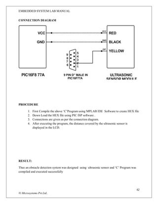
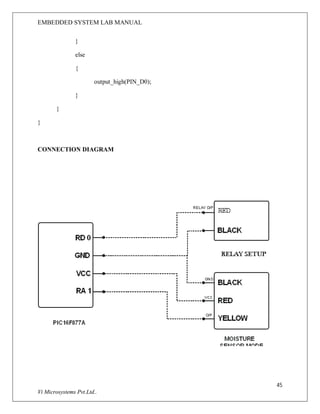
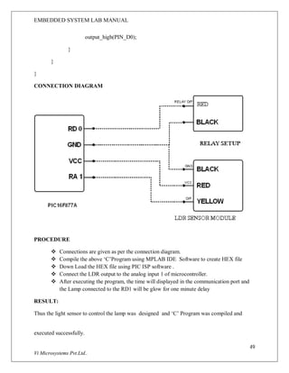
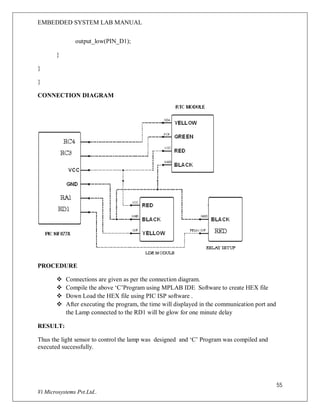
CONNECTION DIAGRAM
Vcc
RC4
RC3
GND
PIC16F877A RTC Module
Vcc
Sda
Scl
GND
PROCEDURE
1. Compile the above ‘C’Program using MPLAB IDE Software to create HEX file
2. Down Load the HEX file using PIC ISP software .](https://image.slidesharecdn.com/174085193-pic-prgm-manual-141204092550-conversion-gate02/85/174085193-pic-prgm-manual-17-320.jpg)
![EMBEDDED SYSTEM LAB MANUAL
20
Vi Microsystems Pvt.Ltd..
Another important characteristic of the LM35DZ is that it draws only 60 micro amps from its
supply and possesses a low self-heating capability. The sensor self-heating causes less than 0.1
oC temperature rise in still air.
connect the +Vs Pin to 5v and GND to GND. The output must be connected to the analog input
pin 2 of the PIC16f877A MCU. It is labeled AN2 in the datasheet. It is pin number 4 on the 40
pin package. It is also called RA2 because it is shared with PORTA2.
PROGRAM
#include<16f877.h>
#use delay(clock=20000000)
#use rs232(baud=9600,xmit=pin_c6,rcv=pin_c7)
#use I2C(master, sda=PIN_C4, scl=PIN_C3)
float value;
unsigned int i=0;
unsigned char arr[10]={0x3f,0x06,0x5b,0x4f,0x66,0x6d,0x7d,0x07,0x7f,0x67};
void delay(unsigned long int del)
{
while(del--);
}
void write_seg(int x1,int x2)
{
i2c_start();
i2c_write(0x40);
i2c_write(arr[x1]);
i2c_stop();
i2c_start();](https://image.slidesharecdn.com/174085193-pic-prgm-manual-141204092550-conversion-gate02/85/174085193-pic-prgm-manual-20-320.jpg)
![EMBEDDED SYSTEM LAB MANUAL
21
Vi Microsystems Pvt.Ltd..
i2c_write(0x42);
i2c_write(arr[x2]);
i2c_stop();
}
void main()
{
setup_adc_ports( ALL_ANALOG );
setup_adc(ADC_CLOCK_INTERNAL );
while(1)
{
set_adc_channel( 2 );
value = read_adc();
value = value;
i=((int)(value));
i=(i*2);
printf(" Temperature in Cel %d nr",i);
if(i>=99){i=99;}
write_seg(i/10,i%10);
delay(48000);
}
}](https://image.slidesharecdn.com/174085193-pic-prgm-manual-141204092550-conversion-gate02/85/174085193-pic-prgm-manual-21-320.jpg)
![EMBEDDED SYSTEM LAB MANUAL
25
Vi Microsystems Pvt.Ltd..
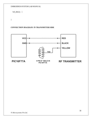
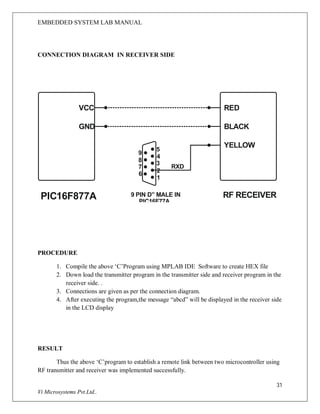
EX NO:6 REMOTE CONTROL THROUGH FM LINK
AIM:
ToWrite a ‘C’ Program to establish a remote link between two microcontroller using RF
transmitter and receiver and send the message “abcd” from the transmitter side to receiver side.
APPARATUS REQUIRED
1. PIC16F877A KIT
2. 5 V ADAPTER
3. RS232 CABLE.
SOFTWARE USED
1. MPLAB IDE COMPILER.
2. PIC ISP DOWNLOADER
PROGRAM IN TRANSMITTER SIDE
#include<16f877a.h>
#include<stdio.h>
#use delay(clock=20000000)
#use rs232(baud=1200,xmit=pin_C6,rcv=pin_C7)
unsigned char receive[5];
unsigned char a='a';
unsigned char b='b';
unsigned char c[4]="abc";
int i;
int j;
void rx()
{
unsigned int i;
for(i=0;i<5;i++)
{](https://image.slidesharecdn.com/174085193-pic-prgm-manual-141204092550-conversion-gate02/85/174085193-pic-prgm-manual-25-320.jpg)
![EMBEDDED SYSTEM LAB MANUAL
26
Vi Microsystems Pvt.Ltd..
receive[i]=getch();
}
}
void tx(unsigned char y[])
{
for(i=0;y[i]!='0';i++)
{
putchar(y[i]);
}
}
void wait(int z)
{
int i;
for(i=0;i<z;i++){}
}
void main()
{
while(1)
{
for(j=0;j<10000;j++)
{
printf("%c",a);](https://image.slidesharecdn.com/174085193-pic-prgm-manual-141204092550-conversion-gate02/85/174085193-pic-prgm-manual-26-320.jpg)


![EMBEDDED SYSTEM LAB MANUAL
37
Vi Microsystems Pvt.Ltd..
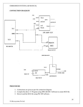
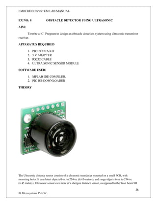
distance sensor. Use the IR distance sensor for targeted distance measurement, and the ultrasonic distance
sensor for wide-range applications. Car based applications include, backup sensors, parking sensors, curb
sensors, and more. Home automation applications include room monitoring, garage parking sensors, and
more.
This UltraSonic Distance Sensor is perfect for any number of applications that require you to perform
measurements between moving or stationary objects. Naturally, robotics applications are very popular but
you'll also find this product to be useful in security systems or as an infrared replacement if so
desired.This is extreamily suitable for Roboic Application, since it need only one I/O pin and very fast.
The "ECHO" does not require any ADC or USART to meassure the distance. Since it is very stable ,the
"ECHO" Ultrasonic sensor module can be used for Micromouse application instead of IR sensor.
PROGRAM
#include<16f877a.h>
#include<stdlib.h>
#include<string.h>
#include<stdio.h>
#use delay(clock=20000000)
#use rs232(baud=9600,xmit=pin_c6,rcv=pin_c7,stream=GPS)
int i=0;int a1;char a[];
void delay(unsigned long del)
{
while(del--);
}
void lcd_cmd(unsigned char cmd)
{](https://image.slidesharecdn.com/174085193-pic-prgm-manual-141204092550-conversion-gate02/85/174085193-pic-prgm-manual-37-320.jpg)
![EMBEDDED SYSTEM LAB MANUAL
39
Vi Microsystems Pvt.Ltd..
lcd_cmd(0X38);
delay(500);
lcd_cmd(0X06);
delay(500);
lcd_cmd(0X0C);
delay(500);
lcd_cmd(0X01);
delay(500);
lcd_cmd(0X80);
delay(500);
}
void lcd_disp(unsigned char w[],unsigned char add)
{
unsigned char i=0;
for(i=0;w[i]!='0';i++)
{
lcd_cmd(add+i);
lcd_dat(w[i]);
delay(500);
}
}
void lcd_con(unsigned int con)
{](https://image.slidesharecdn.com/174085193-pic-prgm-manual-141204092550-conversion-gate02/85/174085193-pic-prgm-manual-39-320.jpg)
![EMBEDDED SYSTEM LAB MANUAL
40
Vi Microsystems Pvt.Ltd..
lcd_dat(((con%1000)/100)+0x30);
lcd_dat(((con%100)/10)+0x30);
lcd_dat((con%10)+0x30);
}
void print()
{
unsigned char arr[]={"DISTANCE IN CMS"};
lcd_disp(arr,0x80);
}
void get()
{
do{;}while(getc()!='R');
a1=( (getc()-48)*100)+( (getc()-48)*10)+ (getc()-48);
}
void main()](https://image.slidesharecdn.com/174085193-pic-prgm-manual-141204092550-conversion-gate02/85/174085193-pic-prgm-manual-40-320.jpg)


![Pic microcontroller [autosaved] [autosaved]](https://cdn.slidesharecdn.com/ss_thumbnails/picmicrocontrollerautosavedautosaved-120427093459-phpapp02-thumbnail.jpg?width=640&height=640&fit=bounds)