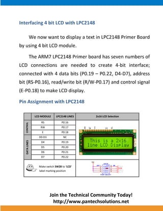
ARM HOW-TO GUIDE Interfacing LCD with LPC2148 ARM
Join the Technical Community Today! 
http://www.pantechsolutions.net 
Contents at a Glance 
ARM7 LPC2148 Primer Board ........................................... 3 
LCD (Liquid Crystal Display) .............................................. 3 
Interfacing LCD ................................................................ 4 
Interfacing 4 bit LCD with LPC2148 ................................... 5 
Pin Assignment with LPC2148 .......................................... 5 
Circuit Diagram to Interface 4 bit LCD with LPC2148 ......... 6 
Source Code .................................................................... 6 
C Program to display a text in 4 bit LCD using LPC2148 ..... 7 
Testing the LCD Module with LPC2148 ........................... 10 
General Information ...................................................... 11
Join the Technical Community Today! 
http://www.pantechsolutions.net 
ARM7 LPC2148 Primer Board 
The ARM7 LPC2148 Primer board is specifically designed to help students to master the required skills in the area of embedded systems. The kit is designed in such way that all the possible features of the microcontroller will be easily used by the students. The kit supports in system programming (ISP) which is done through serial port. NXP’s ARM7 (LPC2148), ARM Primer Kit is proposed to smooth the progress of developing and debugging of various designs encompassing of High speed 32-bit Microcontrollers. 
LCD (Liquid Crystal Display) 
Liquid Crystal Display also called as LCD is very helpful in providing user interface as well as for debugging purpose. A liquid crystal display (LCD) is a flat panel display that uses the light modulating properties of liquid crystals (LCs). LCD Modules can present textual information to user.
Join the Technical Community Today! 
http://www.pantechsolutions.net 
Interfacing LCD 
Fig. 1 shows how to interface the LCD to microcontroller. The 2x16 character LCD interface card with supports both modes 4-bit and 8-bit interface, and also facility to adjust contrast through trim pot. In 4-bit interface 7 lines needed to create 4-bit interface; 4 data bits (D0 – D3), three control lines, address bit (RS), read/write bit (R/W) and control signal (E). 
Fig. 1 Interfacing 4 bit LCD to Microcontroller
Join the Technical Community Today! 
http://www.pantechsolutions.net 
Interfacing 4 bit LCD with LPC2148 
We now want to display a text in LPC2148 Primer Board 
by using 4 bit LCD module. 
The ARM7 LPC2148 Primer board has seven numbers of 
LCD connections are needed to create 4-bit interface; 
connected with 4 data bits (P0.19 – P0.22, D4-D7), address 
bit (RS-P0.16), read/write bit (R/W-P0.17) and control signal 
(E-P0.18) to make LCD display. 
Pin Assignment with LPC2148 
LCD MODULE LPC2148 LINES 2x16 LCD Selection 
CONTROL 
RS P0.16 
RW P0.17 
E P0.18 
DATA LINES 
D0-D3 NC 
D4 P0.19 
D5 P0.20 
D6 P0.21 
D7 P0.22 
Make switch SW28 to ‘LCD’ 
label marking position 
+5V 
OFF ON 
SW28 
PWR ON/OFF 
1 
2 
3 
4 
8 
7 
6 
5 
LCD 
7SEG 
GLCD 
SM/RL 
GND 
VCC 
VEE 
RS 
R/W 
E 
D4 
D5 
D6 
D7 
LED+ 
LED-
Join the Technical Community Today! 
http://www.pantechsolutions.net 
Circuit Diagram to Interface 4 bit LCD with LPC2148 
Source Code 
The Interfacing 4 bit LCD with LPC2148 program is very simple and straight forward, which display a text in 2 X 16 LCD module using 4 data lines only. Some delay is occurring when a single command / data is executed. 
RSC5222pf3.3VC5322pfX2112MHzLPC2148U16VSS16 VDDA7 VSS218 VDD323 VSS325 VDD243 VSS442 VREF63XTAL162XTAL261 VSSA59 VDD151 VSS550P0.222P0.211P0.2055P0.1954P0.1853P0.1747P0.1646RWJP122X16 LCD11223344556677889910101111121213131414151516161717181819192020D7+5VENR3010K13 2 D4D6D5
Join the Technical Community Today! 
http://www.pantechsolutions.net 
C Program to display a text in 4 bit LCD using LPC2148 
*************************************************************************************** Title : Program to 4 bit LCD display *************************************************************************************** #include <lpc214x.h> #include <stdio.h> #define RS 0x10000 #define RW 0x20000 #define EN 0x40000 void lcd_cmd (unsigned char); void lcd_data (unsigned char); void lcd_initialize (void); void lcd_display (void); void LCD4_Convert(unsigned char); const unsigned char cmd[4] = {0x28,0x0c,0x06,0x01}; unsigned char msg[] = {">PS-Primer 2148<"}; unsigned char msg1[]= {":: LCD Demo! ::"}; void main() { PINSEL1 = 0; IODIR0 = 0xFF << 16; lcd_initialize(); lcd_display(); while(1); } void delay(unsigned int n) { unsigned int i,j; for(i=0;i<n;i++) for(j=0;j<12000;j++); }
Join the Technical Community Today! 
http://www.pantechsolutions.net 
void lcd_cmd(unsigned char data) { IOCLR0 |= RS; //0x1000; //RS IOCLR0 |= RW; //0x2000; //RW LCD4_Convert(data); } void lcd_initialize(void) { int i; for(i=0;i<4;i++) { IOCLR0 = 0xF << 19; //IOCLR 0/1 lcd_cmd(cmd[i]); delay(15); } } void lcd_data (unsigned char data) { IOSET0 |= RS; //0x1000; //RS IOCLR0 |= RW; //0x2000; //RW LCD4_Convert(data); } void lcd_display (void) { char i; /* first line message */ lcd_cmd(0x80); delay(15); i=0; while(msg[i]!='0') { delay(5); lcd_data(msg[i]); i++; }
Join the Technical Community Today! 
http://www.pantechsolutions.net 
delay(15); /* second line message */ lcd_cmd(0xc0); delay(15); i=0; while(msg1[i]!='0') { delay(5); lcd_data(msg1[i]); i++; } delay(15); } void LCD4_Convert(unsigned char c) { if(c & 0x80) IOSET0 = 1 << 22; else IOCLR0 = 1 << 22; if(c & 0x40) IOSET0 = 1 << 21; else IOCLR0 = 1 << 21; if(c & 0x20) IOSET0 = 1 << 20; else IOCLR0 = 1 << 20; if(c & 0x10) IOSET0 = 1 << 19; else IOCLR0 = 1 << 19; IOSET0 = EN; delay(8); IOCLR0 = EN; if(c & 0x08) IOSET0 = 1 << 22; else IOCLR0 = 1 << 22; if(c & 0x04) IOSET0 = 1 << 21; else IOCLR0 = 1 << 21; if(c & 0x02) IOSET0 = 1 << 20; else IOCLR0 = 1 << 20; if(c & 0x01) IOSET0 = 1 << 19; else IOCLR0 = 1 << 19; IOSET0 = EN; delay(8); IOCLR0 = EN; }
Join the Technical Community Today! 
http://www.pantechsolutions.net 
To compile the above C code you need the KEIL software. They must be properly set up and a project with correct settings must be created in order to compile the code. To compile the above code, the C file must be added to the project. In Keil, you want to develop or debug the project without any hardware setup. You must compile the code for generating HEX file. In debugging Mode, you want to check the port output without microcontroller Board. The Flash Magic software is used to download the hex file into your microcontroller through UART0. 
Testing the LCD Module with LPC2148 
Give +3.3V power supply to LPC2148 Primer Board; the LCD is connected with microcontroller LPC2148 Primer Board. When the program is downloading into LPC2148 in Primer Board, the screen should show the text messages.
Join the Technical Community Today! 
http://www.pantechsolutions.net 
If you not reading any text from LCD, then you just check the jumper connections & adjust the trim pot level. Otherwise you just check it with debugging mode in Keil. If you want to see more details about debugging just see the videos in below link. 
 How to Create & Debug a Project in Keil. 
General Information 
For proper working use the components of exact values as shown in Circuit file. Wherever possible use new components. Solder everything in a clean way. A major problem arises due to improper soldering, solder jumps and loose joints. Use the exact value crystal shown in schematic. More instructions are available in following articles, 
 User Manual of LPC2148 Primer Board. 
 Tutorial of how to create & Debug a project in Keil.
Join the Technical Community Today! 
http://www.pantechsolutions.net 
Pantech solutions creates information packed technical documents like this one every month. And our website is a rich and trusted resource used by a vibrant online community of more than 1,00,000 members from organization of all shapes and sizes. 
Did you enjoy the read?
Join the Technical Community Today! 
http://www.pantechsolutions.net 
What do we sell? Our products range from Various Microcontroller development boards, DSP Boards, FPGA/CPLD boards, Communication Kits, Power electronics, Basic electronics, Robotics, Sensors, Electronic components and much more . Our goal is to make finding the parts and information you need easier and affordable so you can create awesome projects and training from Basic to Cutting edge technology.

4 bit lcd_interfacing_with_arm7_primer

  • 1.
    ARM HOW-TO GUIDEInterfacing LCD with LPC2148 ARM
  • 2.
    Join the TechnicalCommunity Today! http://www.pantechsolutions.net Contents at a Glance ARM7 LPC2148 Primer Board ........................................... 3 LCD (Liquid Crystal Display) .............................................. 3 Interfacing LCD ................................................................ 4 Interfacing 4 bit LCD with LPC2148 ................................... 5 Pin Assignment with LPC2148 .......................................... 5 Circuit Diagram to Interface 4 bit LCD with LPC2148 ......... 6 Source Code .................................................................... 6 C Program to display a text in 4 bit LCD using LPC2148 ..... 7 Testing the LCD Module with LPC2148 ........................... 10 General Information ...................................................... 11
  • 3.
    Join the TechnicalCommunity Today! http://www.pantechsolutions.net ARM7 LPC2148 Primer Board The ARM7 LPC2148 Primer board is specifically designed to help students to master the required skills in the area of embedded systems. The kit is designed in such way that all the possible features of the microcontroller will be easily used by the students. The kit supports in system programming (ISP) which is done through serial port. NXP’s ARM7 (LPC2148), ARM Primer Kit is proposed to smooth the progress of developing and debugging of various designs encompassing of High speed 32-bit Microcontrollers. LCD (Liquid Crystal Display) Liquid Crystal Display also called as LCD is very helpful in providing user interface as well as for debugging purpose. A liquid crystal display (LCD) is a flat panel display that uses the light modulating properties of liquid crystals (LCs). LCD Modules can present textual information to user.
  • 4.
    Join the TechnicalCommunity Today! http://www.pantechsolutions.net Interfacing LCD Fig. 1 shows how to interface the LCD to microcontroller. The 2x16 character LCD interface card with supports both modes 4-bit and 8-bit interface, and also facility to adjust contrast through trim pot. In 4-bit interface 7 lines needed to create 4-bit interface; 4 data bits (D0 – D3), three control lines, address bit (RS), read/write bit (R/W) and control signal (E). Fig. 1 Interfacing 4 bit LCD to Microcontroller
  • 5.
    Join the TechnicalCommunity Today! http://www.pantechsolutions.net Interfacing 4 bit LCD with LPC2148 We now want to display a text in LPC2148 Primer Board by using 4 bit LCD module. The ARM7 LPC2148 Primer board has seven numbers of LCD connections are needed to create 4-bit interface; connected with 4 data bits (P0.19 – P0.22, D4-D7), address bit (RS-P0.16), read/write bit (R/W-P0.17) and control signal (E-P0.18) to make LCD display. Pin Assignment with LPC2148 LCD MODULE LPC2148 LINES 2x16 LCD Selection CONTROL RS P0.16 RW P0.17 E P0.18 DATA LINES D0-D3 NC D4 P0.19 D5 P0.20 D6 P0.21 D7 P0.22 Make switch SW28 to ‘LCD’ label marking position +5V OFF ON SW28 PWR ON/OFF 1 2 3 4 8 7 6 5 LCD 7SEG GLCD SM/RL GND VCC VEE RS R/W E D4 D5 D6 D7 LED+ LED-
  • 6.
    Join the TechnicalCommunity Today! http://www.pantechsolutions.net Circuit Diagram to Interface 4 bit LCD with LPC2148 Source Code The Interfacing 4 bit LCD with LPC2148 program is very simple and straight forward, which display a text in 2 X 16 LCD module using 4 data lines only. Some delay is occurring when a single command / data is executed. RSC5222pf3.3VC5322pfX2112MHzLPC2148U16VSS16 VDDA7 VSS218 VDD323 VSS325 VDD243 VSS442 VREF63XTAL162XTAL261 VSSA59 VDD151 VSS550P0.222P0.211P0.2055P0.1954P0.1853P0.1747P0.1646RWJP122X16 LCD11223344556677889910101111121213131414151516161717181819192020D7+5VENR3010K13 2 D4D6D5
  • 7.
    Join the TechnicalCommunity Today! http://www.pantechsolutions.net C Program to display a text in 4 bit LCD using LPC2148 *************************************************************************************** Title : Program to 4 bit LCD display *************************************************************************************** #include <lpc214x.h> #include <stdio.h> #define RS 0x10000 #define RW 0x20000 #define EN 0x40000 void lcd_cmd (unsigned char); void lcd_data (unsigned char); void lcd_initialize (void); void lcd_display (void); void LCD4_Convert(unsigned char); const unsigned char cmd[4] = {0x28,0x0c,0x06,0x01}; unsigned char msg[] = {">PS-Primer 2148<"}; unsigned char msg1[]= {":: LCD Demo! ::"}; void main() { PINSEL1 = 0; IODIR0 = 0xFF << 16; lcd_initialize(); lcd_display(); while(1); } void delay(unsigned int n) { unsigned int i,j; for(i=0;i<n;i++) for(j=0;j<12000;j++); }
  • 8.
    Join the TechnicalCommunity Today! http://www.pantechsolutions.net void lcd_cmd(unsigned char data) { IOCLR0 |= RS; //0x1000; //RS IOCLR0 |= RW; //0x2000; //RW LCD4_Convert(data); } void lcd_initialize(void) { int i; for(i=0;i<4;i++) { IOCLR0 = 0xF << 19; //IOCLR 0/1 lcd_cmd(cmd[i]); delay(15); } } void lcd_data (unsigned char data) { IOSET0 |= RS; //0x1000; //RS IOCLR0 |= RW; //0x2000; //RW LCD4_Convert(data); } void lcd_display (void) { char i; /* first line message */ lcd_cmd(0x80); delay(15); i=0; while(msg[i]!='0') { delay(5); lcd_data(msg[i]); i++; }
  • 9.
    Join the TechnicalCommunity Today! http://www.pantechsolutions.net delay(15); /* second line message */ lcd_cmd(0xc0); delay(15); i=0; while(msg1[i]!='0') { delay(5); lcd_data(msg1[i]); i++; } delay(15); } void LCD4_Convert(unsigned char c) { if(c & 0x80) IOSET0 = 1 << 22; else IOCLR0 = 1 << 22; if(c & 0x40) IOSET0 = 1 << 21; else IOCLR0 = 1 << 21; if(c & 0x20) IOSET0 = 1 << 20; else IOCLR0 = 1 << 20; if(c & 0x10) IOSET0 = 1 << 19; else IOCLR0 = 1 << 19; IOSET0 = EN; delay(8); IOCLR0 = EN; if(c & 0x08) IOSET0 = 1 << 22; else IOCLR0 = 1 << 22; if(c & 0x04) IOSET0 = 1 << 21; else IOCLR0 = 1 << 21; if(c & 0x02) IOSET0 = 1 << 20; else IOCLR0 = 1 << 20; if(c & 0x01) IOSET0 = 1 << 19; else IOCLR0 = 1 << 19; IOSET0 = EN; delay(8); IOCLR0 = EN; }
  • 10.
    Join the TechnicalCommunity Today! http://www.pantechsolutions.net To compile the above C code you need the KEIL software. They must be properly set up and a project with correct settings must be created in order to compile the code. To compile the above code, the C file must be added to the project. In Keil, you want to develop or debug the project without any hardware setup. You must compile the code for generating HEX file. In debugging Mode, you want to check the port output without microcontroller Board. The Flash Magic software is used to download the hex file into your microcontroller through UART0. Testing the LCD Module with LPC2148 Give +3.3V power supply to LPC2148 Primer Board; the LCD is connected with microcontroller LPC2148 Primer Board. When the program is downloading into LPC2148 in Primer Board, the screen should show the text messages.
  • 11.
    Join the TechnicalCommunity Today! http://www.pantechsolutions.net If you not reading any text from LCD, then you just check the jumper connections & adjust the trim pot level. Otherwise you just check it with debugging mode in Keil. If you want to see more details about debugging just see the videos in below link.  How to Create & Debug a Project in Keil. General Information For proper working use the components of exact values as shown in Circuit file. Wherever possible use new components. Solder everything in a clean way. A major problem arises due to improper soldering, solder jumps and loose joints. Use the exact value crystal shown in schematic. More instructions are available in following articles,  User Manual of LPC2148 Primer Board.  Tutorial of how to create & Debug a project in Keil.
  • 12.
    Join the TechnicalCommunity Today! http://www.pantechsolutions.net Pantech solutions creates information packed technical documents like this one every month. And our website is a rich and trusted resource used by a vibrant online community of more than 1,00,000 members from organization of all shapes and sizes. Did you enjoy the read?
  • 13.
    Join the TechnicalCommunity Today! http://www.pantechsolutions.net What do we sell? Our products range from Various Microcontroller development boards, DSP Boards, FPGA/CPLD boards, Communication Kits, Power electronics, Basic electronics, Robotics, Sensors, Electronic components and much more . Our goal is to make finding the parts and information you need easier and affordable so you can create awesome projects and training from Basic to Cutting edge technology.