Download as PDF, PPTX


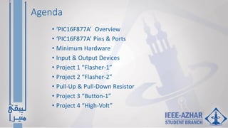
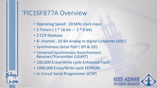
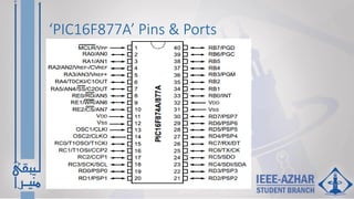
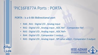
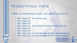
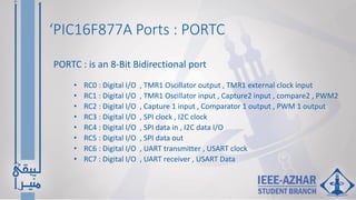
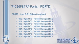
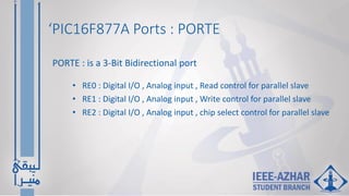
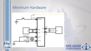
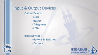
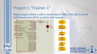
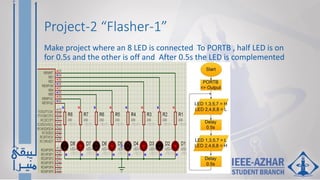
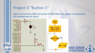
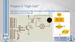


This document provides an overview and agenda for interfacing with the PIC16F877A microcontroller. It discusses the microcontroller's pins and ports, including PORTA-PORTE. It describes the minimum hardware needed and some example input and output devices like LEDs, buttons, and sensors. It then outlines 4 projects involving flashing LEDs, toggling an LED with a button press, and turning on a 220V lamp with a button. The document provides information on timers, analog to digital conversion, communication protocols, and other features of the PIC16F877A.


![Pic microcontroller [autosaved] [autosaved]](https://cdn.slidesharecdn.com/ss_thumbnails/picmicrocontrollerautosavedautosaved-120427093459-phpapp02-thumbnail.jpg?width=640&height=640&fit=bounds)