Downloaded 4,965 times
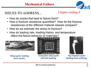
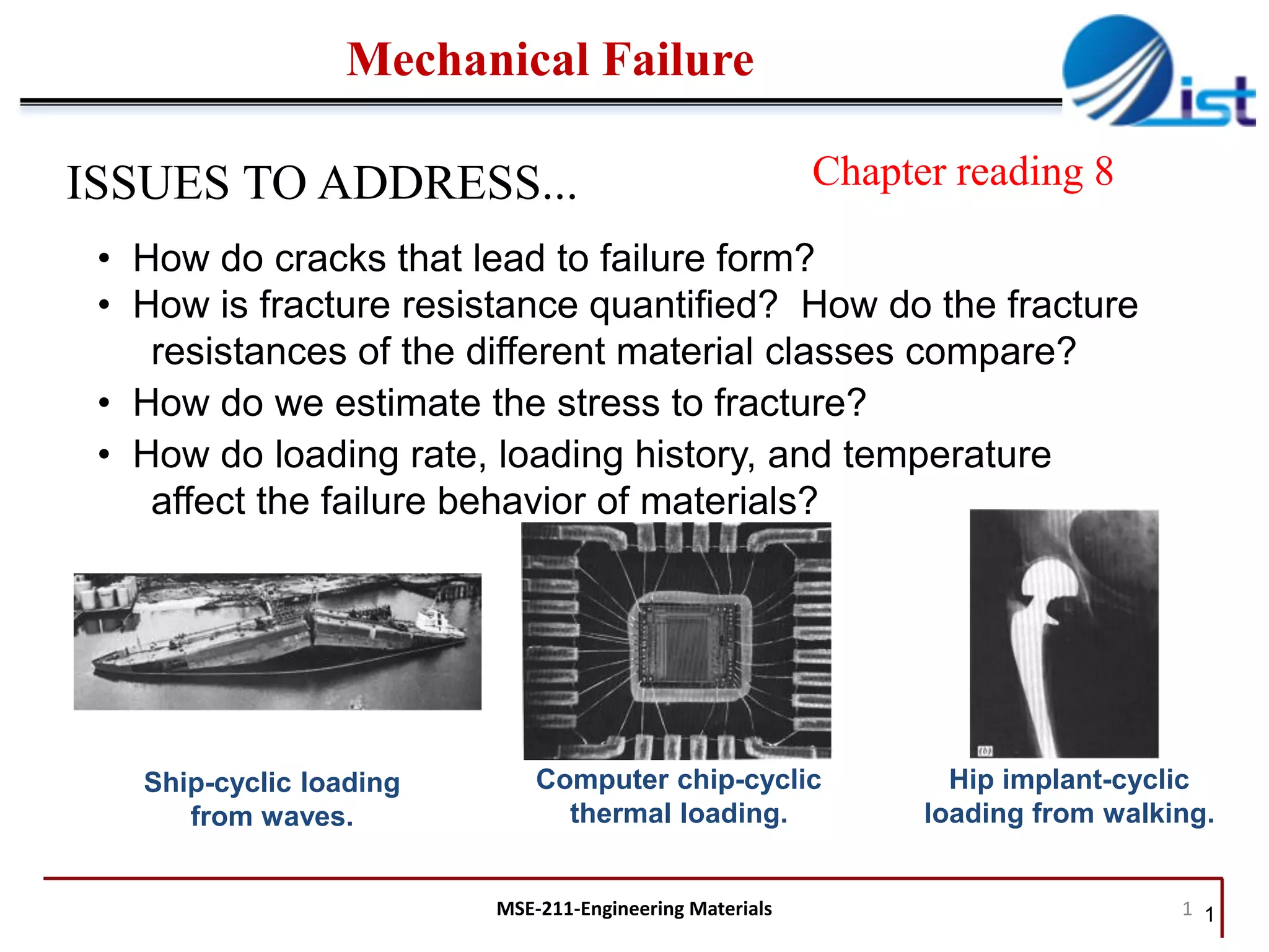
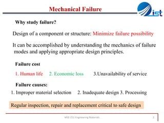
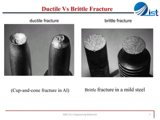
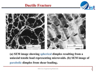
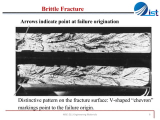
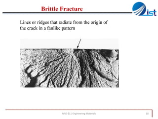
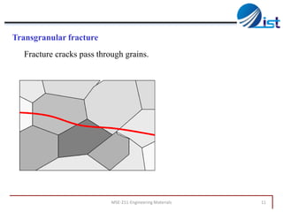
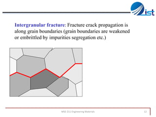
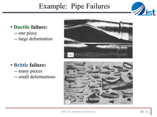
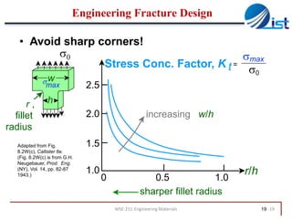
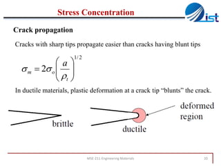
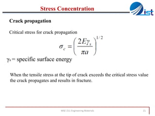
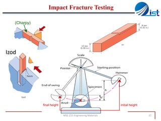
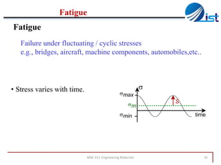
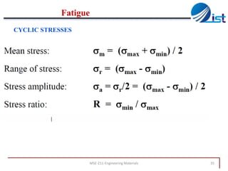
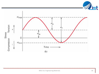
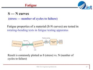
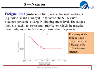
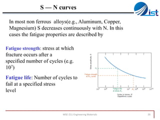
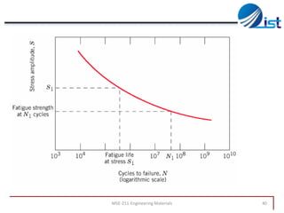


The document discusses mechanical failure and fracture in materials. It addresses how cracks form and propagate, leading to brittle or ductile fracture depending on the material. Stress concentration at crack tips is a key factor. Fracture toughness and impact testing methods are introduced to characterize a material's resistance to fracture. Fatigue failure from cyclic stresses often initiates at flaws and can occur at stresses below typical strength values. S-N curves relate the cyclic stress amplitude to the lifetime of a material. Temperature and loading conditions also influence failure behavior.


![ME 312 Mechanical Machine Design [Screws, Bolts, Nuts]](https://cdn.slidesharecdn.com/ss_thumbnails/me312-dsulec10-screws-170213050612-thumbnail.jpg?width=640&height=640&fit=bounds)