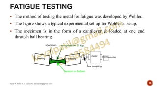
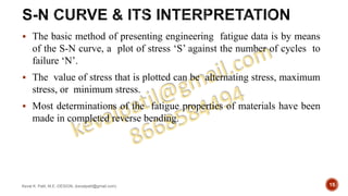
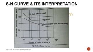
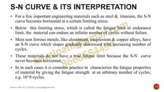
SlideShare a Scribd company logo
1 of 27
i. Fracture
ii. Fatigue failure
iii. creep
Keval K. Patil, M.E.-DESIGN, (kevalpatil@gmail.com)
1
Keval K. Patil, M.E.-DESIGN, (kevalpatil@gmail.com)
Part 2
2
 Fatigue is a form of failure that occurs in structures subjected to
dynamic & fluctuating stresses (e.g., bridges, aircraft, & machine
components).
 Under these circumstances it is possible for failure to occur at a stress
level considerably lower than the tensile or yield strength for a static
load.
 The term “fatigue” is used because this type of failure normally
occurs after a lengthy period of repeated stress or strain cycling.
 Fatigue is important inasmuch as it is the single largest cause of
failure in metals, estimated to comprise approximately 90% of all
metallic failures; polymers & ceramics (except for glasses) are also
susceptible to this type of failure.
Keval K. Patil, M.E.-DESIGN, (kevalpatil@gmail.com) 3
 Furthermore, fatigue is catastrophic & insidious, occurring very
suddenly & without warning.
 Fatigue failure is brittle like in nature even in normally ductile metals,
in that there is very little, if any, gross plastic deformation associated
with failure.
 The process occurs by the initiation & propagation of cracks, &
ordinarily the fracture surface is perpendicular to the direction of an
applied tensile stress.
Keval K. Patil, M.E.-DESIGN, (kevalpatil@gmail.com) 4
• Cyclic stress distribution of forces (a stress)
that changes over time in a repetitive fashion.
• When cyclic stresses are applied to a material,
even though the stresses do not cause plastic
deformation, the material may fail due to
fatigue.
• Fatigue failure is typically modeled by
decomposing cyclic stresses into mean &
alternating components.
• Mean stress is the time average of the principal
stress.
• The definition of alternating stress varies
between different sources.
• It is either defined as the difference between
the minimum & the maximum stress, or the
difference between the mean & maximum
stress.
Keval K. Patil, M.E.-DESIGN, (kevalpatil@gmail.com) 5
 It can be developed in four stages.
 Crack nucleation;
 Crack-growth;
 Ultimate failure.
 Crack Nucleation:
 Fatigue failure begins with formation of a small crack, generally at some
point on the external surface
Keval K. Patil, M.E.-DESIGN, (kevalpatil@gmail.com) 6
 Crack Growth:
 The crack formed on surface is then develops slowly into the material in a direction
roughly perpendicular to the main tensile axis.
 Ultimately the cross- sectional area of the member will have been so reduced that it
can no longer withstand the applied load & ordinary tensile fracture will result path
which the crack has followed
 Fracture:
 A fatigue crack ‘front’ advances a small amount during each stress cycle & each
increment of advance is shown on the fracture surface as a minute ripple line.
 These ripple lines radiate out from the origin of fracture as a series of
approximately concentric arcs.
 These individual ripples are visible only by very high-powered metallographic
methods. Few ripples much larger than the rest & shows the general
Keval K. Patil, M.E.-DESIGN, (kevalpatil@gmail.com) 7
 The figure shows mechanism of fatigue failure in three stages.
 The crack propagates slowly from the source, the fracture surface rub together
due to pulsating nature of the stress & so the surface become burnished.
 Fatigue failure in metals is very easy to identify.
 The fatigue cracks are not result of brittle fracture but of plastic slip.
Keval K. Patil, M.E.-DESIGN, (kevalpatil@gmail.com) 8
 A number of theories (or mechanism) proposed for
fatigue failure are as follow
 Orowan’s theory
 Wood’s theory
 Cottrell & hull theory
 Mott theory
Keval K. Patil, M.E.-DESIGN, (kevalpatil@gmail.com) 9
 Orowan’s theory
 The metal is considered to contain small, weak regions, which may be areas
of favourable orientation for slip or areas of high stress concentration due to
metallurgical notches such as inclusions.
 If the loading or the stress is such that the total plastic strain in the weak
region exceeds the critical value, a crack is formed.
 Mott theory
 Mott suggested a model involving the cross slip of screw dislocations & as a
result a column of metal is extruded from the surface & a cavity is left behind
in the interior of the crystal which is source of fatigue crack & ultimately the
fatigue fracture occurs
Keval K. Patil, M.E.-DESIGN, (kevalpatil@gmail.com) 10
 Wood interprets microscopic observation of slip produced by fatigue as
indicated that slip bands are the result of a systematic build-up of fine slip
movement, corresponding movements of the order of 10^-5 to 10^-4 cm,
which are observed for static slip bands.
 According to wood, the back & fort fine slip movement of fatigue could
build up notches or ridges at the surface as shown in figure.
 These notches act as stress raisers & this way starts a fatigue crack which
ultimately leads to fatigue fracture.
Keval K. Patil, M.E.-DESIGN, (kevalpatil@gmail.com) 11
 A model involving the interaction of edge dislocation on slip systems was
suggested by Cottrell & Hull.
 Two different slip systems when work with different directions & planes of
slip produce slip step at surface, thereby forming intrusions & extrusions as
shown in figure
 Fatigue crack starts from intrusions at the surface.
Keval K. Patil, M.E.-DESIGN, (kevalpatil@gmail.com) 12
 The method of testing the metal for fatigue was developed by Wohler.
 The figure shows a typical experimental set up for Wohler’s setup.
 The specimen is in the form of a cantilever & loaded at one end
through ball bearing.
Keval K. Patil, M.E.-DESIGN, (kevalpatil@gmail.com) 13
tension on bottom
compression on top
counter
motor
flex coupling
specimen
bearing bearing
 It is rotated by means of a high speed motor to which a counter is
attached to count the number of rotations.
 At any instant, the upper surface of the specimen is under tension &
lower surface is under compression, with the neutral axis.
 In one rotation, the specimen undergoes two cyclic fluctuations of
stress.
 The number of cycles to cause failure will vary with the applied stress.
 Higher the stress, lower will be the cycles to cause failure.
 Similarly, if the stress is lowered, more number of cycles required to
cause failure.
Keval K. Patil, M.E.-DESIGN, (kevalpatil@gmail.com) 14
 The basic method of presenting engineering fatigue data is by means
of the S-N curve, a plot of stress ‘S’ against the number of cycles to
failure ‘N’.
 The value of stress that is plotted can be alternating stress, maximum
stress, or minimum stress.
 Most determinations of the fatigue properties of materials have been
made in completed reverse bending.
Keval K. Patil, M.E.-DESIGN, (kevalpatil@gmail.com) 15
Keval K. Patil, M.E.-DESIGN, (kevalpatil@gmail.com) 16
 For a few important engineering materials such as steel & titanium, the S-N
curve becomes horizontal at a certain limiting stress.
 Below this limiting stress, which is called the fatigue limit or endurance
limit, the material can endure an infinite number of cycles without failure.
 Most non ferrous metals, like aluminium, magnesium & copper alloys, have
an S-N curve which slopes gradually downward with increasing number of
cycles.
 These materials do not have a true fatigue limit because the S-N curve
never becomes horizontal.
 In in such cases it is common practice to characterize the fatigue properties
of material by giving the fatigue strength at an arbitrary number of cycles,
e.g. 10^8 cycles.
Keval K. Patil, M.E.-DESIGN, (kevalpatil@gmail.com) 17
 Fatigue strength is seriously reduced by following factors:
 Notch effect
 Surface effect
 Corrosion fatigue
 Thermal fatigue
 Pre-stressing
Keval K. Patil, M.E.-DESIGN, (kevalpatil@gmail.com) 18
 Fatigue strength of material is reduced by presence of notch in the
material.
 E.g. Machine element it contains fillets, keyways, screw threads and
holes.
 Fatigue cracks in structure parts usually starts at such geometrical
irregularities.
 The effect of fatigue is generally studied by specimens containing a
‘V’ notch or a circular notch.
 The effect of notches on fatigue strength is determined by comparing
the S-N curves of notched and un-notched specimens.
Keval K. Patil, M.E.-DESIGN, (kevalpatil@gmail.com) 19
 Fatigue failure can be produced by fluctuating thermal stress under conditions
where no stress are produced by mechanical causes.
 Thermal stress result when the change in dimensions of a member as the result of
a temperature change.
 For the simple case of a bar with fixed end supports, the thermal stress developed
by a temperature change ‘dT’ is
 σ = α*E*dT
 where ,
 α = Linear thermal coefficient of expansion.
 E = Elastic modulus
 If failure occurs by one application of thermal stress, the condition is called
thermal shock.
 However, if failure occurs after repeated application of thermal stress it is called
as Thermal fatigue.
Keval K. Patil, M.E.-DESIGN, (kevalpatil@gmail.com) 20
 All fatigue failures start at the surface. The factors which affect on the
surface of a fatigue specimen are roughly divided into 3 categories:
 Surface roughness
 Changes in surface properties
 Surface residual stress
 Surface roughness:
 Smoothly polished specimen in which the fine scratches are oriented parallel
with the direction of the principle tensile stress, give the highest values in
fatigue tests.
 Such polished specimen are usually used in laboratory fatigue tests and are
known as ‘par bars’.
Keval K. Patil, M.E.-DESIGN, (kevalpatil@gmail.com) 21
 Change in surface properties:
 Fatigue failure is dependent on the surface conditions.
 Decarburization of the surface of heat-treated steel reduces fatigue
performance.
 Carburizing and nitriding makes steel surface stronger and harder, which
improves fatigue properties.
 The fatigue performance is improved when notched fatigue specimens are
nitrided.
 Electroplating of surface generally decreases the fatigue limit of steel.
 Surface residual stress:
 Residual stresses are stresses that exist in a part independent of any external
force.
 Nearly every manufacturing operation will result in residual stresses in varying
degrees.
 Residual stresses are beneficial when they are opposite to the applied load.
Keval K. Patil, M.E.-DESIGN, (kevalpatil@gmail.com) 22
 The simultaneous action of cyclic stress and chemical attack is known
as corrosion fatigue.
 Corrosion attack without superimposed stress often produces pitting
of metal surfaces.
 The pits acts as notches and produce a reduction in fatigue strength.
 When corrosion and fatigue occur simultaneously, the chemical attack
greatly accelerates the rate at which fatigue cracks propagate.
 Material which shows a definite fatigue limit when tested in air at
room temperature shows no indication of a fatigue limit when the test
is carried out in a corrosive environment.
Keval K. Patil, M.E.-DESIGN, (kevalpatil@gmail.com) 23
 When fatigue test is carried out in air not affected by the speed of testing, over a
range from about 10 to 200 Hz, when test is carried out in corrosive environment
there is a definite dependence on testing speed.
 Since corrosive attack is a time-dependent phenomenon, the higher the testing speed,
the smaller the damage due to corrosion.
 In usual method, corrosion-fatigue test is carried out by continuously subjecting
specimen in combined influences of corrosion and cyclic stress until failure occurs.
 A number of method are available for minimizing corrosion-fatigue damage.
 In general material is protected from corrosive environment by metallic and non-
metallic coating is successful method.
 Nitriding is effective in minimizing corrosion fatigue.
Keval K. Patil, M.E.-DESIGN, (kevalpatil@gmail.com) 24
 Pre-stressing is the process of loading an engineering component
under controlled conditions to a cyclic stress for a fixed number of
cycles prior to any possibility of fatigue failure.
 When magnitude of pre-stressing is lower than the operating stress
level then it is known as under-stressing.
 Under controlled conditions when the magnitude of the stress is higher
than operating stress level the condition is called overstressing.
 The number of pre-stressing cycles is always lesser than the number
of cycles needed to cause fatigue failure.
 Pre-stressing is desirable under conditions of under-stressing.
Keval K. Patil, M.E.-DESIGN, (kevalpatil@gmail.com) 25
 An under stressed components always exhibits best fatigue resistance.
 For an over-stressed component the failure resistance is lesser
compared to a components that has been pre-stresses.
 Thus under stressing cause significant improvement in fatigue
behaviour by strengthening the weak regions and enhancing their
dynamic response to operating stress.
Keval K. Patil, M.E.-DESIGN, (kevalpatil@gmail.com) 26
Keval K. Patil, M.E.-DESIGN, (kevalpatil@gmail.com) 27

More Related Content

What's hot (20)

Mechanical Testing of Materials
Mechanical Testing of Materials Mechanical Testing of Materials
Mechanical Testing of Materials
 
Fatigue and creep
Fatigue and creepFatigue and creep
Fatigue and creep
 
Failure Mechanism In Ductile & Brittle Material
Failure Mechanism In Ductile & Brittle MaterialFailure Mechanism In Ductile & Brittle Material
Failure Mechanism In Ductile & Brittle Material
 
Ductile to brittle transition
Ductile to brittle transitionDuctile to brittle transition
Ductile to brittle transition
 
Creep Failure
Creep FailureCreep Failure
Creep Failure
 
Fatigue test
Fatigue testFatigue test
Fatigue test
 
Fatigue & Fracture
Fatigue & Fracture Fatigue & Fracture
Fatigue & Fracture
 
Fracture
FractureFracture
Fracture
 
Fatigue Mechanics of Materials
Fatigue Mechanics of MaterialsFatigue Mechanics of Materials
Fatigue Mechanics of Materials
 
12 fatigue of metals
12 fatigue of metals12 fatigue of metals
12 fatigue of metals
 
Theories of Failure
Theories of FailureTheories of Failure
Theories of Failure
 
Fracture mechanics
Fracture mechanicsFracture mechanics
Fracture mechanics
 
Metal fatigue ppt
Metal fatigue pptMetal fatigue ppt
Metal fatigue ppt
 
Fracture Mechanics & Failure Analysis: creep and stress rupture
Fracture Mechanics & Failure Analysis: creep and stress ruptureFracture Mechanics & Failure Analysis: creep and stress rupture
Fracture Mechanics & Failure Analysis: creep and stress rupture
 
Mech props
Mech propsMech props
Mech props
 
Fatigue testing
Fatigue testing Fatigue testing
Fatigue testing
 
Rod, wire and tube drawing
Rod, wire and tube drawingRod, wire and tube drawing
Rod, wire and tube drawing
 
Compression and Torsion Testing.pptx
Compression and Torsion Testing.pptxCompression and Torsion Testing.pptx
Compression and Torsion Testing.pptx
 
Creep
CreepCreep
Creep
 
hardenability
hardenabilityhardenability
hardenability
 

Similar to Failure mechanics: Fatigue Failure

Failure mechanism part: Fracture
Failure mechanism part: FractureFailure mechanism part: Fracture
Failure mechanism part: FractureKeval Patil
 
Failure mechanism: CREEP
Failure mechanism: CREEPFailure mechanism: CREEP
Failure mechanism: CREEPKeval Patil
 
mechanical failure.pptx
mechanical failure.pptxmechanical failure.pptx
mechanical failure.pptxWallBert1
 
Chapter 8 mechanical failure
Chapter 8 mechanical failureChapter 8 mechanical failure
Chapter 8 mechanical failureMeelu Qazi
 
A case study on Fatigue failure analysis.
A case study on Fatigue failure analysis. A case study on Fatigue failure analysis.
A case study on Fatigue failure analysis. AbdulAlMamun4
 
Fatigue consideration in design
Fatigue consideration in designFatigue consideration in design
Fatigue consideration in designOnkarpowar3
 
CHAPTER 1.ppt
CHAPTER 1.pptCHAPTER 1.ppt
CHAPTER 1.pptJani Jai
 
Buckling Problem.pptx
Buckling Problem.pptxBuckling Problem.pptx
Buckling Problem.pptxPreSheet
 
Chapter 8. Mechanical Failure - Failure mechanisms
Chapter 8. Mechanical Failure - Failure mechanismsChapter 8. Mechanical Failure - Failure mechanisms
Chapter 8. Mechanical Failure - Failure mechanismsNamHuuTran
 
Mechanical properties
Mechanical propertiesMechanical properties
Mechanical propertiesYatin Singh
 
2-Buckling Problem.pdf
2-Buckling Problem.pdf2-Buckling Problem.pdf
2-Buckling Problem.pdfPreSheet
 
255877339-Creep-and-Fatigue.pdf
255877339-Creep-and-Fatigue.pdf255877339-Creep-and-Fatigue.pdf
255877339-Creep-and-Fatigue.pdfupender3
 
Simulation of Critical Crack Length Propagation Using Fracture Mechanics
Simulation of Critical Crack Length Propagation Using Fracture MechanicsSimulation of Critical Crack Length Propagation Using Fracture Mechanics
Simulation of Critical Crack Length Propagation Using Fracture Mechanicsijceronline
 

Similar to Failure mechanics: Fatigue Failure (20)

Failure mechanism part: Fracture
Failure mechanism part: FractureFailure mechanism part: Fracture
Failure mechanism part: Fracture
 
Failure mechanism: CREEP
Failure mechanism: CREEPFailure mechanism: CREEP
Failure mechanism: CREEP
 
mechanical failure.pptx
mechanical failure.pptxmechanical failure.pptx
mechanical failure.pptx
 
mechanical failure.pptx
mechanical failure.pptxmechanical failure.pptx
mechanical failure.pptx
 
Chapter 8 mechanical failure
Chapter 8 mechanical failureChapter 8 mechanical failure
Chapter 8 mechanical failure
 
A case study on Fatigue failure analysis.
A case study on Fatigue failure analysis. A case study on Fatigue failure analysis.
A case study on Fatigue failure analysis.
 
Fatigue consideration in design
Fatigue consideration in designFatigue consideration in design
Fatigue consideration in design
 
CHAPTER 1.ppt
CHAPTER 1.pptCHAPTER 1.ppt
CHAPTER 1.ppt
 
Engg mat
Engg mat Engg mat
Engg mat
 
453_17ME653__Metal_Forming.pdf
453_17ME653__Metal_Forming.pdf453_17ME653__Metal_Forming.pdf
453_17ME653__Metal_Forming.pdf
 
Buckling Problem.pptx
Buckling Problem.pptxBuckling Problem.pptx
Buckling Problem.pptx
 
Chapter 8. Mechanical Failure - Failure mechanisms
Chapter 8. Mechanical Failure - Failure mechanismsChapter 8. Mechanical Failure - Failure mechanisms
Chapter 8. Mechanical Failure - Failure mechanisms
 
Mechanical properties
Mechanical propertiesMechanical properties
Mechanical properties
 
2-Buckling Problem.pdf
2-Buckling Problem.pdf2-Buckling Problem.pdf
2-Buckling Problem.pdf
 
255877339-Creep-and-Fatigue.pdf
255877339-Creep-and-Fatigue.pdf255877339-Creep-and-Fatigue.pdf
255877339-Creep-and-Fatigue.pdf
 
Seminar on fatigue
Seminar on fatigueSeminar on fatigue
Seminar on fatigue
 
3497458.ppt
3497458.ppt3497458.ppt
3497458.ppt
 
Simulation of Critical Crack Length Propagation Using Fracture Mechanics
Simulation of Critical Crack Length Propagation Using Fracture MechanicsSimulation of Critical Crack Length Propagation Using Fracture Mechanics
Simulation of Critical Crack Length Propagation Using Fracture Mechanics
 
5956651.ppt
5956651.ppt5956651.ppt
5956651.ppt
 
5956651_2.ppt
5956651_2.ppt5956651_2.ppt
5956651_2.ppt
 

More from Keval Patil

Dynamics of Machinery formulas
Dynamics of Machinery formulasDynamics of Machinery formulas
Dynamics of Machinery formulasKeval Patil
 
Introduction to new materials
Introduction to new materialsIntroduction to new materials
Introduction to new materialsKeval Patil
 
Alloying elements
Alloying elementsAlloying elements
Alloying elementsKeval Patil
 
Heat treatment Process
Heat treatment ProcessHeat treatment Process
Heat treatment ProcessKeval Patil
 
Iron iron carbon dia
Iron iron carbon diaIron iron carbon dia
Iron iron carbon diaKeval Patil
 
Strain hardening.
Strain hardening.Strain hardening.
Strain hardening.Keval Patil
 
Lattice imperfection
Lattice imperfectionLattice imperfection
Lattice imperfectionKeval Patil
 
Failure of cutting tools and tool life
Failure of cutting tools and tool lifeFailure of cutting tools and tool life
Failure of cutting tools and tool lifeKeval Patil
 

More from Keval Patil (10)

Dynamics of Machinery formulas
Dynamics of Machinery formulasDynamics of Machinery formulas
Dynamics of Machinery formulas
 
Introduction to new materials
Introduction to new materialsIntroduction to new materials
Introduction to new materials
 
Alloying elements
Alloying elementsAlloying elements
Alloying elements
 
Heat treatment Process
Heat treatment ProcessHeat treatment Process
Heat treatment Process
 
Iron iron carbon dia
Iron iron carbon diaIron iron carbon dia
Iron iron carbon dia
 
TTT & CCT dia
TTT & CCT diaTTT & CCT dia
TTT & CCT dia
 
Deformation
DeformationDeformation
Deformation
 
Strain hardening.
Strain hardening.Strain hardening.
Strain hardening.
 
Lattice imperfection
Lattice imperfectionLattice imperfection
Lattice imperfection
 
Failure of cutting tools and tool life
Failure of cutting tools and tool lifeFailure of cutting tools and tool life
Failure of cutting tools and tool life
 

Recently uploaded

(PRIYA) Rajgurunagar Call Girls Just Call 7001035870 [ Cash on Delivery ] Pun...
(PRIYA) Rajgurunagar Call Girls Just Call 7001035870 [ Cash on Delivery ] Pun...(PRIYA) Rajgurunagar Call Girls Just Call 7001035870 [ Cash on Delivery ] Pun...
(PRIYA) Rajgurunagar Call Girls Just Call 7001035870 [ Cash on Delivery ] Pun...ranjana rawat
 
Call Girls Delhi {Jodhpur} 9711199012 high profile service
Call Girls Delhi {Jodhpur} 9711199012 high profile serviceCall Girls Delhi {Jodhpur} 9711199012 high profile service
Call Girls Delhi {Jodhpur} 9711199012 high profile servicerehmti665
 
HARMONY IN THE NATURE AND EXISTENCE - Unit-IV
HARMONY IN THE NATURE AND EXISTENCE - Unit-IVHARMONY IN THE NATURE AND EXISTENCE - Unit-IV
HARMONY IN THE NATURE AND EXISTENCE - Unit-IVRajaP95
 
Decoding Kotlin - Your guide to solving the mysterious in Kotlin.pptx
Decoding Kotlin - Your guide to solving the mysterious in Kotlin.pptxDecoding Kotlin - Your guide to solving the mysterious in Kotlin.pptx
Decoding Kotlin - Your guide to solving the mysterious in Kotlin.pptxJoão Esperancinha
 
Processing & Properties of Floor and Wall Tiles.pptx
Processing & Properties of Floor and Wall Tiles.pptxProcessing & Properties of Floor and Wall Tiles.pptx
Processing & Properties of Floor and Wall Tiles.pptxpranjaldaimarysona
 
Introduction to Multiple Access Protocol.pptx
Introduction to Multiple Access Protocol.pptxIntroduction to Multiple Access Protocol.pptx
Introduction to Multiple Access Protocol.pptxupamatechverse
 
Introduction to IEEE STANDARDS and its different types.pptx
Introduction to IEEE STANDARDS and its different types.pptxIntroduction to IEEE STANDARDS and its different types.pptx
Introduction to IEEE STANDARDS and its different types.pptxupamatechverse
 
APPLICATIONS-AC/DC DRIVES-OPERATING CHARACTERISTICS
APPLICATIONS-AC/DC DRIVES-OPERATING CHARACTERISTICSAPPLICATIONS-AC/DC DRIVES-OPERATING CHARACTERISTICS
APPLICATIONS-AC/DC DRIVES-OPERATING CHARACTERISTICSKurinjimalarL3
 
(SHREYA) Chakan Call Girls Just Call 7001035870 [ Cash on Delivery ] Pune Esc...
(SHREYA) Chakan Call Girls Just Call 7001035870 [ Cash on Delivery ] Pune Esc...(SHREYA) Chakan Call Girls Just Call 7001035870 [ Cash on Delivery ] Pune Esc...
(SHREYA) Chakan Call Girls Just Call 7001035870 [ Cash on Delivery ] Pune Esc...ranjana rawat
 
MANUFACTURING PROCESS-II UNIT-2 LATHE MACHINE
MANUFACTURING PROCESS-II UNIT-2 LATHE MACHINEMANUFACTURING PROCESS-II UNIT-2 LATHE MACHINE
MANUFACTURING PROCESS-II UNIT-2 LATHE MACHINESIVASHANKAR N
 
Extrusion Processes and Their Limitations
Extrusion Processes and Their LimitationsExtrusion Processes and Their Limitations
Extrusion Processes and Their Limitations120cr0395
 
High Profile Call Girls Nagpur Meera Call 7001035870 Meet With Nagpur Escorts
High Profile Call Girls Nagpur Meera Call 7001035870 Meet With Nagpur EscortsHigh Profile Call Girls Nagpur Meera Call 7001035870 Meet With Nagpur Escorts
High Profile Call Girls Nagpur Meera Call 7001035870 Meet With Nagpur EscortsCall Girls in Nagpur High Profile
 
The Most Attractive Pune Call Girls Budhwar Peth 8250192130 Will You Miss Thi...
The Most Attractive Pune Call Girls Budhwar Peth 8250192130 Will You Miss Thi...The Most Attractive Pune Call Girls Budhwar Peth 8250192130 Will You Miss Thi...
The Most Attractive Pune Call Girls Budhwar Peth 8250192130 Will You Miss Thi...ranjana rawat
 
chaitra-1.pptx fake news detection using machine learning
chaitra-1.pptx  fake news detection using machine learningchaitra-1.pptx  fake news detection using machine learning
chaitra-1.pptx fake news detection using machine learningmisbanausheenparvam
 
Analog to Digital and Digital to Analog Converter
Analog to Digital and Digital to Analog ConverterAnalog to Digital and Digital to Analog Converter
Analog to Digital and Digital to Analog ConverterAbhinavSharma374939
 
(ANVI) Koregaon Park Call Girls Just Call 7001035870 [ Cash on Delivery ] Pun...
(ANVI) Koregaon Park Call Girls Just Call 7001035870 [ Cash on Delivery ] Pun...(ANVI) Koregaon Park Call Girls Just Call 7001035870 [ Cash on Delivery ] Pun...
(ANVI) Koregaon Park Call Girls Just Call 7001035870 [ Cash on Delivery ] Pun...ranjana rawat
 

Recently uploaded (20)

DJARUM4D - SLOT GACOR ONLINE | SLOT DEMO ONLINE
DJARUM4D - SLOT GACOR ONLINE | SLOT DEMO ONLINEDJARUM4D - SLOT GACOR ONLINE | SLOT DEMO ONLINE
DJARUM4D - SLOT GACOR ONLINE | SLOT DEMO ONLINE
 
(PRIYA) Rajgurunagar Call Girls Just Call 7001035870 [ Cash on Delivery ] Pun...
(PRIYA) Rajgurunagar Call Girls Just Call 7001035870 [ Cash on Delivery ] Pun...(PRIYA) Rajgurunagar Call Girls Just Call 7001035870 [ Cash on Delivery ] Pun...
(PRIYA) Rajgurunagar Call Girls Just Call 7001035870 [ Cash on Delivery ] Pun...
 
Call Girls Delhi {Jodhpur} 9711199012 high profile service
Call Girls Delhi {Jodhpur} 9711199012 high profile serviceCall Girls Delhi {Jodhpur} 9711199012 high profile service
Call Girls Delhi {Jodhpur} 9711199012 high profile service
 
HARMONY IN THE NATURE AND EXISTENCE - Unit-IV
HARMONY IN THE NATURE AND EXISTENCE - Unit-IVHARMONY IN THE NATURE AND EXISTENCE - Unit-IV
HARMONY IN THE NATURE AND EXISTENCE - Unit-IV
 
Decoding Kotlin - Your guide to solving the mysterious in Kotlin.pptx
Decoding Kotlin - Your guide to solving the mysterious in Kotlin.pptxDecoding Kotlin - Your guide to solving the mysterious in Kotlin.pptx
Decoding Kotlin - Your guide to solving the mysterious in Kotlin.pptx
 
Processing & Properties of Floor and Wall Tiles.pptx
Processing & Properties of Floor and Wall Tiles.pptxProcessing & Properties of Floor and Wall Tiles.pptx
Processing & Properties of Floor and Wall Tiles.pptx
 
Introduction to Multiple Access Protocol.pptx
Introduction to Multiple Access Protocol.pptxIntroduction to Multiple Access Protocol.pptx
Introduction to Multiple Access Protocol.pptx
 
Call Us -/9953056974- Call Girls In Vikaspuri-/- Delhi NCR
Call Us -/9953056974- Call Girls In Vikaspuri-/- Delhi NCRCall Us -/9953056974- Call Girls In Vikaspuri-/- Delhi NCR
Call Us -/9953056974- Call Girls In Vikaspuri-/- Delhi NCR
 
Introduction to IEEE STANDARDS and its different types.pptx
Introduction to IEEE STANDARDS and its different types.pptxIntroduction to IEEE STANDARDS and its different types.pptx
Introduction to IEEE STANDARDS and its different types.pptx
 
APPLICATIONS-AC/DC DRIVES-OPERATING CHARACTERISTICS
APPLICATIONS-AC/DC DRIVES-OPERATING CHARACTERISTICSAPPLICATIONS-AC/DC DRIVES-OPERATING CHARACTERISTICS
APPLICATIONS-AC/DC DRIVES-OPERATING CHARACTERISTICS
 
(SHREYA) Chakan Call Girls Just Call 7001035870 [ Cash on Delivery ] Pune Esc...
(SHREYA) Chakan Call Girls Just Call 7001035870 [ Cash on Delivery ] Pune Esc...(SHREYA) Chakan Call Girls Just Call 7001035870 [ Cash on Delivery ] Pune Esc...
(SHREYA) Chakan Call Girls Just Call 7001035870 [ Cash on Delivery ] Pune Esc...
 
★ CALL US 9953330565 ( HOT Young Call Girls In Badarpur delhi NCR
★ CALL US 9953330565 ( HOT Young Call Girls In Badarpur delhi NCR★ CALL US 9953330565 ( HOT Young Call Girls In Badarpur delhi NCR
★ CALL US 9953330565 ( HOT Young Call Girls In Badarpur delhi NCR
 
MANUFACTURING PROCESS-II UNIT-2 LATHE MACHINE
MANUFACTURING PROCESS-II UNIT-2 LATHE MACHINEMANUFACTURING PROCESS-II UNIT-2 LATHE MACHINE
MANUFACTURING PROCESS-II UNIT-2 LATHE MACHINE
 
Exploring_Network_Security_with_JA3_by_Rakesh Seal.pptx
Exploring_Network_Security_with_JA3_by_Rakesh Seal.pptxExploring_Network_Security_with_JA3_by_Rakesh Seal.pptx
Exploring_Network_Security_with_JA3_by_Rakesh Seal.pptx
 
Extrusion Processes and Their Limitations
Extrusion Processes and Their LimitationsExtrusion Processes and Their Limitations
Extrusion Processes and Their Limitations
 
High Profile Call Girls Nagpur Meera Call 7001035870 Meet With Nagpur Escorts
High Profile Call Girls Nagpur Meera Call 7001035870 Meet With Nagpur EscortsHigh Profile Call Girls Nagpur Meera Call 7001035870 Meet With Nagpur Escorts
High Profile Call Girls Nagpur Meera Call 7001035870 Meet With Nagpur Escorts
 
The Most Attractive Pune Call Girls Budhwar Peth 8250192130 Will You Miss Thi...
The Most Attractive Pune Call Girls Budhwar Peth 8250192130 Will You Miss Thi...The Most Attractive Pune Call Girls Budhwar Peth 8250192130 Will You Miss Thi...
The Most Attractive Pune Call Girls Budhwar Peth 8250192130 Will You Miss Thi...
 
chaitra-1.pptx fake news detection using machine learning
chaitra-1.pptx  fake news detection using machine learningchaitra-1.pptx  fake news detection using machine learning
chaitra-1.pptx fake news detection using machine learning
 
Analog to Digital and Digital to Analog Converter
Analog to Digital and Digital to Analog ConverterAnalog to Digital and Digital to Analog Converter
Analog to Digital and Digital to Analog Converter
 
(ANVI) Koregaon Park Call Girls Just Call 7001035870 [ Cash on Delivery ] Pun...
(ANVI) Koregaon Park Call Girls Just Call 7001035870 [ Cash on Delivery ] Pun...(ANVI) Koregaon Park Call Girls Just Call 7001035870 [ Cash on Delivery ] Pun...
(ANVI) Koregaon Park Call Girls Just Call 7001035870 [ Cash on Delivery ] Pun...
 

Failure mechanics: Fatigue Failure

  • 1. i. Fracture ii. Fatigue failure iii. creep Keval K. Patil, M.E.-DESIGN, (kevalpatil@gmail.com) 1
  • 2. Keval K. Patil, M.E.-DESIGN, (kevalpatil@gmail.com) Part 2 2
  • 3.  Fatigue is a form of failure that occurs in structures subjected to dynamic & fluctuating stresses (e.g., bridges, aircraft, & machine components).  Under these circumstances it is possible for failure to occur at a stress level considerably lower than the tensile or yield strength for a static load.  The term “fatigue” is used because this type of failure normally occurs after a lengthy period of repeated stress or strain cycling.  Fatigue is important inasmuch as it is the single largest cause of failure in metals, estimated to comprise approximately 90% of all metallic failures; polymers & ceramics (except for glasses) are also susceptible to this type of failure. Keval K. Patil, M.E.-DESIGN, (kevalpatil@gmail.com) 3
  • 4.  Furthermore, fatigue is catastrophic & insidious, occurring very suddenly & without warning.  Fatigue failure is brittle like in nature even in normally ductile metals, in that there is very little, if any, gross plastic deformation associated with failure.  The process occurs by the initiation & propagation of cracks, & ordinarily the fracture surface is perpendicular to the direction of an applied tensile stress. Keval K. Patil, M.E.-DESIGN, (kevalpatil@gmail.com) 4
  • 5. • Cyclic stress distribution of forces (a stress) that changes over time in a repetitive fashion. • When cyclic stresses are applied to a material, even though the stresses do not cause plastic deformation, the material may fail due to fatigue. • Fatigue failure is typically modeled by decomposing cyclic stresses into mean & alternating components. • Mean stress is the time average of the principal stress. • The definition of alternating stress varies between different sources. • It is either defined as the difference between the minimum & the maximum stress, or the difference between the mean & maximum stress. Keval K. Patil, M.E.-DESIGN, (kevalpatil@gmail.com) 5
  • 6.  It can be developed in four stages.  Crack nucleation;  Crack-growth;  Ultimate failure.  Crack Nucleation:  Fatigue failure begins with formation of a small crack, generally at some point on the external surface Keval K. Patil, M.E.-DESIGN, (kevalpatil@gmail.com) 6
  • 7.  Crack Growth:  The crack formed on surface is then develops slowly into the material in a direction roughly perpendicular to the main tensile axis.  Ultimately the cross- sectional area of the member will have been so reduced that it can no longer withstand the applied load & ordinary tensile fracture will result path which the crack has followed  Fracture:  A fatigue crack ‘front’ advances a small amount during each stress cycle & each increment of advance is shown on the fracture surface as a minute ripple line.  These ripple lines radiate out from the origin of fracture as a series of approximately concentric arcs.  These individual ripples are visible only by very high-powered metallographic methods. Few ripples much larger than the rest & shows the general Keval K. Patil, M.E.-DESIGN, (kevalpatil@gmail.com) 7
  • 8.  The figure shows mechanism of fatigue failure in three stages.  The crack propagates slowly from the source, the fracture surface rub together due to pulsating nature of the stress & so the surface become burnished.  Fatigue failure in metals is very easy to identify.  The fatigue cracks are not result of brittle fracture but of plastic slip. Keval K. Patil, M.E.-DESIGN, (kevalpatil@gmail.com) 8
  • 9.  A number of theories (or mechanism) proposed for fatigue failure are as follow  Orowan’s theory  Wood’s theory  Cottrell & hull theory  Mott theory Keval K. Patil, M.E.-DESIGN, (kevalpatil@gmail.com) 9
  • 10.  Orowan’s theory  The metal is considered to contain small, weak regions, which may be areas of favourable orientation for slip or areas of high stress concentration due to metallurgical notches such as inclusions.  If the loading or the stress is such that the total plastic strain in the weak region exceeds the critical value, a crack is formed.  Mott theory  Mott suggested a model involving the cross slip of screw dislocations & as a result a column of metal is extruded from the surface & a cavity is left behind in the interior of the crystal which is source of fatigue crack & ultimately the fatigue fracture occurs Keval K. Patil, M.E.-DESIGN, (kevalpatil@gmail.com) 10
  • 11.  Wood interprets microscopic observation of slip produced by fatigue as indicated that slip bands are the result of a systematic build-up of fine slip movement, corresponding movements of the order of 10^-5 to 10^-4 cm, which are observed for static slip bands.  According to wood, the back & fort fine slip movement of fatigue could build up notches or ridges at the surface as shown in figure.  These notches act as stress raisers & this way starts a fatigue crack which ultimately leads to fatigue fracture. Keval K. Patil, M.E.-DESIGN, (kevalpatil@gmail.com) 11
  • 12.  A model involving the interaction of edge dislocation on slip systems was suggested by Cottrell & Hull.  Two different slip systems when work with different directions & planes of slip produce slip step at surface, thereby forming intrusions & extrusions as shown in figure  Fatigue crack starts from intrusions at the surface. Keval K. Patil, M.E.-DESIGN, (kevalpatil@gmail.com) 12
  • 13.  The method of testing the metal for fatigue was developed by Wohler.  The figure shows a typical experimental set up for Wohler’s setup.  The specimen is in the form of a cantilever & loaded at one end through ball bearing. Keval K. Patil, M.E.-DESIGN, (kevalpatil@gmail.com) 13 tension on bottom compression on top counter motor flex coupling specimen bearing bearing
  • 14.  It is rotated by means of a high speed motor to which a counter is attached to count the number of rotations.  At any instant, the upper surface of the specimen is under tension & lower surface is under compression, with the neutral axis.  In one rotation, the specimen undergoes two cyclic fluctuations of stress.  The number of cycles to cause failure will vary with the applied stress.  Higher the stress, lower will be the cycles to cause failure.  Similarly, if the stress is lowered, more number of cycles required to cause failure. Keval K. Patil, M.E.-DESIGN, (kevalpatil@gmail.com) 14
  • 15.  The basic method of presenting engineering fatigue data is by means of the S-N curve, a plot of stress ‘S’ against the number of cycles to failure ‘N’.  The value of stress that is plotted can be alternating stress, maximum stress, or minimum stress.  Most determinations of the fatigue properties of materials have been made in completed reverse bending. Keval K. Patil, M.E.-DESIGN, (kevalpatil@gmail.com) 15
  • 16. Keval K. Patil, M.E.-DESIGN, (kevalpatil@gmail.com) 16
  • 17.  For a few important engineering materials such as steel & titanium, the S-N curve becomes horizontal at a certain limiting stress.  Below this limiting stress, which is called the fatigue limit or endurance limit, the material can endure an infinite number of cycles without failure.  Most non ferrous metals, like aluminium, magnesium & copper alloys, have an S-N curve which slopes gradually downward with increasing number of cycles.  These materials do not have a true fatigue limit because the S-N curve never becomes horizontal.  In in such cases it is common practice to characterize the fatigue properties of material by giving the fatigue strength at an arbitrary number of cycles, e.g. 10^8 cycles. Keval K. Patil, M.E.-DESIGN, (kevalpatil@gmail.com) 17
  • 18.  Fatigue strength is seriously reduced by following factors:  Notch effect  Surface effect  Corrosion fatigue  Thermal fatigue  Pre-stressing Keval K. Patil, M.E.-DESIGN, (kevalpatil@gmail.com) 18
  • 19.  Fatigue strength of material is reduced by presence of notch in the material.  E.g. Machine element it contains fillets, keyways, screw threads and holes.  Fatigue cracks in structure parts usually starts at such geometrical irregularities.  The effect of fatigue is generally studied by specimens containing a ‘V’ notch or a circular notch.  The effect of notches on fatigue strength is determined by comparing the S-N curves of notched and un-notched specimens. Keval K. Patil, M.E.-DESIGN, (kevalpatil@gmail.com) 19
  • 20.  Fatigue failure can be produced by fluctuating thermal stress under conditions where no stress are produced by mechanical causes.  Thermal stress result when the change in dimensions of a member as the result of a temperature change.  For the simple case of a bar with fixed end supports, the thermal stress developed by a temperature change ‘dT’ is  σ = α*E*dT  where ,  α = Linear thermal coefficient of expansion.  E = Elastic modulus  If failure occurs by one application of thermal stress, the condition is called thermal shock.  However, if failure occurs after repeated application of thermal stress it is called as Thermal fatigue. Keval K. Patil, M.E.-DESIGN, (kevalpatil@gmail.com) 20
  • 21.  All fatigue failures start at the surface. The factors which affect on the surface of a fatigue specimen are roughly divided into 3 categories:  Surface roughness  Changes in surface properties  Surface residual stress  Surface roughness:  Smoothly polished specimen in which the fine scratches are oriented parallel with the direction of the principle tensile stress, give the highest values in fatigue tests.  Such polished specimen are usually used in laboratory fatigue tests and are known as ‘par bars’. Keval K. Patil, M.E.-DESIGN, (kevalpatil@gmail.com) 21
  • 22.  Change in surface properties:  Fatigue failure is dependent on the surface conditions.  Decarburization of the surface of heat-treated steel reduces fatigue performance.  Carburizing and nitriding makes steel surface stronger and harder, which improves fatigue properties.  The fatigue performance is improved when notched fatigue specimens are nitrided.  Electroplating of surface generally decreases the fatigue limit of steel.  Surface residual stress:  Residual stresses are stresses that exist in a part independent of any external force.  Nearly every manufacturing operation will result in residual stresses in varying degrees.  Residual stresses are beneficial when they are opposite to the applied load. Keval K. Patil, M.E.-DESIGN, (kevalpatil@gmail.com) 22
  • 23.  The simultaneous action of cyclic stress and chemical attack is known as corrosion fatigue.  Corrosion attack without superimposed stress often produces pitting of metal surfaces.  The pits acts as notches and produce a reduction in fatigue strength.  When corrosion and fatigue occur simultaneously, the chemical attack greatly accelerates the rate at which fatigue cracks propagate.  Material which shows a definite fatigue limit when tested in air at room temperature shows no indication of a fatigue limit when the test is carried out in a corrosive environment. Keval K. Patil, M.E.-DESIGN, (kevalpatil@gmail.com) 23
  • 24.  When fatigue test is carried out in air not affected by the speed of testing, over a range from about 10 to 200 Hz, when test is carried out in corrosive environment there is a definite dependence on testing speed.  Since corrosive attack is a time-dependent phenomenon, the higher the testing speed, the smaller the damage due to corrosion.  In usual method, corrosion-fatigue test is carried out by continuously subjecting specimen in combined influences of corrosion and cyclic stress until failure occurs.  A number of method are available for minimizing corrosion-fatigue damage.  In general material is protected from corrosive environment by metallic and non- metallic coating is successful method.  Nitriding is effective in minimizing corrosion fatigue. Keval K. Patil, M.E.-DESIGN, (kevalpatil@gmail.com) 24
  • 25.  Pre-stressing is the process of loading an engineering component under controlled conditions to a cyclic stress for a fixed number of cycles prior to any possibility of fatigue failure.  When magnitude of pre-stressing is lower than the operating stress level then it is known as under-stressing.  Under controlled conditions when the magnitude of the stress is higher than operating stress level the condition is called overstressing.  The number of pre-stressing cycles is always lesser than the number of cycles needed to cause fatigue failure.  Pre-stressing is desirable under conditions of under-stressing. Keval K. Patil, M.E.-DESIGN, (kevalpatil@gmail.com) 25
  • 26.  An under stressed components always exhibits best fatigue resistance.  For an over-stressed component the failure resistance is lesser compared to a components that has been pre-stresses.  Thus under stressing cause significant improvement in fatigue behaviour by strengthening the weak regions and enhancing their dynamic response to operating stress. Keval K. Patil, M.E.-DESIGN, (kevalpatil@gmail.com) 26
  • 27. Keval K. Patil, M.E.-DESIGN, (kevalpatil@gmail.com) 27