Download as PDF, PPTX

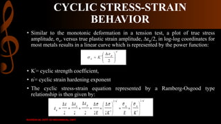
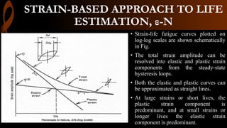
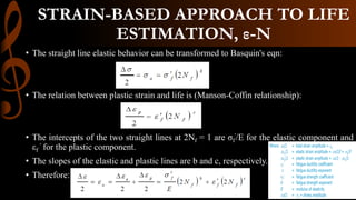


1) A monotonic tension test subjects a specimen to increasing tensile force until fracture to obtain its stress-strain behavior. For larger strains, true stress and strain must account for changes in specimen dimensions rather than engineering stress and strain. 2) Cyclic strain-controlled testing better characterizes fatigue behavior by directly controlling and measuring strain. Hysteresis loops provide the cyclic stress-strain response. 3) The strain-life approach relates the fatigue life of notched components to the life of unnotched specimens experiencing the same strain levels. It assesses fatigue damage directly based on local strain measurements.


