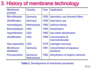
065048
Membrane Technology & Applications
Overview of Membrane
Science and Technology
Lecture 1
Prepared by
1/43
Dr. Nguyen Huu Hieu
Dept. of Chemical Process
& Equipment Engineering
Faculty of Chemical Engineering
Ho Chi Minh University of Technology
n h h i e u b k @ h c m u t . e d u . v n
Outline
1. Separation processes
2. Introduction to membrane processes
3. History of membrane technology
4. Definition of a membrane
5. Membrane processes
2/43
 Different types of process – different amount of energy
 Ex: production of fresh water from the sea:
I. Distillation: heat is supplied to the solution in such a way that
water distils off;
II. Freezing: the solution is cooled and pure ice is obtained;
III. Reverse osmosis (hyperfiltration): the solution is pressurised
allowing water molecules to pass through the membrane while
salt molecules are retained;
IV. Electrodialysis: an electric field is applied to a salt solution
between a number of charged membranes, and ions are forced
into certain compartments leaving water molecules in other
compartments;
V. Membrane distillation: heat is supplied to the solution causing
the transport of water vapour through the membrane.
1. Separation processes
3/43
molecular property separation process
Size filtration, microfiltration, ultrafiltration, dialysis,
gas separation, gel permeation
chromatography
vapour pressure distillation, membrane distillation
freezing point crystallisation
affinity extraction, adsorption, absorption,
hyperfiltration, gas separation, pervaporation,
affinity chromatography
charge ion exchange, electrodialysis, electrophoresis
density centrigugation
chemical nature complexation, liquid membranes
Table 1. Separation processes based on molecular properties
1. Separation processes
4/43
 Objectives of separation:
Concentration: the desired component is
present in a low concentration and solvent has
to be removed;
Purification: undesirable impurities have to be
removed;
Fractionation: a mixture must be separated into
two or more desired components.
1. Separation processes
5/43
 Membrane process: the feed stream is divided into
two streams
Retentate (concentrate) stream
Permeate stream
 Either the concentrate or permeate stream is the
product
1. Separation processes
6/43
 Membrane technology advantages:
 No specific chemical knowledge are needed
 Complex instrumentation is not required
 Constant attention is not required
 Basic concept is simple to understand
 Separation can be carried out continuously
 Energy consumption is generally low
 Membrane processes can easily be combined with other
separation processes
 Separation can be carried out under mild conditions
 Up-scaling is easy
 Membrane properties are variable and can be adjusted
 No additives are required
 Greater flexibility in designing systems
 Clean technology with operational ease
1. Separation processes
7/43
 Membrane technology disadvantages:
 Membranes are expensive
 Certain solvents can quickly and permanently destroy the
membrane
 Certain colloidal solids, especially graphite and residues from
vibratory deburring operations, can permanently foul the
membrane surface
 The energy cost is higher than chemical treatment, although
less than evaporation
 Oil emulsions are not "chemically separated," so secondary
oil recovery can be difficult
 Synthetics are not effectively treated by this method
 Concentration polarisation/membrane fouling;
 Low membrane lifetime;
 Generally low selectivity
1. Separation processes
8/43
 First generation membrane processes
Microfiltration (MF)
Ultrafiltration (UF)
Hyperfiltration (HF) or reverse osmosis (RO)
Electrodialysis (ED)
Nanofiltration (NF)
 Second generation membrane processes
Gas separation (GS)
Pervaporation (PV)
Membrane distillation (MD)
Separation by liquid membranes (LM)
2. Introduction to membrane processes
9/43
 Membrane: permselective barrier between two phases
 Phase 1: feed or upstream side phase, phase 2: permeate or
downstream side
 Separation: because the membrane can transport one
component from the feed mixture more readily than others
 Not ideal barrier
2. Introduction to membrane processes
10/43
 Efficiency of a given membrane:
 Selectivity
 Flow through the membrane (flux or permeation rate :
volume flowing through the membrane per unit area
and time)
 Volume flux
 Mass flux (density)
 Mole flux (molecular weight)
l m-2hr -1 =
(volume flux)
ρ kg m-2 hr -1 =
(mass flux)
ρ/M mole m-2 hr -1
(mole flux)
2. Introduction to membrane processes
11/43
 Selectivity of a given membrane:
 Retention (R)
 Separation factor (α)
 Retention: for aqueous mixtures, retention towards the solute
 Solute is retained while the solvent molecules pass freely
through the membrane
 C – solute concentration
 Dimensionless; 0%~100%
 Separation factor: for gas and organic liquids mixtures
 y – concentrations in permeate
x – concentrations in feed
 chosen such that α > 1
 αA/B: A permeates preferentially; αB/A: B
 αA/B =αB/A=1: no separation achieved
f
p
f
p
f
c
c
c
c
c
R 


 1
B
A
B
A
B
A
x
x
y
y
/
/
/ 

2. Introduction to membrane processes
12/43
Microfiltration Symmetric microporous, 100-10000 nm
Ultrafiltration Asymmetric microporous, 1-10 nm
Reverse Osmosis
(Hyperfiltration)
Asymmetric skin-type, 0.5-1.5 nm
Electrodialysis Cation and anion exchange membrane,
nonporous
Gas Separation Assymetric homogeneous polymer,
nonporous (or porous < 1nm)
Pervaporation Asymmetric homogenous polymer,
nonporous
Nanofiltration Thin-film membranes, order of
nanometers
2. Introduction to membrane processes
13/43
14/43
Microfiltration (MF)
 Most widely used membrane process with total sales greater than the
combined sales of all other membrane processes
 Separates suspended solids and some colloidal materials (>0.1 micron)
from a feed stream
 The concentrate requires periodic removal or cleaning to prevent the
eventual plugging of membrane feed passageways
 Pore size 0.1-10.0 microns
 Driving force: pressure difference
 approximately 10-500 kPa
 Two common forms:
 Crossflow separation: a fluid stream runs parallel to a membrane
 Dead-end (perpendicular) filtration: all of the fluid passes through
the membrane, and all of the particles that cannot fit through the
pores of the membrane are stopped
 Common applications: sterile filtration, clarification, etc
2. Introduction to membrane processes
15/43
Ultrafiltration (UF)
 Most commonly used to separate a solution that has a mixture of some
desirable components and some that are not desirable
 Separates colloidal material, emulsified oils, micro biological materials,
and large organic molecules
 Somewhat dependent on charge of the particle, and is much more
concerned with the size of the particle
 Pore sizes ranging from 10-1000 Angstroms (103-0.1 microns)
 most typical 0.005 micron
 Driving force: pressure differential
 approximately 0.1-1.0 MPa
 Performs feed clarification, concentration of rejected solutes and
fractionation of solutes
 Typically not effective at separating organic streams
 Common applications: removal and recovery of oils, surfactants and
paints from waste streams, clarification of wines and juices, and polishing
of ultra pure water for bacteria and particle removal
2. Introduction to membrane processes
16/43
Reverse Osmosis (RO) (Hyperfiltration)
 Specifically used for the separation of dissolved ions from water
(dissolved solids, bacteria, viruses, salts, proteins, and other germs)
 Charged ions and all other materials greater than or equal to 0.001
microns are rejected
 Essentially a pressure driven membrane diffusion process for
separating dissolved solutes
 Generally used for desalination seawater for its conversion into potable
water (purifying water)
 Involves no phase change and it is relatively a low energy process
 Smallest pore structure, 5-15 A0 (0.5 nm - 1.5 nm)
 allows only the smallest organic molecules and unchanged solutes
to pass through the semi-permeable membrane along with the
water
 >95-99% of inorganic salts and charged organics will also be
rejected by the membrane due to charge repulsion established at
the membrane surface
2. Introduction to membrane processes
17/43
Nanofiltration (NF)
 Uses membranes to preferentially separate different fluids or ions
 Not as fine a filtration process as reverse osmosis, but it also does not
require the same energy to perform the separation (“loose RO”)
 Uses a membrane that is partially permeable to perform the separation
(like in RO), but NF pores >> RO pores
 Can operate at much lower pressures, and passes some of the
inorganic salts due to larger pore size
 Advantage over RO: can typically operate at higher recoveries 
conserves total water usage due to a lower concentrate stream flow
rate
 Pore size is of order of nanometers
 Driving force: pressure difference
 Common applications: partial softening of feed water, removal of
contaminants from water or acid streams, and pretreatment for reverse
osmosis or other high purity systems
2. Introduction to membrane processes
18/43
Electrodialysis (ED)
 Electro-membrane process in which the ions are transported through a
membrane from one solution to another under the influence of an
electrical potential
 separation and concentration of salts, acids and bases from
aqueous solutions
 separation and concentration of monovalent ions from multiple
charged components
 separation of ionic compounds from uncharged molecules
 System consists of two kinds of membranes: cation and anion, placed
in an electric field
 cation-selective membrane permits only the cations, and anion-
selective membrane only the anions
 transport of ions across the membranes results in ion depiction in
some cells, and ion concentration in alternate ones
 Used widely for production of potable water from sea or brackish water,
electroplating rinse recovery, desalting of cheese whey, production of
ultrapure water etc.
2. Introduction to membrane processes
19/43
Gas Separation (GS)
 Separation of gas mixtures
 Technology is over ten years old and is proving to he one of the most
significant unit operations
 Mixed gas feed at an elevated pressure is passed across the surface of
a membrane that is selectively permeable to one component of the
feed partial separation
 Rate of permeation:
 proportional to pressure differential across the membrane
 inversely proportional to the membrane thickness
 proportional to the solubility of the gas in the membrane
 proportional to the diffusivity of gas through the membrane
 Driving force: concentration difference or Knusden flow
 Pore size: nonporous (or porous < 1 nanometer)
 Used for hydrogen separation and recovery, CO2 enhanced oil
recovery, natural gas processing, landfill gas upgrading, air separation,
nitrogen production, air dehydration, helium recovery etc.
2. Introduction to membrane processes
20/43
Pervaporation (PV)
 Separation of miscible liquids
 Liquid is maintained at atmospheric pressure on the feed side of the
membrane, and permeate is removed as a vapour because of a low
vapour pressure existing on the permeate side
 Three steps sequence:
 selective sorption of one of the components of the liquid into the
membrane on the feed side
 selective diffusion of this component across the membrane
 evaporation, as permeate vapour, into the partial vacuum applied to
the underside of the membrane
 Differs from all other membrane processes because of the phase
change of the permeate
 Transport is effected by maintaining a vapour pressure gradient across
the membrane
 Used for separation of ethanol-water mixture, solvent recovery,
separation of heat sensitive products etc.
2. Introduction to membrane processes
21/43
Membrane Distillation (MD)
 Separation of two liquids or solutions at different temperatures by a
porous membrane
 Liquids do not wet the membrane
 Non-wettable porous hydrophobic membrane
 Liquids differ in temperature  vapour pressure difference  vapour
molecules transport through the pores of the membrane from the high
vapour pressure side to the low
 evaporation on the high-temperature side
 transport of vapour molecules through the pores of membrane
 condensation on the low-temperature side
 Pore size: 0.2-1.0 μm
 Driving force: vapour pressure difference
 Only process where membrane is not directly involved in separation
2. Introduction to membrane processes
22/43
Figure 2. Batch membrane
filtration plant.
23/43
3. History of membrane technology
 Systematic studies of membrane phenomena can be
traced to the eighteenth century philosopher scientists
(1748: Abbe Nolet coined the word osmosis to describe
permeation of water through a diaphragm)
 19th till early 20th centries: membranes had no industrial or
commercial uses, but were used as laboratory tools
 1846 – discovery of nitrocellulose (gave growth to MF)
 1855 – cellulose nitrate membranes by Frick
 Membranes were developed for decades (mostly in
Germany)
 1906: Bechhold devised a technique to prepare
nitrocelluslose membranes of graded pore size by bubble-
test method
24/43
 1930s: microporous collodion membranes became commercially
available
 MF technology: 1950s
 First significant applications in the filtration of drinking water
samples at the end of World War II
 drinking water supplies were broken all over Europe 
urgent need for filters to test the water for safety
 research effort was sponsored by US army
 By 1960: elements of modern membrane science had been
developed
 used in only a few laboratories and small industrial
applications
 membranes: too unreliable, too slow, too unselective, too
expensive
3. History of membrane technology
25/43
 RO and UF came much later in time than MF, neither developed
from MF (UF derived from RO)
 RO: too small pores  too small throughput
 1959: RO membrane breakthrough – invention in UCLA of the
Loeb-Sourirajan membrane
 defect-free, high-flux, ultrathin
 ultrathin, selective surface film (<0.5 μm), which determines
the transport rate, supported by a microporous sublayer (50-
200 μm) that provides the mechanical strength
 first membranes had fluxes 10 times higher than any
membrane then available
 made RO a practical technology
3. History of membrane technology
26/43
 Henis and Tripodi made industrial GS economically feasible
 Placed a very thin homogeneous layer of a polymer with a
high gas permeability on top of an asymmetric membrane
 Pores in the top layer were filled  leek-free composite
membrane obtained
 Membrane distillation: hydrophobic porous membranes existed
for a long time, but the process has been applied on a big scale
only recently
 PV: developed recently
 attempt to commericialise PV in the late 50s was not very
successful
 subsequently, process-specific composite membranes were
developed for the dehydration of organic solvents
3. History of membrane technology
27/43
Membrane
process
Country Year Application
Microfiltration Germany 1920 laboratory use (bacteria filter)
Ultrafiltration Germany 1930 laboratory use
Hemodialysis Netherlands 1950 artificial kidney
Electrodialysis USA 1955 desalination
Hyperfiltration USA 1960 sea water desalination
Ultrafiltration USA 1960 concentration of
macromolecules
Gas separation USA 1979 hydrogen recovery
Membrane
distillation
Germany 1981 concentration of aqueous
solutions
Pervaporation Germany/
Netherlands
1982 dehydration of organic solvents
Table 2. Development of membrane processes
3. History of membrane technology
28/43
 Def.: selective barrier between two phases, the term ‘selective’
being inherent to a membrane or a membrane process
 Membrane:
 thick/thin
 homogeneous/heterogeneous
 active/passive transport
 pressure/concentration/temperature difference driven passive
transport
 natural/synthetic
 neutral/charged
 Classification by nature:
 biological or synthetic membranes
 biological: living and non-living
 synthetic: organic (polymeric or liquid) and inorganic
4. Definition of a membrane
29/43
 Classification by morphology or structure
 Symmetric and assymetric (isotropic/anisotropic)
 Symmetric membranes: uniform in composition and physical
nature across the cross-section of the membrane
 10-200 μm thick
 thickness decreases – permeation rate increases
 Assymetric membranes: non-uniform over the membrane
cross-section, typically consist of layers which vary in structure
and/or chemical composition
 0.1-0.5 μm thick dense layer supported by porous sublayer
50-150 μm thick
 high selectivity of dense membrane + high permeability of
thin membrane (ex.: Loeb-Sourirajan membranes)
 Composite membranes: skinned assymetric membranes
 top layer and sublayer originate from different polymeric
materials, each layer optimized independetly
4. Definition of a membrane
30/43
Figure 3. Schematic
representation of
membrane cross
sections.
4. Definition of a membrane
31/43
(a) (b)
Figure 4. (a) Cross-section of anisotropic microporous membrane,
(b) Cross-section of a thin-film composite membrane.
4. Definition of a membrane
32/43
 Electrically charged membranes
necessarily ion-exchange membranes
consisting of highly swollen gels carrying fixed
positive or negative charges
 Liquid membranes
utilizes a carrier to selectively transport
components such as metal ions at relatively
high rate across the membrane interface
4. Definition of a membrane
33/43
 Isotropic and anisotropic membranes refer to flat sheet configurations
 Membranes can also be produced as hollow fibers
 isotropic or anisotropic
 dense or porous
 Common fibers used in industry: anisotropic with a dense outer layer
around a porous tube (Figure 5)
 Advantage: more surface area per unit volume than flat sheet
membranes
Figure 5. Hollow fiber
cross-section.
4. Definition of a membrane
34/43
 Membranes can be configured in various ways:
 Round tubes with approximately 0.5" or 1"
internal diameter, which can last from 3 to 8 years
 Hollow fibers with an approximate internal
diameter of 0.030", which can last from 1 to 2
years
 Flat sheets wrapped in a spiral configuration,
lasting from 3 to 8 years
 Flat sheets that are vibrated or turbulated with
mechanical "wipers," lasting from 3 to 8 years
4. Definition of a membrane
35/43
 Particular separation – particular membrane
 Difference in physical and/or chemical properties between
membrane and permeating components
  membrane’s ability to transport one component more
readily than other
 transport is the result of driving force acting on individual
components in the feed
 Often permeation rate is proportional to the driving force:
 A – phenomenological coefficient
 dX/dx – driving force: gradient of X (temperature, concentration,
pressure) along x-coordinate perpendicular to the transport barrier
5. Membrane processes
dx
dX
A
J 

36/43
mass flux Jm = -D dC/dx (Fick)
volume flux Jν = -Lp dP/dx (Darcy)
heat flux Jh = - a dT/dx (Fourier)
momentum flux Jn = - ν dv/dx (Newton)
electrical flux Ji = -1/R dE/dx (Ohm)
 Phenomenological coefficient:
 Diffusion coefficient (D)
 Permeability coefficient (lp)
 Thermal diffusivity (a)
 Kinematic viscosity (ν)
 Electrical conductivity (1/R)
Table 3. Phenomenological equations
5. Membrane processes
37/43
 Pure permeate stream: linear relations to describe the transport
 Two/more components permeate simultaneously: coupling
phenomena may occur
 non-equilibrium thermodynamics
Figure 6. Schematic representation of
phases divided by a membrane
5. Membrane processes
38/43
 Factors determining selectivity and flux:
 driving force (gradients in pressure, concentration, electrical
potential or temperature)
 membrane itself
 nature of membrane determines the type of application
 If particles with d>100 nm to be retained (MF):
 possible to use rather open membrane structure
 low hydrodynamic resistance
 small driving forces (low hydrostatic pressures)
 high fluxes
 To separate macromolecules (molecular weight of 104-106) from an
aqueous solution (UF)
 more dense membrane structure
 increased hydrodynamic resistance
 greater applied pressure
5. Membrane processes
39/43
 To separate low molecular weight components of roughly equal size
from each other (RO)
 very dense (assymetric) membrane
  very high hydrodynamic resistance
 MF  UF  RO :
 hydrodynamic pressure increases  higher driving forces are
needed
 product flux and retained molecules size decreases
 MF: ΔP ≈ 0.1 to 0.2 bar
flux > 0.5 m3m-2day-1bar-1
 UF: ΔP ≈ 1 to 5 bar
flux ≈ 0.1 – 0.5 m3m-2day-1bar-1
 RO: ΔP ≈ 10 to 100 bar
flux < 0.05 m3m-2day-1bar-1
5. Membrane processes
40/43
Figure 7. General flow
patterns of the
various membrane
separation systems
used in diary industry
5. Membrane
processes
41/43
Microfiltration Symmetric
microporous , 100-
10000 nm
L/L Hydrostatic pressure
difference 10-500 kPa
Ultrafiltration Asymmetric
microporous, 1-10 nm
L/L Hydrostatic pressure
difference 0.1-1.0 Mpa
Reverse Osmosis
(Hyperfiltration)
Asymmetric skin-type,
0.5-1.5 nm
L/L Hydrostatic pressure
difference 2-10 Mpa
Electrodialysis Cation and anion
exchange membrane,
nonporous
L/L Electrical potential
gradient
Gas Separation Nonporous (or porous
< 1nm)
G/G Hydrostatic pressure and
concentration gradients
Pervaporation Asymmetric
homogenous polymer,
nonporous
L/G Vapour pressure gradient
Nanofiltration Thin-film membranes,
order of nanometers
L/L 9.3-15.9 bar
5. Membrane processes
42/43
5. Membrane processes
43/43
Thank You
Natalia Yakunina

MTA_C1.ppt

  • 1.
    065048 Membrane Technology &Applications Overview of Membrane Science and Technology Lecture 1 Prepared by 1/43 Dr. Nguyen Huu Hieu Dept. of Chemical Process & Equipment Engineering Faculty of Chemical Engineering Ho Chi Minh University of Technology n h h i e u b k @ h c m u t . e d u . v n
  • 2.
    Outline 1. Separation processes 2.Introduction to membrane processes 3. History of membrane technology 4. Definition of a membrane 5. Membrane processes 2/43
  • 3.
     Different typesof process – different amount of energy  Ex: production of fresh water from the sea: I. Distillation: heat is supplied to the solution in such a way that water distils off; II. Freezing: the solution is cooled and pure ice is obtained; III. Reverse osmosis (hyperfiltration): the solution is pressurised allowing water molecules to pass through the membrane while salt molecules are retained; IV. Electrodialysis: an electric field is applied to a salt solution between a number of charged membranes, and ions are forced into certain compartments leaving water molecules in other compartments; V. Membrane distillation: heat is supplied to the solution causing the transport of water vapour through the membrane. 1. Separation processes 3/43
  • 4.
    molecular property separationprocess Size filtration, microfiltration, ultrafiltration, dialysis, gas separation, gel permeation chromatography vapour pressure distillation, membrane distillation freezing point crystallisation affinity extraction, adsorption, absorption, hyperfiltration, gas separation, pervaporation, affinity chromatography charge ion exchange, electrodialysis, electrophoresis density centrigugation chemical nature complexation, liquid membranes Table 1. Separation processes based on molecular properties 1. Separation processes 4/43
  • 5.
     Objectives ofseparation: Concentration: the desired component is present in a low concentration and solvent has to be removed; Purification: undesirable impurities have to be removed; Fractionation: a mixture must be separated into two or more desired components. 1. Separation processes 5/43
  • 6.
     Membrane process:the feed stream is divided into two streams Retentate (concentrate) stream Permeate stream  Either the concentrate or permeate stream is the product 1. Separation processes 6/43
  • 7.
     Membrane technologyadvantages:  No specific chemical knowledge are needed  Complex instrumentation is not required  Constant attention is not required  Basic concept is simple to understand  Separation can be carried out continuously  Energy consumption is generally low  Membrane processes can easily be combined with other separation processes  Separation can be carried out under mild conditions  Up-scaling is easy  Membrane properties are variable and can be adjusted  No additives are required  Greater flexibility in designing systems  Clean technology with operational ease 1. Separation processes 7/43
  • 8.
     Membrane technologydisadvantages:  Membranes are expensive  Certain solvents can quickly and permanently destroy the membrane  Certain colloidal solids, especially graphite and residues from vibratory deburring operations, can permanently foul the membrane surface  The energy cost is higher than chemical treatment, although less than evaporation  Oil emulsions are not "chemically separated," so secondary oil recovery can be difficult  Synthetics are not effectively treated by this method  Concentration polarisation/membrane fouling;  Low membrane lifetime;  Generally low selectivity 1. Separation processes 8/43
  • 9.
     First generationmembrane processes Microfiltration (MF) Ultrafiltration (UF) Hyperfiltration (HF) or reverse osmosis (RO) Electrodialysis (ED) Nanofiltration (NF)  Second generation membrane processes Gas separation (GS) Pervaporation (PV) Membrane distillation (MD) Separation by liquid membranes (LM) 2. Introduction to membrane processes 9/43
  • 10.
     Membrane: permselectivebarrier between two phases  Phase 1: feed or upstream side phase, phase 2: permeate or downstream side  Separation: because the membrane can transport one component from the feed mixture more readily than others  Not ideal barrier 2. Introduction to membrane processes 10/43
  • 11.
     Efficiency ofa given membrane:  Selectivity  Flow through the membrane (flux or permeation rate : volume flowing through the membrane per unit area and time)  Volume flux  Mass flux (density)  Mole flux (molecular weight) l m-2hr -1 = (volume flux) ρ kg m-2 hr -1 = (mass flux) ρ/M mole m-2 hr -1 (mole flux) 2. Introduction to membrane processes 11/43
  • 12.
     Selectivity ofa given membrane:  Retention (R)  Separation factor (α)  Retention: for aqueous mixtures, retention towards the solute  Solute is retained while the solvent molecules pass freely through the membrane  C – solute concentration  Dimensionless; 0%~100%  Separation factor: for gas and organic liquids mixtures  y – concentrations in permeate x – concentrations in feed  chosen such that α > 1  αA/B: A permeates preferentially; αB/A: B  αA/B =αB/A=1: no separation achieved f p f p f c c c c c R     1 B A B A B A x x y y / / /   2. Introduction to membrane processes 12/43
  • 13.
    Microfiltration Symmetric microporous,100-10000 nm Ultrafiltration Asymmetric microporous, 1-10 nm Reverse Osmosis (Hyperfiltration) Asymmetric skin-type, 0.5-1.5 nm Electrodialysis Cation and anion exchange membrane, nonporous Gas Separation Assymetric homogeneous polymer, nonporous (or porous < 1nm) Pervaporation Asymmetric homogenous polymer, nonporous Nanofiltration Thin-film membranes, order of nanometers 2. Introduction to membrane processes 13/43
  • 14.
  • 15.
    Microfiltration (MF)  Mostwidely used membrane process with total sales greater than the combined sales of all other membrane processes  Separates suspended solids and some colloidal materials (>0.1 micron) from a feed stream  The concentrate requires periodic removal or cleaning to prevent the eventual plugging of membrane feed passageways  Pore size 0.1-10.0 microns  Driving force: pressure difference  approximately 10-500 kPa  Two common forms:  Crossflow separation: a fluid stream runs parallel to a membrane  Dead-end (perpendicular) filtration: all of the fluid passes through the membrane, and all of the particles that cannot fit through the pores of the membrane are stopped  Common applications: sterile filtration, clarification, etc 2. Introduction to membrane processes 15/43
  • 16.
    Ultrafiltration (UF)  Mostcommonly used to separate a solution that has a mixture of some desirable components and some that are not desirable  Separates colloidal material, emulsified oils, micro biological materials, and large organic molecules  Somewhat dependent on charge of the particle, and is much more concerned with the size of the particle  Pore sizes ranging from 10-1000 Angstroms (103-0.1 microns)  most typical 0.005 micron  Driving force: pressure differential  approximately 0.1-1.0 MPa  Performs feed clarification, concentration of rejected solutes and fractionation of solutes  Typically not effective at separating organic streams  Common applications: removal and recovery of oils, surfactants and paints from waste streams, clarification of wines and juices, and polishing of ultra pure water for bacteria and particle removal 2. Introduction to membrane processes 16/43
  • 17.
    Reverse Osmosis (RO)(Hyperfiltration)  Specifically used for the separation of dissolved ions from water (dissolved solids, bacteria, viruses, salts, proteins, and other germs)  Charged ions and all other materials greater than or equal to 0.001 microns are rejected  Essentially a pressure driven membrane diffusion process for separating dissolved solutes  Generally used for desalination seawater for its conversion into potable water (purifying water)  Involves no phase change and it is relatively a low energy process  Smallest pore structure, 5-15 A0 (0.5 nm - 1.5 nm)  allows only the smallest organic molecules and unchanged solutes to pass through the semi-permeable membrane along with the water  >95-99% of inorganic salts and charged organics will also be rejected by the membrane due to charge repulsion established at the membrane surface 2. Introduction to membrane processes 17/43
  • 18.
    Nanofiltration (NF)  Usesmembranes to preferentially separate different fluids or ions  Not as fine a filtration process as reverse osmosis, but it also does not require the same energy to perform the separation (“loose RO”)  Uses a membrane that is partially permeable to perform the separation (like in RO), but NF pores >> RO pores  Can operate at much lower pressures, and passes some of the inorganic salts due to larger pore size  Advantage over RO: can typically operate at higher recoveries  conserves total water usage due to a lower concentrate stream flow rate  Pore size is of order of nanometers  Driving force: pressure difference  Common applications: partial softening of feed water, removal of contaminants from water or acid streams, and pretreatment for reverse osmosis or other high purity systems 2. Introduction to membrane processes 18/43
  • 19.
    Electrodialysis (ED)  Electro-membraneprocess in which the ions are transported through a membrane from one solution to another under the influence of an electrical potential  separation and concentration of salts, acids and bases from aqueous solutions  separation and concentration of monovalent ions from multiple charged components  separation of ionic compounds from uncharged molecules  System consists of two kinds of membranes: cation and anion, placed in an electric field  cation-selective membrane permits only the cations, and anion- selective membrane only the anions  transport of ions across the membranes results in ion depiction in some cells, and ion concentration in alternate ones  Used widely for production of potable water from sea or brackish water, electroplating rinse recovery, desalting of cheese whey, production of ultrapure water etc. 2. Introduction to membrane processes 19/43
  • 20.
    Gas Separation (GS) Separation of gas mixtures  Technology is over ten years old and is proving to he one of the most significant unit operations  Mixed gas feed at an elevated pressure is passed across the surface of a membrane that is selectively permeable to one component of the feed partial separation  Rate of permeation:  proportional to pressure differential across the membrane  inversely proportional to the membrane thickness  proportional to the solubility of the gas in the membrane  proportional to the diffusivity of gas through the membrane  Driving force: concentration difference or Knusden flow  Pore size: nonporous (or porous < 1 nanometer)  Used for hydrogen separation and recovery, CO2 enhanced oil recovery, natural gas processing, landfill gas upgrading, air separation, nitrogen production, air dehydration, helium recovery etc. 2. Introduction to membrane processes 20/43
  • 21.
    Pervaporation (PV)  Separationof miscible liquids  Liquid is maintained at atmospheric pressure on the feed side of the membrane, and permeate is removed as a vapour because of a low vapour pressure existing on the permeate side  Three steps sequence:  selective sorption of one of the components of the liquid into the membrane on the feed side  selective diffusion of this component across the membrane  evaporation, as permeate vapour, into the partial vacuum applied to the underside of the membrane  Differs from all other membrane processes because of the phase change of the permeate  Transport is effected by maintaining a vapour pressure gradient across the membrane  Used for separation of ethanol-water mixture, solvent recovery, separation of heat sensitive products etc. 2. Introduction to membrane processes 21/43
  • 22.
    Membrane Distillation (MD) Separation of two liquids or solutions at different temperatures by a porous membrane  Liquids do not wet the membrane  Non-wettable porous hydrophobic membrane  Liquids differ in temperature  vapour pressure difference  vapour molecules transport through the pores of the membrane from the high vapour pressure side to the low  evaporation on the high-temperature side  transport of vapour molecules through the pores of membrane  condensation on the low-temperature side  Pore size: 0.2-1.0 μm  Driving force: vapour pressure difference  Only process where membrane is not directly involved in separation 2. Introduction to membrane processes 22/43
  • 23.
    Figure 2. Batchmembrane filtration plant. 23/43
  • 24.
    3. History ofmembrane technology  Systematic studies of membrane phenomena can be traced to the eighteenth century philosopher scientists (1748: Abbe Nolet coined the word osmosis to describe permeation of water through a diaphragm)  19th till early 20th centries: membranes had no industrial or commercial uses, but were used as laboratory tools  1846 – discovery of nitrocellulose (gave growth to MF)  1855 – cellulose nitrate membranes by Frick  Membranes were developed for decades (mostly in Germany)  1906: Bechhold devised a technique to prepare nitrocelluslose membranes of graded pore size by bubble- test method 24/43
  • 25.
     1930s: microporouscollodion membranes became commercially available  MF technology: 1950s  First significant applications in the filtration of drinking water samples at the end of World War II  drinking water supplies were broken all over Europe  urgent need for filters to test the water for safety  research effort was sponsored by US army  By 1960: elements of modern membrane science had been developed  used in only a few laboratories and small industrial applications  membranes: too unreliable, too slow, too unselective, too expensive 3. History of membrane technology 25/43
  • 26.
     RO andUF came much later in time than MF, neither developed from MF (UF derived from RO)  RO: too small pores  too small throughput  1959: RO membrane breakthrough – invention in UCLA of the Loeb-Sourirajan membrane  defect-free, high-flux, ultrathin  ultrathin, selective surface film (<0.5 μm), which determines the transport rate, supported by a microporous sublayer (50- 200 μm) that provides the mechanical strength  first membranes had fluxes 10 times higher than any membrane then available  made RO a practical technology 3. History of membrane technology 26/43
  • 27.
     Henis andTripodi made industrial GS economically feasible  Placed a very thin homogeneous layer of a polymer with a high gas permeability on top of an asymmetric membrane  Pores in the top layer were filled  leek-free composite membrane obtained  Membrane distillation: hydrophobic porous membranes existed for a long time, but the process has been applied on a big scale only recently  PV: developed recently  attempt to commericialise PV in the late 50s was not very successful  subsequently, process-specific composite membranes were developed for the dehydration of organic solvents 3. History of membrane technology 27/43
  • 28.
    Membrane process Country Year Application MicrofiltrationGermany 1920 laboratory use (bacteria filter) Ultrafiltration Germany 1930 laboratory use Hemodialysis Netherlands 1950 artificial kidney Electrodialysis USA 1955 desalination Hyperfiltration USA 1960 sea water desalination Ultrafiltration USA 1960 concentration of macromolecules Gas separation USA 1979 hydrogen recovery Membrane distillation Germany 1981 concentration of aqueous solutions Pervaporation Germany/ Netherlands 1982 dehydration of organic solvents Table 2. Development of membrane processes 3. History of membrane technology 28/43
  • 29.
     Def.: selectivebarrier between two phases, the term ‘selective’ being inherent to a membrane or a membrane process  Membrane:  thick/thin  homogeneous/heterogeneous  active/passive transport  pressure/concentration/temperature difference driven passive transport  natural/synthetic  neutral/charged  Classification by nature:  biological or synthetic membranes  biological: living and non-living  synthetic: organic (polymeric or liquid) and inorganic 4. Definition of a membrane 29/43
  • 30.
     Classification bymorphology or structure  Symmetric and assymetric (isotropic/anisotropic)  Symmetric membranes: uniform in composition and physical nature across the cross-section of the membrane  10-200 μm thick  thickness decreases – permeation rate increases  Assymetric membranes: non-uniform over the membrane cross-section, typically consist of layers which vary in structure and/or chemical composition  0.1-0.5 μm thick dense layer supported by porous sublayer 50-150 μm thick  high selectivity of dense membrane + high permeability of thin membrane (ex.: Loeb-Sourirajan membranes)  Composite membranes: skinned assymetric membranes  top layer and sublayer originate from different polymeric materials, each layer optimized independetly 4. Definition of a membrane 30/43
  • 31.
    Figure 3. Schematic representationof membrane cross sections. 4. Definition of a membrane 31/43
  • 32.
    (a) (b) Figure 4.(a) Cross-section of anisotropic microporous membrane, (b) Cross-section of a thin-film composite membrane. 4. Definition of a membrane 32/43
  • 33.
     Electrically chargedmembranes necessarily ion-exchange membranes consisting of highly swollen gels carrying fixed positive or negative charges  Liquid membranes utilizes a carrier to selectively transport components such as metal ions at relatively high rate across the membrane interface 4. Definition of a membrane 33/43
  • 34.
     Isotropic andanisotropic membranes refer to flat sheet configurations  Membranes can also be produced as hollow fibers  isotropic or anisotropic  dense or porous  Common fibers used in industry: anisotropic with a dense outer layer around a porous tube (Figure 5)  Advantage: more surface area per unit volume than flat sheet membranes Figure 5. Hollow fiber cross-section. 4. Definition of a membrane 34/43
  • 35.
     Membranes canbe configured in various ways:  Round tubes with approximately 0.5" or 1" internal diameter, which can last from 3 to 8 years  Hollow fibers with an approximate internal diameter of 0.030", which can last from 1 to 2 years  Flat sheets wrapped in a spiral configuration, lasting from 3 to 8 years  Flat sheets that are vibrated or turbulated with mechanical "wipers," lasting from 3 to 8 years 4. Definition of a membrane 35/43
  • 36.
     Particular separation– particular membrane  Difference in physical and/or chemical properties between membrane and permeating components   membrane’s ability to transport one component more readily than other  transport is the result of driving force acting on individual components in the feed  Often permeation rate is proportional to the driving force:  A – phenomenological coefficient  dX/dx – driving force: gradient of X (temperature, concentration, pressure) along x-coordinate perpendicular to the transport barrier 5. Membrane processes dx dX A J   36/43
  • 37.
    mass flux Jm= -D dC/dx (Fick) volume flux Jν = -Lp dP/dx (Darcy) heat flux Jh = - a dT/dx (Fourier) momentum flux Jn = - ν dv/dx (Newton) electrical flux Ji = -1/R dE/dx (Ohm)  Phenomenological coefficient:  Diffusion coefficient (D)  Permeability coefficient (lp)  Thermal diffusivity (a)  Kinematic viscosity (ν)  Electrical conductivity (1/R) Table 3. Phenomenological equations 5. Membrane processes 37/43
  • 38.
     Pure permeatestream: linear relations to describe the transport  Two/more components permeate simultaneously: coupling phenomena may occur  non-equilibrium thermodynamics Figure 6. Schematic representation of phases divided by a membrane 5. Membrane processes 38/43
  • 39.
     Factors determiningselectivity and flux:  driving force (gradients in pressure, concentration, electrical potential or temperature)  membrane itself  nature of membrane determines the type of application  If particles with d>100 nm to be retained (MF):  possible to use rather open membrane structure  low hydrodynamic resistance  small driving forces (low hydrostatic pressures)  high fluxes  To separate macromolecules (molecular weight of 104-106) from an aqueous solution (UF)  more dense membrane structure  increased hydrodynamic resistance  greater applied pressure 5. Membrane processes 39/43
  • 40.
     To separatelow molecular weight components of roughly equal size from each other (RO)  very dense (assymetric) membrane   very high hydrodynamic resistance  MF  UF  RO :  hydrodynamic pressure increases  higher driving forces are needed  product flux and retained molecules size decreases  MF: ΔP ≈ 0.1 to 0.2 bar flux > 0.5 m3m-2day-1bar-1  UF: ΔP ≈ 1 to 5 bar flux ≈ 0.1 – 0.5 m3m-2day-1bar-1  RO: ΔP ≈ 10 to 100 bar flux < 0.05 m3m-2day-1bar-1 5. Membrane processes 40/43
  • 41.
    Figure 7. Generalflow patterns of the various membrane separation systems used in diary industry 5. Membrane processes 41/43
  • 42.
    Microfiltration Symmetric microporous ,100- 10000 nm L/L Hydrostatic pressure difference 10-500 kPa Ultrafiltration Asymmetric microporous, 1-10 nm L/L Hydrostatic pressure difference 0.1-1.0 Mpa Reverse Osmosis (Hyperfiltration) Asymmetric skin-type, 0.5-1.5 nm L/L Hydrostatic pressure difference 2-10 Mpa Electrodialysis Cation and anion exchange membrane, nonporous L/L Electrical potential gradient Gas Separation Nonporous (or porous < 1nm) G/G Hydrostatic pressure and concentration gradients Pervaporation Asymmetric homogenous polymer, nonporous L/G Vapour pressure gradient Nanofiltration Thin-film membranes, order of nanometers L/L 9.3-15.9 bar 5. Membrane processes 42/43
  • 43.
  • 44.

Editor's Notes

  • #4 Hyper: siêu
  • #18 Repulsion: sự đẩy ngược