Downloaded 28 times


![WinProladder
Software
Step 1: Execute the WinProlad.exe program .
Step 2: Select [File] [New Project] from the function
toolbar using your mouse, or press “Ctrl” + “N” on your
keyboard, and the [New Project] window will appear
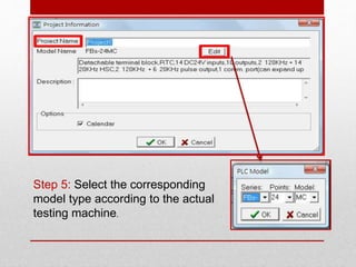
Step 3: Enter “Test example” into the [Project Name]
field.
Step 4: Click on the Edit button to enter the PLC
model type selection screen.
Create a Project](https://image.slidesharecdn.com/plcfatek-190916150630/85/Plc-fatek-15-320.jpg)
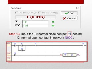
![Step 11: move your cursor to the in the component
tray and click on it, now a cursor in the shape of a T
should appear. Left click on your mouse and the
following dialog box window should appear.
Step 12: After you input “0”, use your mouse or the
“Down” arrow key to move the cursor to the [PV] field
and input “100” and then press “Enter” or click on the
“OK” button using your mouse , now you have
completed the input of the T0 timer function.](https://image.slidesharecdn.com/plcfatek-190916150630/85/Plc-fatek-24-320.jpg)
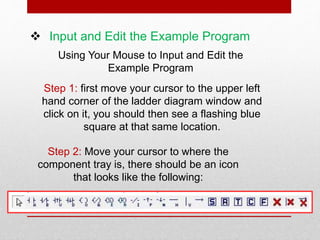
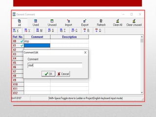
![Annotating the Example Program
Step 1: Select [Project] [Comments] [Element
Comment] in the functions toolbar; or select the
from the expanded menu; or click on
icon in the tool bar, and the following window will
appear:](https://image.slidesharecdn.com/plcfatek-190916150630/85/Plc-fatek-26-320.jpg)
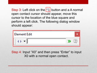
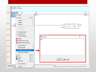
![Step 2: Now we will proceed with [Network Comment],
use your mouse to move the cursor to the network that
you wish to annotate, right click on the mouse to call out
the popup function menu, then click on
[Network Comment], and then a window for entering
network annotations will appear.](https://image.slidesharecdn.com/plcfatek-190916150630/85/Plc-fatek-28-320.jpg)
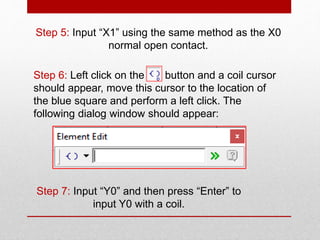
![Step 3: Now we will proceed with [Program Unit
Comment], use your mouse to move the cursor inside
the program unit that you wish to annotate, right click
on your mouse to bring out the popup function menu
and then select [Program Unit Comment]; a window
will appear for you to input through.](https://image.slidesharecdn.com/plcfatek-190916150630/85/Plc-fatek-29-320.jpg)
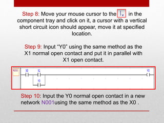
![Step 4: Save the previous input content to project files.
Use the [File] [Save] in the function toolbar or
press “Ctrl+“S”.](https://image.slidesharecdn.com/plcfatek-190916150630/85/Plc-fatek-31-320.jpg)
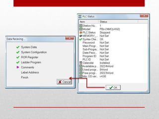
![Testing and Debugging
Step 1: First save the previously entered program
code to the PLC, select [File] [Save As] [To PLC]
or from the function toolbar and [PLC] [On-Line]
dialog box will appear, as shown below:](https://image.slidesharecdn.com/plcfatek-190916150630/85/Plc-fatek-32-320.jpg)
![Step 2: After the previous step is completed, the
content in the PLC will be the same as that in the
project file, so that now you can take advantage of
the [PLC] [Run PLC] in the function toolbar; or
enter the hotkey “F9” to give a command to the PLC
to execute the program. You can also select [PLC]
[Stop PLC] in the function toolbar; or enter the “Ctrl” +
“F9” hotkey to give a command to the PLC to stop
execution of the program.
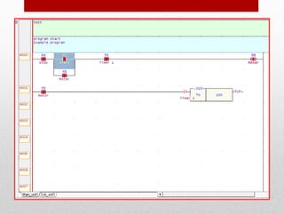
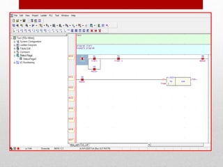
Step 3: When the PLC executes, the cascaded
program window will be under the following
condition:](https://image.slidesharecdn.com/plcfatek-190916150630/85/Plc-fatek-34-320.jpg)
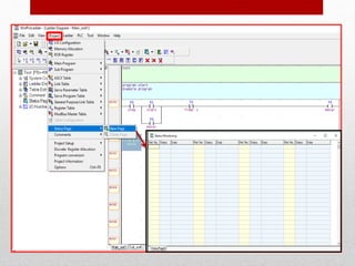
![Step 4: Use the [Status Page] for testing, first open an
empty status monitoring page by doing the following:
Select [Project] [Status Page] [New Page] from the
function toolbar; or use your mouse to double-click on
the icon in the project window; or use your mouse to
select the icon in the function toolbar and then select to
open a new monitoring page.
Once you have completed the above procedures,
a dialog box will appear, please enter
“StatusPage0” in the [Status Page Name] field, then
press “OK” and the following window will appear:](https://image.slidesharecdn.com/plcfatek-190916150630/85/Plc-fatek-36-320.jpg)
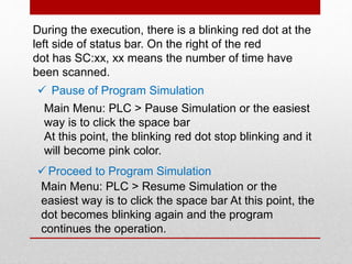
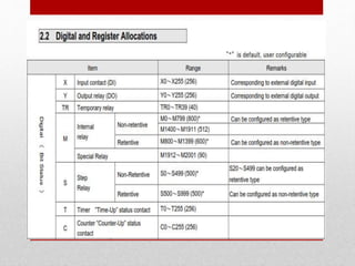
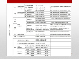
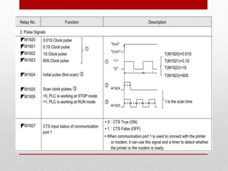
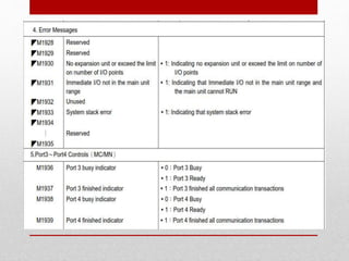


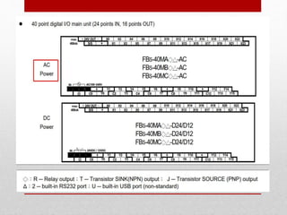
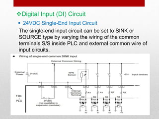
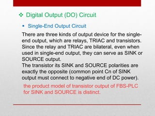
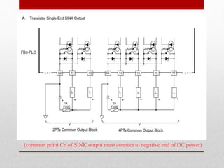
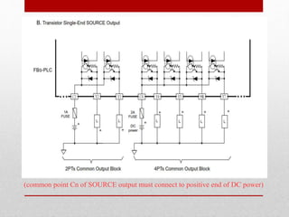
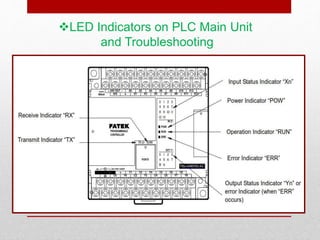
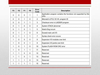
This document provides information about PLC FATEK (FBs-40MAT) including descriptions of its digital input and output circuits, LED indicators, communication ports, input and output status indicators, and how to create and test a sample ladder logic program using WinProladder software. It describes how to input and annotate a sample program testing inputs X0 and X1 to control output Y0 using a T0 timer, save the program to the PLC, run and debug the program simulation, and monitor I/O status.