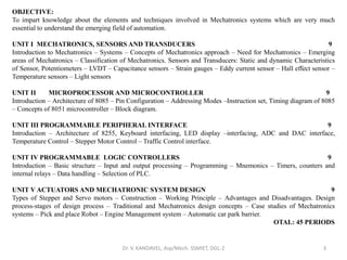
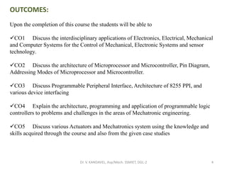
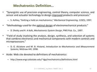
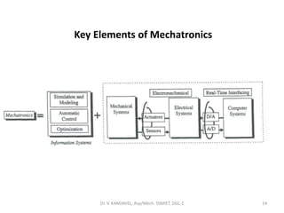
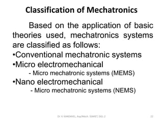
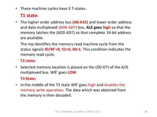
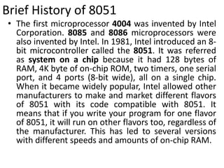
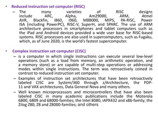
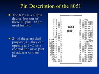
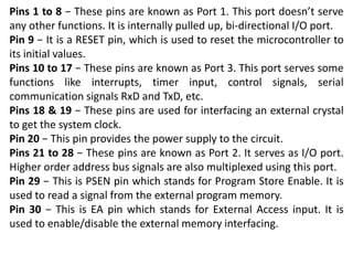
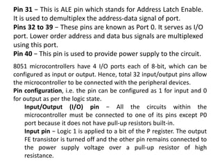
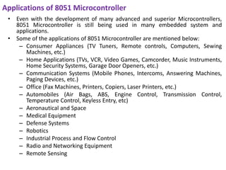
This document outlines the course objectives and content for a mechatronics course. It includes 5 units that cover topics such as mechatronics systems, sensors and transducers, microprocessors and microcontrollers, programmable peripheral interfaces, programmable logic controllers, and actuators and mechatronic system design. The course aims to impart knowledge of elements and techniques involved in mechatronic systems to understand the emerging field of automation.

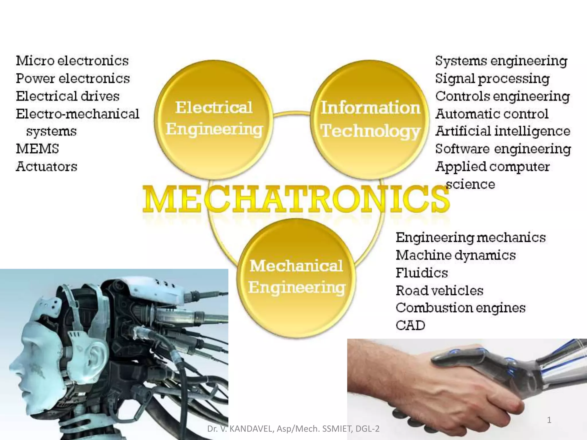
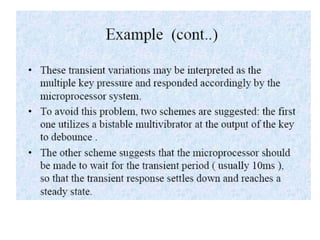
![Mechatronics Definition…
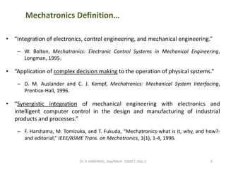
• “The name [mechatronics] was coined by Ko Kikuchi, now president of Yasakawa
Electric Co., Chiyoda-Ku, Tokyo.”
– R. Comerford, “Mecha … what?” IEEE Spectrum, 31(8), 46-49, 1994.
• “The word, mechatronics is composed of mecha from mechanics and tronics
from electronics. In other words, technologies and developed products will be
incorporating electronics more and more into mechanisms, intimately and
organically, and making it impossible to tell where one ends and the other
begins.”
– T. Mori, “Mechatronics,” Yasakawa Internal Trademark Application Memo, 21.131.01,
July 12, 1969.
Mechatronics
mecha
tronicsEletronics
Mechanics
8Dr. V. KANDAVEL, Asp/Mech. SSMIET, DGL-2](https://image.slidesharecdn.com/1-201209090340/85/ME8791-Mechatronics-vk-ssm-8-320.jpg)


![Electrical Actuation Systems
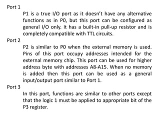
A actuator which can receive electrical energy
for motion is known as electrical actuator.
• Mechanical Switches :
– Relays
• Solid state switches:
– Diodes
– Thyristors (or) SCR [Silicon Controlled Rectifier]
– TRIAC (Triode for Alternating Current)
– Bipolar Transistors
– MOSFETS (Metal Oxide Field Effect Transistor)
254Dr. V. KANDAVEL, Asp/Mech. SSMIET, DGL-2](https://image.slidesharecdn.com/1-201209090340/85/ME8791-Mechatronics-vk-ssm-254-320.jpg)