Downloaded 15 times

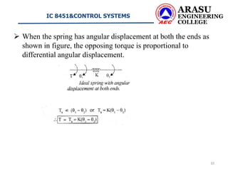
![ MECHANICAL ROTATIONAL SYSTEMS
The model of rotational mechanical systems can be obtained by
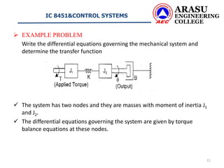
using three elements, moment of inertia [J] of mass, dash-pot with
rotational frictional coefficient [B] and torsional spring with
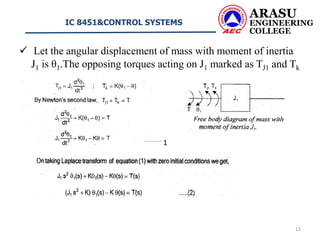
stiffness [K].
The weight of the rotational mechanical system is represented by the
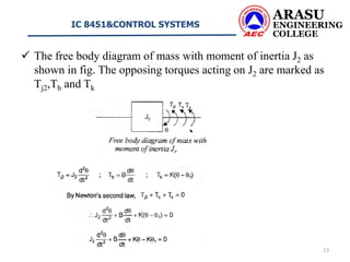
moment of inertia of the mass.
The moment of inertia of the system or body is considered to be
concentrated at the centre of gravity of the body.
The elastic deformation of the body can be represented by a spring
(torsional spring).
The friction existing in rotational mechanical system can be
represented by the dash-pot.
The dash-pot is a piston rotating inside a cylinder filled with
viscous fluid.
ARASU
ENGINEERING
COLLEGE
IC 8451&CONTROL SYSTEMS
3](https://image.slidesharecdn.com/mechanicalrotationalsystemtransferfunction-210209040816/85/Transfer-function-of-Mechanical-rotational-system-3-320.jpg)
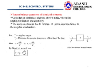
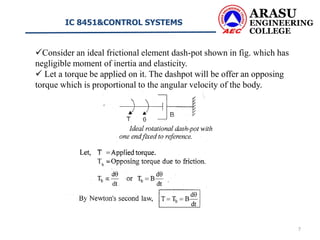
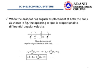
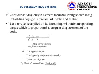
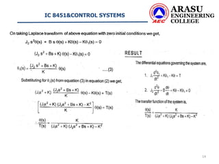
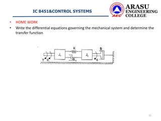

This document discusses rotational mechanical systems and their modeling. It describes how rotational systems can be modeled using three elements: moment of inertia to represent mass, a dashpot to represent friction, and a torsional spring to represent elasticity. It provides the torque balance equations for idealized elements of mass, friction, and elasticity. As an example, it analyzes a two-mass rotational system and derives the differential equations governing its motion and determines its transfer function.