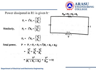
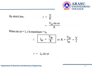
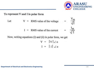
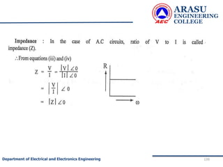
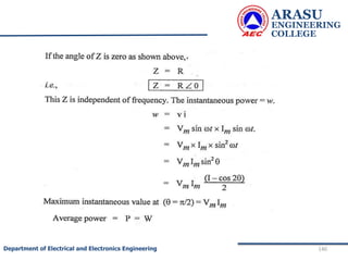
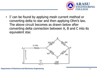
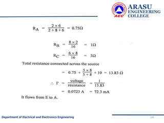
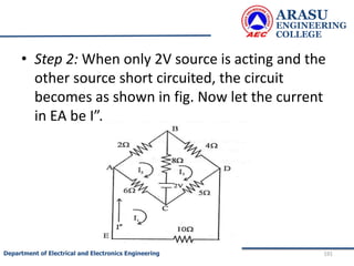
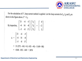
Downloaded 27 times


![ARASU
ENGINEERING
COLLEGE
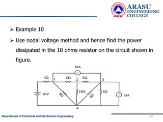
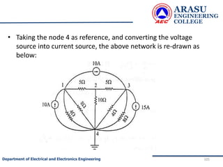
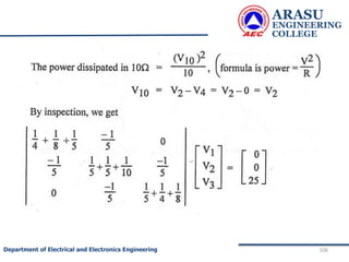
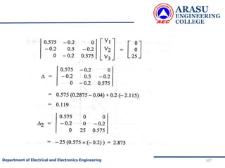
78
Department of Electrical and Electronics Engineering
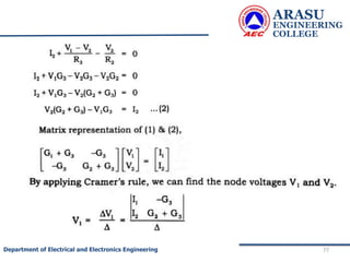
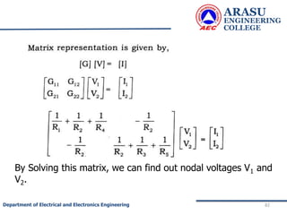
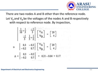
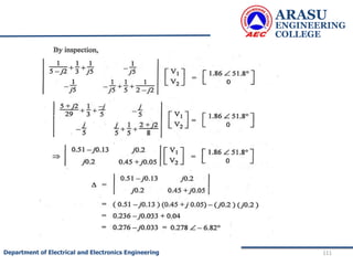
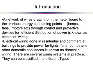
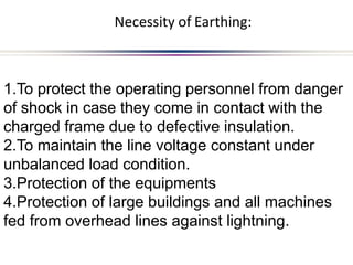
The generalized node equations can be written as
[G] [V]= [I] ……………..3
where the square matrix G is called the node
conductance matrix, V is the column matrix of the node
voltages with respect to the reference node and I is the
column matrix of input currents.](https://image.slidesharecdn.com/electriccircuitsandnetworktheorems-210506111409/85/Electric-circuits-and-network-theorems-78-320.jpg)


![ARASU
ENGINEERING
COLLEGE
197
Department of Electrical and Electronics Engineering
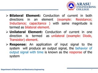
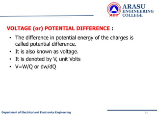
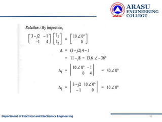
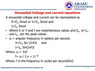
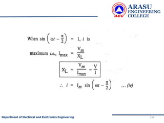
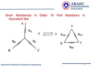
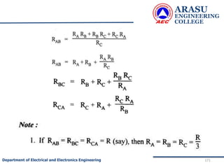
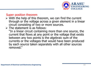
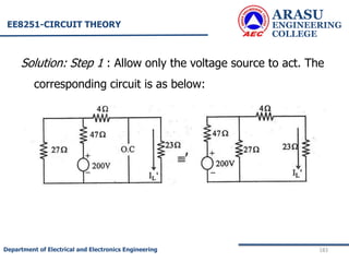
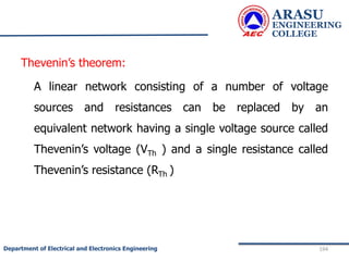
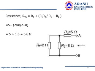
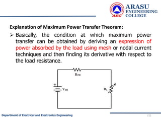
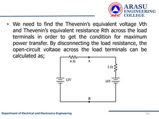
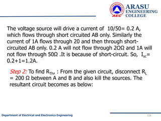
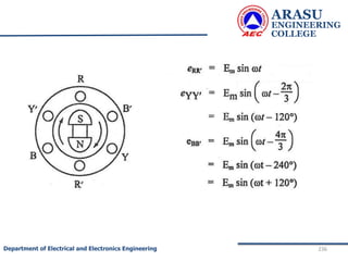
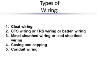
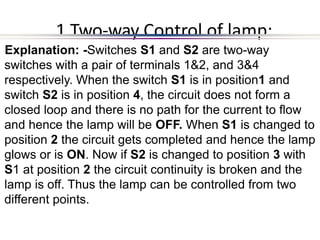
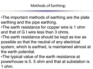
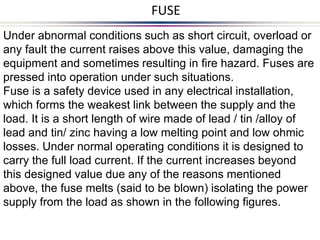
• To find RTh :
• The load resistance RL is removed. The cell is
disconnected and the wires are short as shown.
• The effective resistance across AB = Thevenin’s
resistance RTh .
• R1 is parallel to R2 and this combination in series with R3 ]](https://image.slidesharecdn.com/electriccircuitsandnetworktheorems-210506111409/85/Electric-circuits-and-network-theorems-197-320.jpg)


This document provides an introduction to electric circuits and network theorems. It discusses key concepts such as electrical networks, circuit elements, circuit analysis, Ohm's law, Kirchhoff's laws, series and parallel resistive circuits. The document is prepared by an assistant professor and contains illustrations and examples to explain concepts as well as practice problems and their solutions related to resistive circuits and applications of Ohm's law.


