Download to read offline
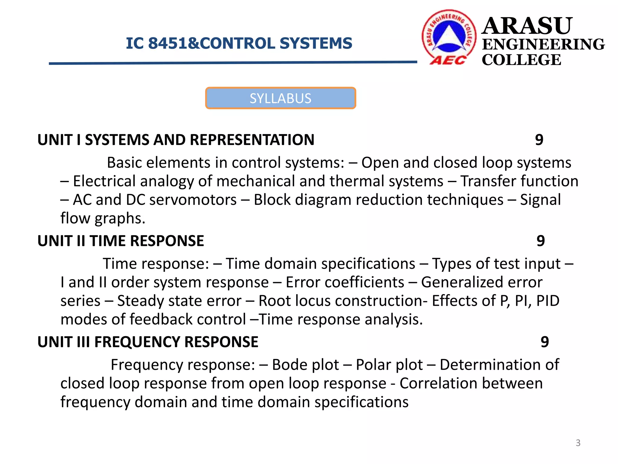
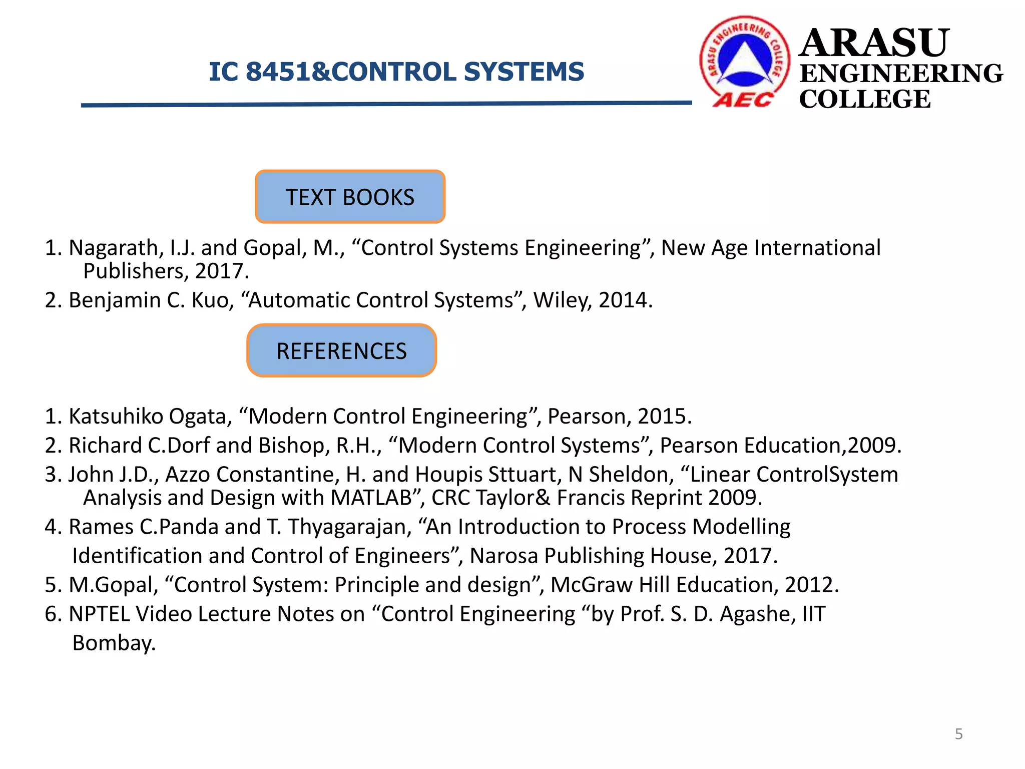

This document outlines the syllabus for the course "IC 8451&Control Systems". It contains 5 units: 1. Systems and Representation, which covers open and closed loop systems, transfer functions, and block diagram reduction techniques. 2. Time Response, covering time domain specifications, types of test inputs, and time response analysis. 3. Frequency Response, covering Bode plots, polar plots, and correlation between frequency and time domain specifications. 4. Stability and Compensator Design, including stability criteria, performance criteria, and compensator design using Bode plots. 5. State Variable Analysis, introducing concepts of state variables, state models, and controllability and observ