MCS 012 computer organisation and assembly language programming assignment…
•
26 likes•31,791 views

The document discusses binary arithmetic operations using 2's complement notation, conversion between number systems, UTF-8 encoding, designing logic circuits to count binary inputs, floating point number representation, RAM addressing, and input/output techniques. Examples of interrupt-driven and polling I/O are provided to explain how data can be read from keyboards and files.

Recommended
Recommended
More Related Content
What's hot
What's hot (20)
Viewers also liked
Viewers also liked (20)
Similar to MCS 012 computer organisation and assembly language programming assignment…
Similar to MCS 012 computer organisation and assembly language programming assignment… (20)
More from Dr. Loganathan R
More from Dr. Loganathan R (20)
Recently uploaded
Recently uploaded (20)
MCS 012 computer organisation and assembly language programming assignment…
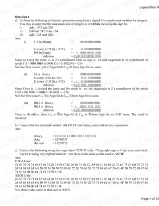
- 1. ot tC ot tC ot No N No N No Do Do Loganathan R D o D o Do py opy py opy py Question 1 a) Perform the following arithmetic operations using binary signed 2’s complement notation for integers. Co t C Co t C Co You may assume that the maximum size of integers is of 12 bits including the sign bit. ot ot ot i) Add – 512 and 298 No N No N No ii) Subtract 512 from – 64 Do Do iii) Add 1025 and 1023 D o Ans: i) D o 512 in Binary Do = 0010 0000 0000 py opy py opy py 2s comp of 512(i.e -512) = 1110 0000 0000 Co t C Co t C Co 298 in Binary = + 0001 0010 1010 ot ot ot Addition = Cy 1111 0010 1010 No N No N No Since no Carry the result is in 2’s compliment form so sign is –ve and magnitude is 2s compliment of Do Do result 1111 0010 1010 is 0000 1101 0110(214) = -214 D o o Do No Overflow since Cin to Sign bit & Cout from Sign bit are same. D py opy py opy py ii) 64 in Binary = 0000 0100 0000 2s comp of 64 (ie -64) = 1111 1100 0000 Co t C Co t C Co 2s comp of 512(i.e -512) = + 1110 0000 0000 ot ot ot Addition = Cy 1101 1100 0000 No No No Since Carry is 1, discard the carry and the result is –ve, the magnitude is 2’s compliment of the result N N Do Do 1101 1100 0000 = 0010 0100 0000 = -576 o o Do No Overflow since Cin to Sign bit & Cout from Sign bit is same. D iii) D1025 in Binary = 0100 0000 0001 py opy py opy py 1023 in Binary = + 0011 1111 1111 Co t C Co t C Co Addition = Cy 1000 0000 0000 ot ot ot There is Overflow, since Cin is to Sign bit & Cout is from Sign bit are NOT same. The result is No N No N No incorrect o Do o Do Do b) Convert the hexadecimal number: AB CD EF into binary, octal and decimal equivalent. D Ans: D py opy py opy py Binary = 1010 1011 1100 1101 1110 1111 Co t C Co t C Co Octal = 52746757 ot ot ot Decimal = 11259375 No N No N No c) Convert the following string into equivalent “UTF 8” code –“Copyright sign is © and you must check o Do o Do Do it prior to using copyrighted material”. Are these codes same as that used in ASCII? D Ans: UTF-8 Code: D py opy py opy py 43 6F 70 79 72 69 67 68 74 20 73 69 67 6E 20 69 73 20 C2 A9 20 61 6E 64 20 79 6F 75 20 6D 75 73 74 Co t C Co t C Co 20 63 68 65 63 6B 20 69 74 20 70 72 69 6F 72 20 74 6F 20 75 73 69 6E 67 20 63 6F 70 79 72 69 67 68 ot ot ot 74 65 64 20 6D 61 74 65 72 69 61 6C No No No ASCII Code: N N 43 6F 70 79 72 69 67 68 74 20 73 69 67 6E 20 69 73 20 C2 A9 20 61 6E 64 20 79 6F 75 20 6D 75 73 74 o Do o Do Do 20 63 68 65 63 6B 20 69 74 20 70 72 69 6F 72 20 74 6F 20 75 73 69 6E 67 20 63 6F 70 79 72 69 67 68 D D 74 65 64 20 6D 61 74 65 72 69 61 6C Yes, these codes same as that used in ASCII py opy py opy py Co Co Co Page 1 of 12
- 2. ot tC ot tC ot No N No N No Do Do Loganathan R D o D o Do py opy py opy py d) Design a logic circuit that takes a four digit binary input, counts the number of 1s in it, and produces it as the output. For example, if the input is 1101, then output will be 11 (as there are three ones in the Co t C Co t C Co input). Draw the truth table and use K-map to design the Boolean expressions for each of the output ot ot ot bits. Draw the resulting circuit diagram using AND – OR – NOT gates. No N No N No Ans: Do Do Truth Table D o D o Do A B Input C D X Output Y Z py opy py opy py 0 0 0 0 0 0 0 Co t C Co t C Co 0 0 0 1 0 0 1 0 0 1 0 0 0 1 ot ot ot 0 0 1 1 0 1 0 No N No N No 0 1 0 0 0 0 1 Do Do 0 1 0 1 0 1 0 D o D o Do 0 0 1 1 1 1 0 1 0 0 1 1 0 1 py opy py opy py 1 0 0 0 0 0 1 Co t C Co t C Co 1 0 0 1 0 1 0 1 0 1 0 0 1 0 ot ot ot 1 0 1 1 0 1 1 No N No N No 1 1 0 0 0 1 0 o Do o Do Do 1 1 0 1 0 1 1 D D 1 1 1 0 0 1 1 1 1 1 1 1 0 0 py opy py opy py K-Map Co t C Co t C Co Output bit X ot ot ot CD AB 00 01 11 10 No N No N No 00 o Do o Do Do 01 X = ABCD D D11 1 py opy py opy py 10 Co t C Co t C Co Output bit Y CD ot ot ot AB 00 01 11 10 No N No N No 00 1 o Do o Do Do 01 1 1 1 Y = A’CD+A’ BD+A’BC+ABC’+ACD’+AB’D D D11 1 1 1 py opy py opy py 10 1 1 1 Co t C Co t C Co Output bit Z CD ot ot ot AB 00 01 11 10 No N No N No 00 1 1 o Do o Do Do 01 1 1 D D 11 1 1 10 1 1 py opy py opy py Co Co Co Page 2 of 12
- 3. ot tC ot tC ot No N No N No Do Do Loganathan R D o D o Do py opy py opy py Z = A’B’C’D+A’B’CD’+A’BC’D’+ABC’D+ABCD’+AB’C’D’+AB’CD Co t C Co t C Co Circuit Diagram using AND – OR – NOT gates: ot ot ot (Draw yourself for those 3 expressions) No N No N No Do Do e) Design a two bit counter (a sequential circuit) that counts as 0, 2, 0, 2... and so on. You should show D o o Do the state table, state diagram, the kmap for circuit design, logic diagram of the resultant design using D D flip-flop. py opy py opy py Ans: Co t C Co t C Co f) Design a floating point representation of 16 bits closer to IEEE 754 format. The number should have a ot ot ot biased exponent of 5 bits. You may assume that the mantissa is in normalized form; the exponent bias No N No N No of 15; and one bit is used for the sign bit in the mantissa. Represent the number (24.125)10 using this Do Do format D o Ans: D o Binary of 24.125 Do= 11000.001 = 1.1000001X24 py opy py opy py Normalized Form Sign bit =0 Co t C Co t C Co Exponent =4 ot ot ot Biased Exponent = 15+4 No No No = 19 N N Do Do = 10011 o o Do Significand = 1000001 D D py opy py opy py 15 14 10 9 0 Co t C Co t C Co 0 1 0 0 1 1 1 0 0 0 0 0 1 0 0 0 ot ot ot S Exponent Significand No N No N No o Do o Do Do Question 2 D D a) A RAM has a capacity of 32 K × 16. (2 Marks) i) How many data input and data output lines does this RAM need to have? py opy py opy py ii) How many address lines will be needed for this RAM? Co t C Co t C Co Ans: ot ot ot i) Data Input Lines = 16 No No No Data Output Lines = 16 ii) N N Number of Address Lines Required = 15 D o Do D o Do Do b) Consider a RAM of 512 words with a word size of 32 bits. Assume that this memory have a cache memory of 8 Blocks with block size of 64 bits. For the given memory and Cache in the statements as py opy py opy py above, draw a diagram to show the address mapping of RAM and Cache, if two way set associative Co t C Co t C Co memory to cache mapping scheme is used. ot ot ot Ans: RAM Size = 512 X 32 No N No N ⇒1 Block of CacheNo Cache Memory Size = 8 Blocks o Do o Do Do Cache Memory Block size = 64 words D D = 2 Words of RAM Index size = 3 bits py opy py opy py Tag = 6 bits Co Co Co Page 3 of 12
- 4. ot tC ot tC ot No N No N No Do Do Loganathan R D o D o Do py opy py opy py Mapping: Co t C Co t C Co Index Tag Data Tag Data 000 000000 111111 ot ot ot 001 001000 000101 No N No N No D o Do D o Do Do 110 110110 111010 py opy py opy py 111 100111 010011 Co t C Co t C Co c) Explain which of the Input/output techniques that will be used for the following operations. Also explain the I/O techniques. ot ot ot i) Reading data from a keyboard No N No N No ii) Reading data from a file. Do Do Ans: D o D o Do i) For Reading data from a keyboard the interrupt driven I/O technique will be suitable. With interrupt driven I/O, when the interface determines that the device is ready for data transfer, it py opy py opy py generates an interrupt request to the computer. Upon detecting the external interrupt signal, the Co t C Co t C Co processor stops the task it is processing, branches to a service program to process the I/O transfer, and then returns to the task it was originally performing which results in the waiting ot ot ot time by the processor being reduced. No N No N No Do Do Interrupt driven input/output Technique: D o D o Do py opy py opy py Co t C Co t C Co ot ot ot No N No N No D o Do D o Do Do py opy py opy py Co t C Co t C Co ot ot ot No N No N No D o Do D o Do Do py opy py opy py Co t C Co t C Co ot ot ot No N No N No D o Do D o Do Do py opy py opy py Co Co Co Page 4 of 12
- 5. ot tC ot tC ot No N No N No Do Do Loganathan R D o D o Do py opy py opy py ii) For Reading data from a file the direct memory access (DMA) technique is suitable since it requires large amount of data transfer from hard disk. In this mode, the I/O interface and main Co t C Co t C Co memory exchange data directly, without the involvement of processor. The DMA interface ot ot ot transfers the entire block of data, one word at a time, directly to or from memory, without No N No N No going through the processor. When the transfer is complete, the DMA interface sends an Do Do interrupt signal to the processor. Thus, in DMA the processor involvement can be restricted at D o o Do the beginning and end of the transfer D py opy py opy py Direct Memory Access (DMA) Technique Co t C Co t C Co A technique called cycle stealing allows the DMA interface to transfer one data word at a time, ot ot ot after which it must return control of the bus to the processor. The processor merely delays its No N No N No operation for one memory cycle to allow the directly memory I/O transfer to “steal” one Do Do memory cycle. When an I/O is requested, the processor issues a command to the DMA D o D o Do interface by sending to the DMA interface the following information: Which operations (read or write) to be performed, using the read or write control lines. The address of I/O devices, which is to be used, communicated on the data lines. py opy py opy py The starting location on the memory where the information will be read or written to be Co t C Co t C Co communicated on the data lines and is stored by the DMA interface in its address ot ot ot register. No No No The number of words to be read or written is communicated on the data lines and is N N Do Do stored in the data count register. D o D o Do py opy py opy py Co t C Co t C Co ot ot ot No N No N No D o Do D o Do Do py opy py opy py Co t C Co t C Co ot ot ot d) Find the average disk access time that reads or writes a 1024 byte sector. Assume that the disk rotates No N No N No at 18000 rpm; each track of the disk has 128 sectors and data transfer rate of the disk is 100 Do Do MB/second. (Please calculate data transfer time, assume a suitable seek time and calculate the average D o D o latency time) Ans: Do py opy py opy py Assume seek time = 12 ms Co t C Co t C Co Average Rotational Latency = (0.5 * 60)/ 18000 = 1.7ms ot ot ot Transfer time = 1KB/100MB/s No N No N No =.01/1024s Do Do = 0.01ms D o D o Average Disk Access Time Do = Seek time + Rotational Latency + Transfer time = 12 ms + 1.7ms + 0.01ms py opy py opy py = 13.71ms Co Co Co Page 5 of 12
- 6. ot tC ot tC ot No N No N No Do Do Loganathan R D o D o Do py opy py opy py e) What is the purpose of FAT in Windows? What construct do you use in Linux/Unix instead of FAT? Explain the differences between the two. Co t C Co t C Co Ans: ot ot ot The FAT maps the usage of data space of the disk. It contains information about the space used by No N No N No each individual file, the unused disk space and the space that is unusable due to defects in the disk. Do Do One of the fundamental differences in files system semantics between Linux / Unix and Windows is D o D o the idea of inodes. Do Windows FAT entry can contain any of the following: unused cluster py opy py opy reserved cluster py Co t C Co t C Co bad cluster ot ot ot last cluster in file No N No N No next cluster number in the file. Do Do In Windows it is named FAT32, The cluster entry uses 32-bit numbers. The minimum size for a D o D o Do FAT32 volume is 512MB. It has reserved the top four bits of every cluster number in a FAT32 file. py opy py opy py In the UNIX system, the information related to all these fields is stored in an Inode table on the disk. Co t C Co t C Co For each file, there is an inode entry in the table. Each entry is made up of 64 bytes and contains the relevant details for that file. These details are: ot ot ot Owner of the file No N No N No Group to which the Owner belongs Do Do File type D o D o Do File access permissions Date & time of last access py opy py opy py Date & time of last modification Co t C Co t C Co Size of the file No. of links ot ot ot Addresses of blocks where the file is physically present. No N No N No f) Define each of the following term. Explain the main purpose / use / advantage. o Do o Do Do i) ZBR in the context of disks D D ii) SCSI iii) Colour Depth py opy py opy py iv) Graphics Accelerators Co t C Co t C Co v) Monitor Resolution ot ot ot vi) Active matrix display Ans: No N No N No i) ZBR Zone Bit Recording (ZBR) is used by disk drives to store more sectors per track on outer o Do o Do Do tracks than on inner tracks D D Using ZBR the drive divides all the tracks into a number of zones, and the inner track of each zone is packed as densely as it can, with the other tracks in that same zone recorded with the same py opy py opy py read/write rate. This permits the drive to have more bits stored in each track outside of the Co t C Co t C Co innermost zone than drives not using this technique. Storing more bits per track equates to achieving a higher total data capacity on the same disk area ot ot ot ii) SCSI - Small Computer System Interface is a set of standards for physically connecting and No N No N No transferring data between computers and peripheral devices. A SCSI controller connects directly o Do o Do Do to the computer bus on one side and controls another bus (called SCSI bus) on the other side. D D Since the SCSI controller is connected to the computer’s bus on one side and to the SCSI bus on the other side, it can communicated with the processor and memory and can also control the py opy py opy py devices connected to the SCSI bus Co Co Co Page 6 of 12
- 7. ot tC ot tC ot No N No N No Do Do Loganathan R D o D o Do py opy py opy py SCSI is most commonly used for hard disks and tape drives, but it can connect a wide range of other devices, including scanners and CD drives, although not all controllers can handle all Co t C Co t C Co devices ot ot ot Advantage of these drives is that a single SCSI controller can communicate simultaneously with No N No N No up to seven 16-bit SCSI devices or up to 15 Wide or Ultra-Wide devices. Do Do iii) Colour Depth is the number of bits assigned to each pixel to code colour information in it. These D o o Do are also called Colour Planes because each bit of a pixel represents a specific colour and the bit at D the same position on every pixel represents the same colour. py opy py opy py Practically, the number of colours are an exponential power of 2, since for Colour Depth n, colours can be displayed Co t C Co t C Co Improved quality video ot ot ot iv) Graphics Accelerator is a chip in video card. The Graphic Accelerator is actually the modern No N No N No development of a much older technology called the Graphic Co-Processor. The accelerator chip Do Do has built-in video functions to execute the algorithms for image construction and rendering. D o o Do It determines whether your system can show 3-D graphics, how quickly your system displays a D drop-down menu, how good is your video playback, etc. py opy py opy py It determines the amount and kind of memory in the frame buffer and also the resolution your PC can display. Co t C Co t C Co v) Monitor Resolution is the number of distinct pixels in each dimension that can be displayed in the ot ot ot monitor. No No No Horizontal Frequency: The time to scan one line connecting the right edge to the left edge of the N N Do Do screen horizontally is called the Horizontal cycle and the inverse number of the Horizontal cycle is o o Do called Horizontal Frequency. D D Vertical Frequency: The screen has to repeat the same image many times per second to display an image to the user. The frequency of this repetition is called Vertical Frequency or Refresh Rate. py opy py opy py If the resolution generated by the video card and the monitor resolution is properly matched, we Co t C Co t C Co get a good quality display. However, the actual resolution achieved is a physical quality of the ot ot ot monitor No No No vi) Active matrix display is called TFT (Thin Film Transistor) technology. In this there is a transistor N N at every pixel acting as a relay, receiving a small amount and making it much higher to activate o Do o Do Do the pixel. Since the amount is smaller, it can travel faster and hence response times are much D D faster. However, TFTs are much more difficult to fabricate and are costlier. for image construction and rendering py opy py opy py Co t C Co t C Co Question 3 ot ot ot a) Assume that a new machine has been developed which has only 16 general purpose registers, but have No No No a big high speed RAM. The machine uses stack for procedure calls. The machine is expected to N N handle all the object oriented languages. List four addressing modes that must be supported by such a o Do o Do Do machine. Give justification of the selection of each of the addressing modes. D D Ans: Addressing Mode Justification py opy py opy py Direct Used for global variables and less often for local variables Co t C Co t C Co Index To access members of an array and iterative local variables ot ot ot Register Frequently used for storing local variables of procedures No No No Stack Used for local variables, parameter passing N N o Do o Do Do b) Assume a hypothetical machine that has only PC, AC, MAR, IR, DR and Flag registers. (You may D D assume the roles of these registers same as that are defined in general for a von Neumann machine) py opy py opy py Co Co Co Page 7 of 12
- 8. ot tC ot tC ot No N No N No Do Do Loganathan R D o D o Do py opy py opy py The instructions of this machine can take two operands - one the operand of these must be a register operand. It has an instruction: Co t C Co t C Co SUB AC, X; // it performs the operation AC AC – Content of location X. ot ot ot Write and explain the sequence of micro-operations that are required to fetch and execute the No N No N No instruction. Make and state suitable assumptions, if any. Do Do Ans: D o o Do Instruction execution using the micro-operations requires: D Instruction fetch: fetching the instruction from the memory. py opy py opy py Instruction decode: decode the instruction. Operand address calculation: find out the effective address of the operands. Co t C Co t C Co Execution: execute the instruction. ot ot ot Interrupt Acknowledge: perform an interrupt acknowledge cycle if an interrupt request is No N No N No pending. Do Do Instruction fetch: D o D o Do Transfer the address of PC to MAR. (Register Transfer) MAR puts its contents on the address bus & issues a memory read signal. DR ← (MAR) MAR← PC py opy py opy py The word so read is placed on the data bus and it is accepted by the Data PC←PC+1 Co t C Co t C Co register. The PC is incremented by one. The instruction is transferred from data register to the Instruction register. IR←DR ot ot ot Instruction decode: No N No N No The Control Unit determines the operation that is to be performed and the addressing mode of the o Do o Do Do Operand D D Operand address calculation(For Indirect Addressing): Transfer the address bits of instruction to the MAR. MAR←DR(Address) py opy py opy py Perform a memory read operation as done in fetch cycle and the desired DR ←(MAR) Co t C Co t C Co address of the operand is obtained in the DR Transfer the address part so obtained in DR as the address part of IR(Addr)←DR(Addr) ot ot ot instruction No N No N No Execution: Do Do Transfer the address portion of the instruction to the MAR MAR← IR (Addrs) D o D o Do Read the memory location A and bring the operand in the DR Subtract the DR from AC using ALU and bring the results back to AC. DR←(MAR) AC←AC - DR py opy py opy py Interrupt Acknowledge: Co t C Co t C Co Then check whether there is any pending interrupt request for the interrupts that are enabled. If interrupt has occurred then that Interrupt may be processed. ot ot ot Transfer the contents of PC to DR DR←PC No N No N No Place the address of location, where the return address MAR← Address of location for o Do o Do Do is to be saved, into MAR saving return address D D Store the contents of PC in the memory using DR and (MAR)←DR MAR. Transfer the address of the first instruction of PC← address of the first instruction py opy py opy py interrupt servicing routine to the PC interrupt service programs Co t C Co t C Co c) Assume that you have a machine as shown in section 3.2.2 of Block 3 having the micro-operations as given in Figure 10 on page 62 of Block 3. Consider that R1 and R2 both are 8 bit registers and ot ot ot contains 11110101 and 10101001 respectively. What will be the values of select inputs, carry-in input No N No N No and result of operation if the following micro-operations are performed? (For each micro operation o Do o Do Do you may assume the initial value of R1 and R2 as defined above) D D 1. Decrement R1 2. R1 Exclusive OR R2 py opy py opy py 3. Subtract R1 from R2 with borrow Co Co Co Page 8 of 12
- 9. ot tC ot tC ot No N No N No Do Do Loganathan R D o D o Do py opy py opy py 4. Shift Right R2 Ans: Co t C Co t C Co S3 S2 S1 S0 Ci F Micro Operation Result ot ot ot 0 0 1 1 0 F=x–1 R ← R1 – 1 11110100 No N No N No 0 1 1 0 - F = x y R ← R1 R2 01011100 Do Do 0 0 1 0 0 F = x + y’ R ← R1 + R’2 01001100 D o D o1 1 Do - - - F = Shr(y) R ← Shr(R1) 01010100 d) Explain the functions performed by the Micro-programmed Control Unit with the help of diagram py opy py opy py Control Units? Also explain the role of sequencing logic component of Control Unit. Co t C Co t C Co Ans: Diagram: ot ot ot Draw Figure 5: Operation of Micro-Programmed Control Unit in Page 74 of Sec 4.5 in Block 3 No N No N No Functions performed by the Micro-programmed Control Unit: Do Do 1. The sequence logic unit specifies the address of the control memory word that is to be read, in D o D o Do the Address Register of the Control Memory. It also issues the READ signal. 2. The desired control memory word is read into control memory Buffer Register. py opy py opy py 3. The content of the control memory buffer register is decoded to create control signals and Co t C Co t C Co next-address information for the sequencing logic unit. 4. The sequencing logic unit finds the address of the next control word on the basis of the next- ot ot ot address information from the decoder and the ALU flags. No N No N No Role of sequencing logic component Do Do Loading the control memory address register D o o Do Issues a read command to control memory D e) What are the advantages of instruction pipeline? Explain with the help of a diagram for a 3 stage py opy py opy py instruction pipeline having cycles IFD (Instruction Fetch and Decode), OF (Operand Fetch) and ES Co t C Co t C Co (Execute and store results). What can be the problems of such an instruction pipeline? Ans: ot ot ot It improves the performance of the CPU Considerably. The instruction pipelining involves No N No N No decomposing of an instruction execution to a number of pipeline stages. A pipeline allows overlapped Do Do execution of instructions. During the course of execution of an instruction the following may be a D o D o Do scenario of execution in 3 stage instruction pipeline having cycles IFD, OF and ES. py opy py opy py Time Slot → 1 2 3 4 5 6 7 Co t C Co t C Co Instruction 1 IFD OF ES Instruction 2 IFD OF ES ot ot ot Instruction 3 IFD OF ES No N No N No Instruction 4 IFD OF ES Do Do Instruction 5 IFD OF ES D o D o Do The pipeline stages are like steps each to be completed in a time slot. The first instruction execution is completed on completion of 3rd time slot, but afterwards, in each time slot the next instruction gets py opy py opy py executed. So, in ideal conditions one instruction is executed in the pipeline in each time slot. After the 3rd time slot and afterwards the pipe is full. In the 3rd time slot the stages of execution of three Co t C Co t C Co instructions are: ot ot ot IFD (Instruction Fetch and Decode) No N No N No OF (Operand Fetch) Do Do ES (Execute and store results) D o D o Do f) Assume that a RISC machine has 64 registers out of which 16 registers are reserved for the Global py opy py opy py variables. Assuming that 8 of the registers are to be used for one function, explain how the remaining Co Co Co Page 9 of 12
- 10. ot tC ot tC ot No N No N No Do Do Loganathan R D o D o Do py opy py opy py registers will be used as overlapped register windows. How will these registers be used for parameter passing for subroutine calls? Explain with the help of diagram. Co t C Co t C Co Ans: ot ot ot Register# Used For No N No N No Global Variable les 0-15 Do Do Required by Function A Function B Function C o o Do (16 Registers) D D Function A Used by parameters Temporary 16-21 py opy py opy py of fC that may be variables of (6 Registers) passed to next call function C Co t C Co t C Co 22-29 Used for local Local variables ot ot ot (8 Registers) variable of fC of function C No N No N No Used by parameters Temporary 30-35 Parameters of Do Do that were passed variables of o o Do (6 Registers) function C D D from fB to fC function B 36-43 Local Variables Local variable of fB py opy py opy py (8 Registers) of function B Co t C Co t C Co 44-49 Parameters that were Temporary variables Parameters of (6 Registers) passed from fA to fB of function A function B ot ot ot 50-57 Local Variables of No No No Local variable of fA N N (8 Registers) function A Do Do 58-63 Parameter passed to Parameters of D o Question 4 D o (6 Registers) fA Do function A py opy py opy py a) Write a program in 8086 assembly Language (with proper comments) to find if a given sub-string is Co t C Co t C Co prefix of a given string. For example, the sub-string “Assembly” is the prefix in the string “Assembly Language Programming.” You may assume that the sub-string as well as the string is available in the ot ot ot memory. You may also assume that the end of the strings is the character „$‟. Make suitable No N No N No assumptions, if any. Do Do Ans: D o D o Do ;Program to check if a given sub-string is prefix of a given string .model small ;1 ds & 1 CS py opy py opy py .data ;Data Segment Co t C Co t C Co mstr db 'Assembly Language Programming' sstr db 'Assembly' ot ot ot slen dw slen-sstr No N No N No smsg db 'The given Sub string is a Prefix$' Do Do fmsg db 'The given Sub string is NOT Prefix$' D o .code start: D o Do py opy py opy py mov ax, @data mov ds, ax ;initialize DS with Data Segment Base Co t C Co t C Co mov es, ax ;initialize ES with Data Segment Base ot ot ot lea si, mstr ;Offset of main string to SI No N No N No lea di, sstr ;Offset of sub string to DI Do Do mov cx, slen ;String Length of Sub sring to CX D o D o repe cmpsb je ldmsg Do ;compare sub string with main string ;Mach found py opy py opy py lea dx, fmsg ;No match so store offset of Fail msg Co Co Co Page 10 of 12
- 11. ot tC ot tC ot No N No N No Do Do Loganathan R D o D o Do py opy py opy py jmp disp ldmsg: Co t C Co t C Co lea dx, smsg ;store offset of Success msg ot ot ot disp: No N No N No mov ah, 9 Do Do int 21h ;Display message D o D o mov ah, 4ch int 21h Do ;exit to operating system. py opy py opy py end start ;stop the assembler. Output: Co t C Co t C Co The given Sub string is a Prefix ot ot ot b) Write a program in 8086 assembly language to convert a two digit packed BCD number into No N No N No equivalent ASCII digits. Your program should print the two ASCII digits. You may assume that the Do Do BCD number is in the AL register. D o Ans: D o .model small Do py opy py opy py .data msg db 'The Given Packed BCD : ' Co t C Co t C Co bcd 8 dup() ;To display binary digits of BCD ot ot ot db 10,13,'Equivalent ASCII Digits: ' No No No asci db 30h,30h,'$' N .code segment N o Do o Do Do start: D D mov ax, @data mov ds, ax ;Initializing data Segment register py opy py opy py mov al, 01110101b ; binary number Co t C Co t C Co lea si, bcd ot ot ot mov cx,8 ;Pointer to each digit of BCD No No No agn: N rol al, 1 N ;Extract BCD digit by rotating digits to Carry o Do o Do Do jnc cntnu ;If No carry store ascii of 0 D D mov [si],'1' jmp nxt ;Store ascii of 1 py opy py opy py cntnu: Co t C Co t C Co mov [si],'0' ;Store ascii of 0 ot ot ot nxt: No No No inc si N loop agn N ;Till all 8 digits of BCD D o Do D o mov bl, al mov cl, 4 Do Do ;To Mask lower 4 bits of BCD py opy py opy py shr al, cl ;Shift higher 4 bits to lower Co t C Co t C Co add asci, al ;Store in memory to display ot ot ot and bl, 0fh ;Mask higher 4 bits of BCD add asci+1,bl ;Store in memory to display No N No N No o Do o Do Do lea dx, msg ;Display All D D mov ah, 9 int 21h py opy py opy py Co Co Co Page 11 of 12
- 12. ot tC ot tC ot No N No N No Do Do Loganathan R D o D o Do py opy py opy py mov ah, 4ch ; exit to operating system. int 21h Co t C Co t C Co end start ; stop the assembler. ot ot ot No N No N No Output: Do Do The Given Packed BCD : 01110101 D o o Do Equivalent ASCII Digits: 75 D c) Write a simple subroutine that receives one parameter value. The subroutine checks if the passed py opy py opy py parameter value is 0 or otherwise. In case, the value is 0 then it prints FALSE, otherwise it prints TRUE. Make suitable assumptions, if any. Co t C Co t C Co Ans: ot ot ot ;assume parameter is passed in register BL No N No N No .model small ;1 DS & 1 CS Do Do .data ;Data Segment D o t f D o db db 'TRUE$' Do 'FALSE$' py opy py opy py .code Co t C Co t C Co start: ot ot ot mov ax, @data No No No mov ds, ax ;initialize DS with Data Segment Base N mov bh,01 N ;Parameter to be passed to subroutine o Do o Do Do call checkp ;call subroutine D D mov ah, 4ch int 21h ;exit to operating system. py opy py opy py Co t C Co t C Co proc checkp ot ot ot cmp bh,0 ;check parameter is 0 or Not No No No je ldmsg ;If 0 load False message N lea dx, t N ;NOT 0 so, store offset of True message o Do o Do Do jmp disp D ldmsg:D py opy py opy py lea dx, f ;store offset of False msg Co t C Co t C Co ot ot ot disp: No No No mov ah, 9 N int 21h N ;Display message o Do o Do Do ret D D endp checkp ;end of procedure end start ;stop the assembler. py opy py opy py Co t C Co t C Co Output: ot ot ot TRUE No N No N No D o Do D o Do Do py opy py opy py Co Co Co Page 12 of 12