Downloaded 160 times


![FORMATS
INSTRUCTION
FACTORS IN USING
ADDRESSING BITS:
Register versus memory
A machine must have registers so that data can be brought
into the processor for processing. With a single user-visible
register (usually called the accumulator), one operand
address is implicit and consumes no instruction bits.
However, single-register programming is awkward and
requires many instructions. Even with multiple registers, only
a few bits are needed to specify the register. The more that
registers can be used for operand references, the fewer bits
are needed. A number of studies indicate that a total of 8
to 32 user-visible registers is desirable [LUND77, HUCK83].
Most contemporary architectures have at least 32 registers.](https://image.slidesharecdn.com/chapter11addressing-150130235842-conversion-gate01/75/Chapter11-addressing-59-2048.jpg)
![FORMATS
INSTRUCTION
PDP-11
designed to provide a powerful and flexible
instruction set within the constraints of a 16-bit
minicomputer [BELL70]
employs a set of eight 16-bit general-purpose
registers: one is used as a stack pointer for special-
purpose stack operations, and one is used as the
program counter, which contains the address of
the next instruction
Because of its capability being complex, it
increases both hardware cost and programming
complexity.](https://image.slidesharecdn.com/chapter11addressing-150130235842-conversion-gate01/75/Chapter11-addressing-64-2048.jpg)
![FORMATS
INSTRUCTION
VAX
was designed using these two criteria: [STRE78]
This decision affects, and is affected by, memory
size, memory organization, bus structure,
processor complexity, and processor speed.
also determines the richness and flexibility of the
machine as seen by the assembly-language
programmer
1. All instruction should have the “natural” no. of operands.
2. All instruction should have the same generality in specification.](https://image.slidesharecdn.com/chapter11addressing-150130235842-conversion-gate01/75/Chapter11-addressing-65-2048.jpg)

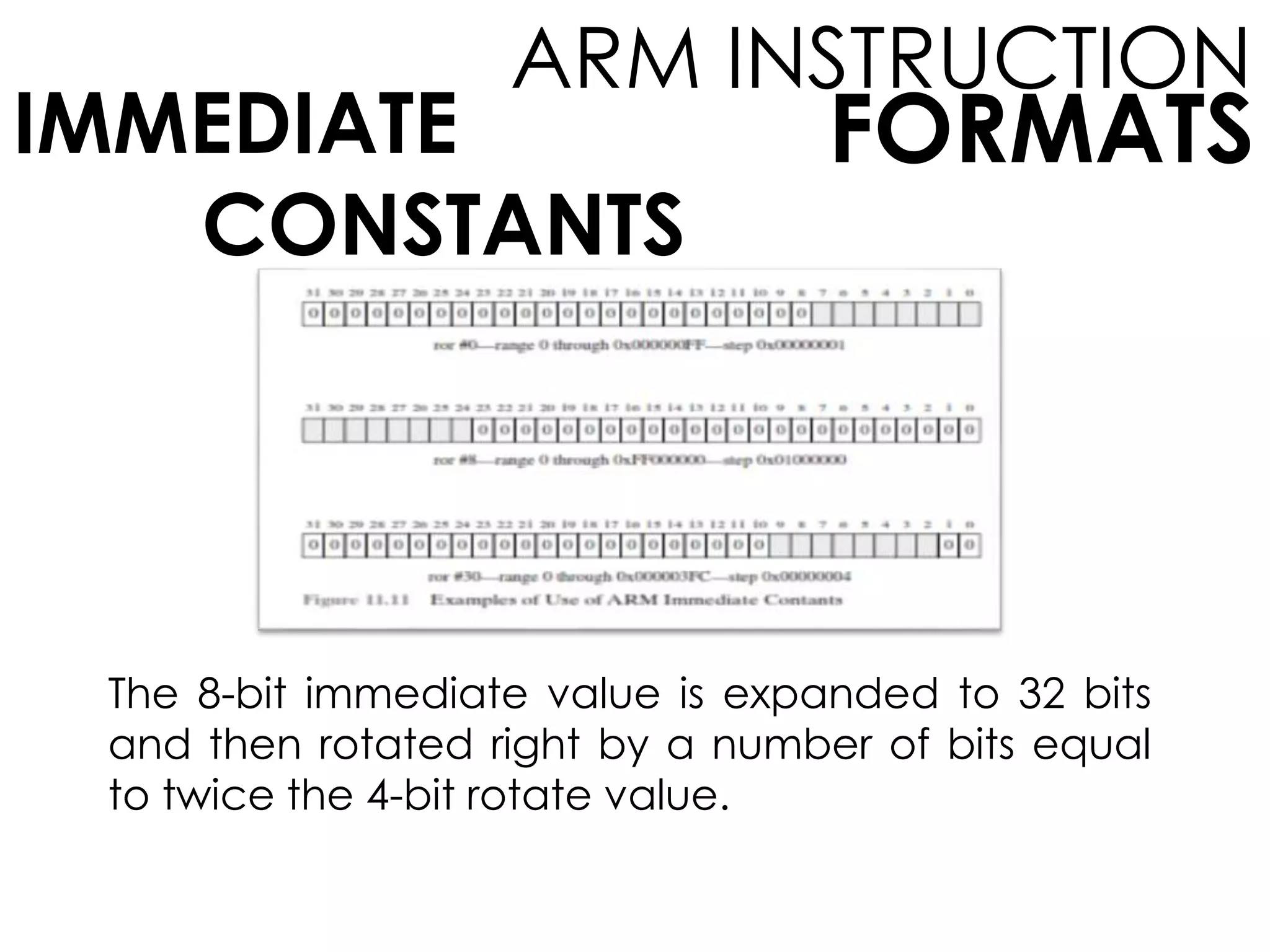


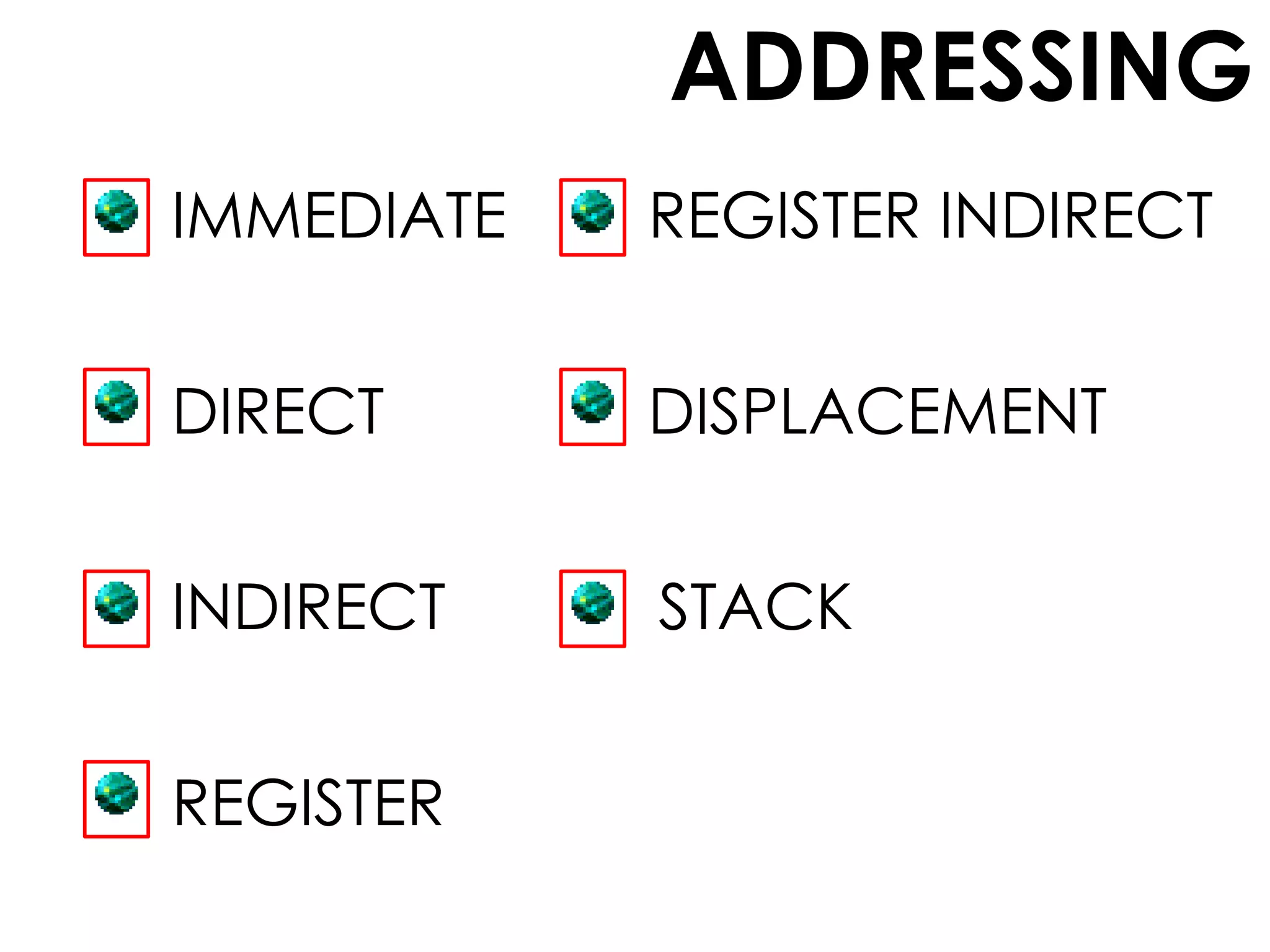
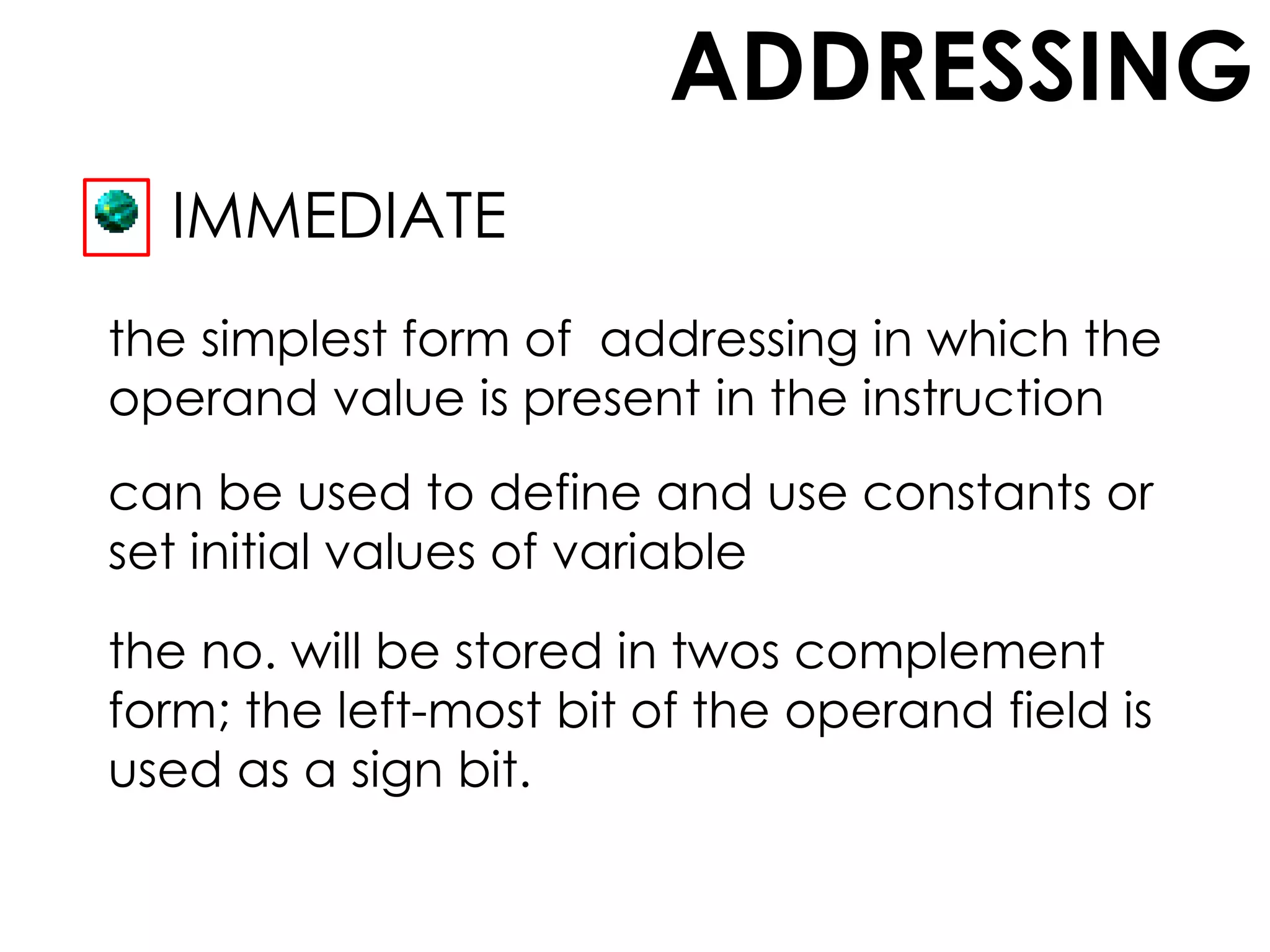
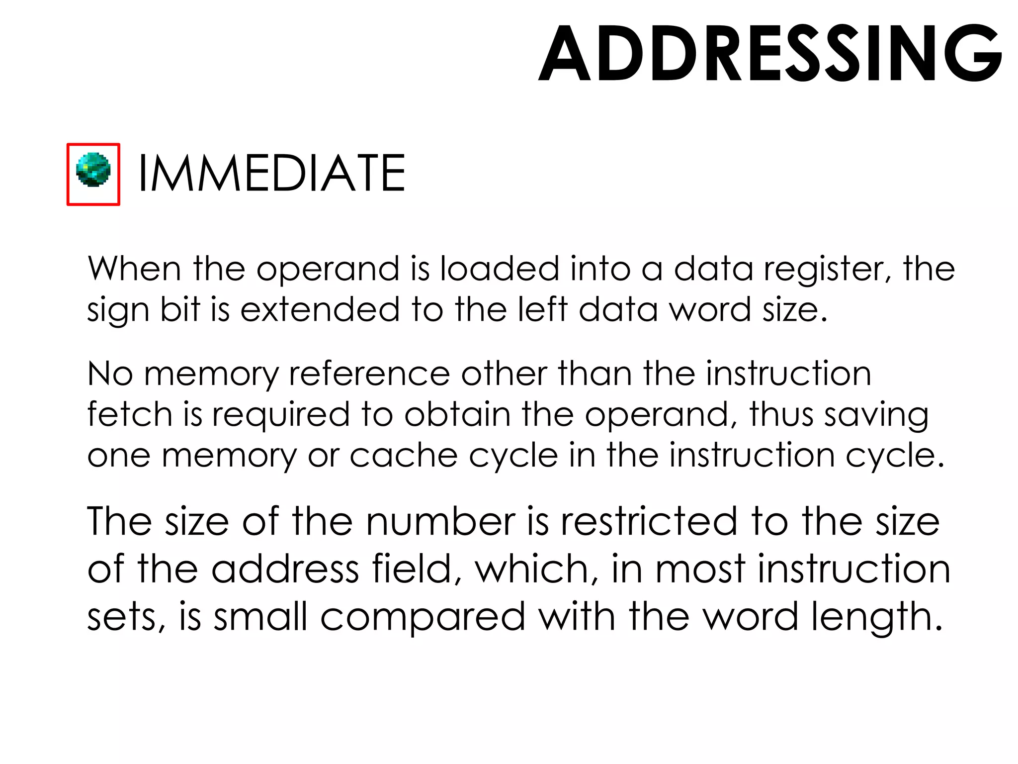
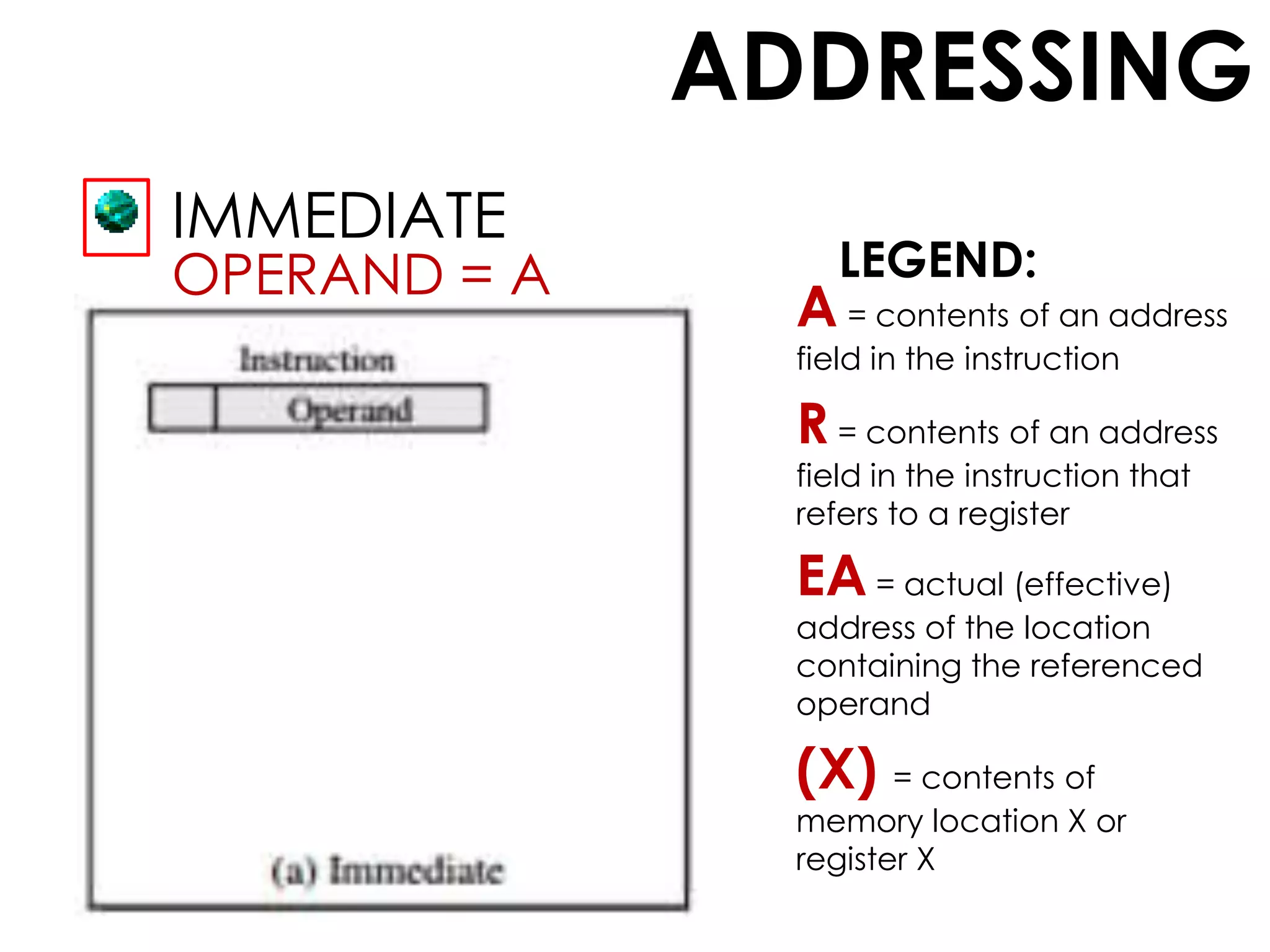
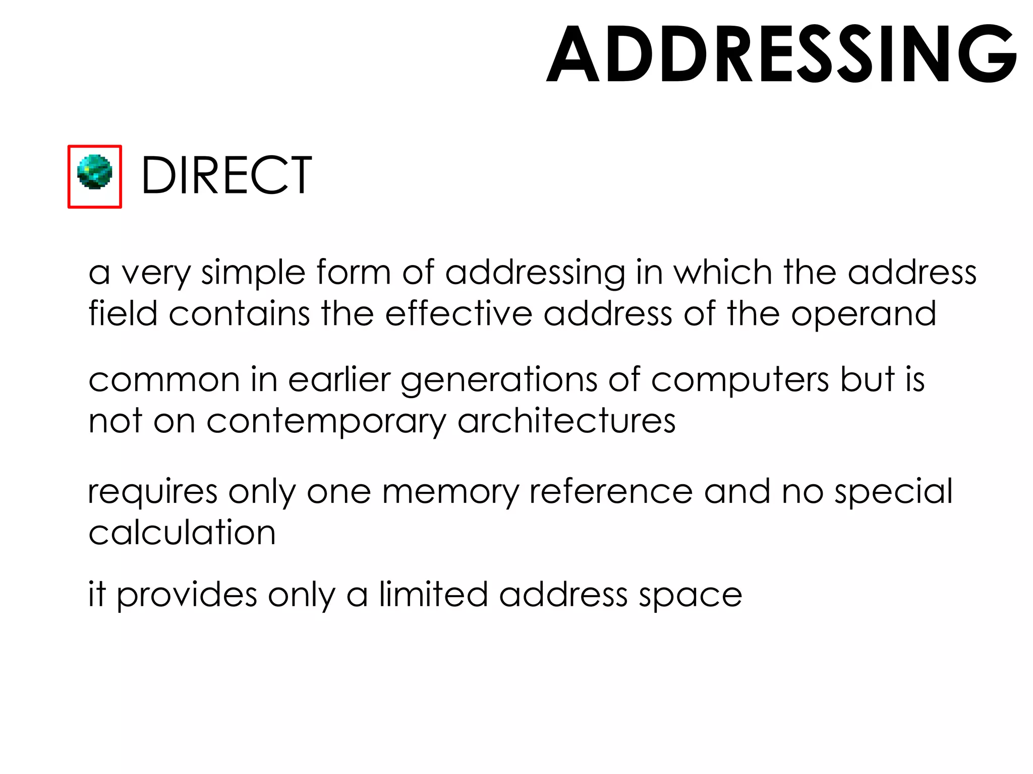
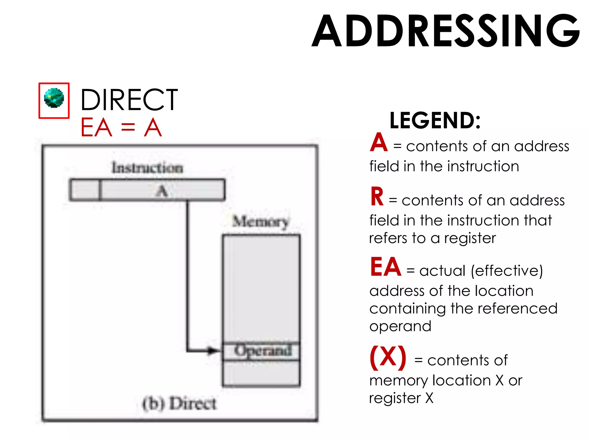
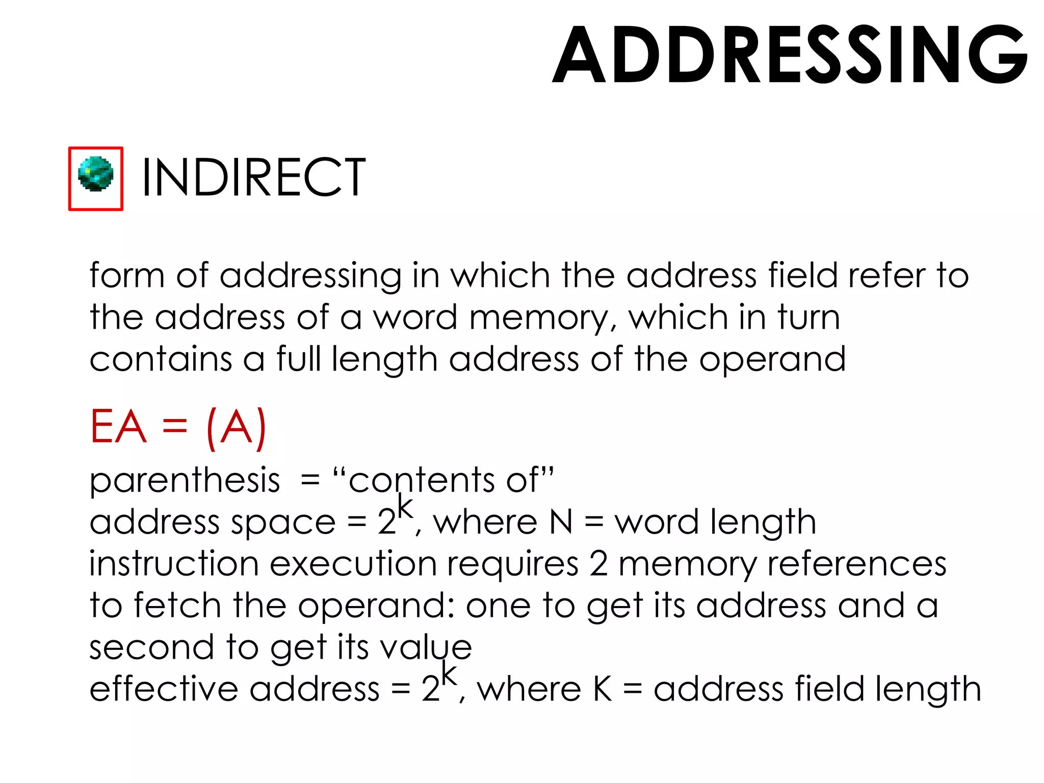
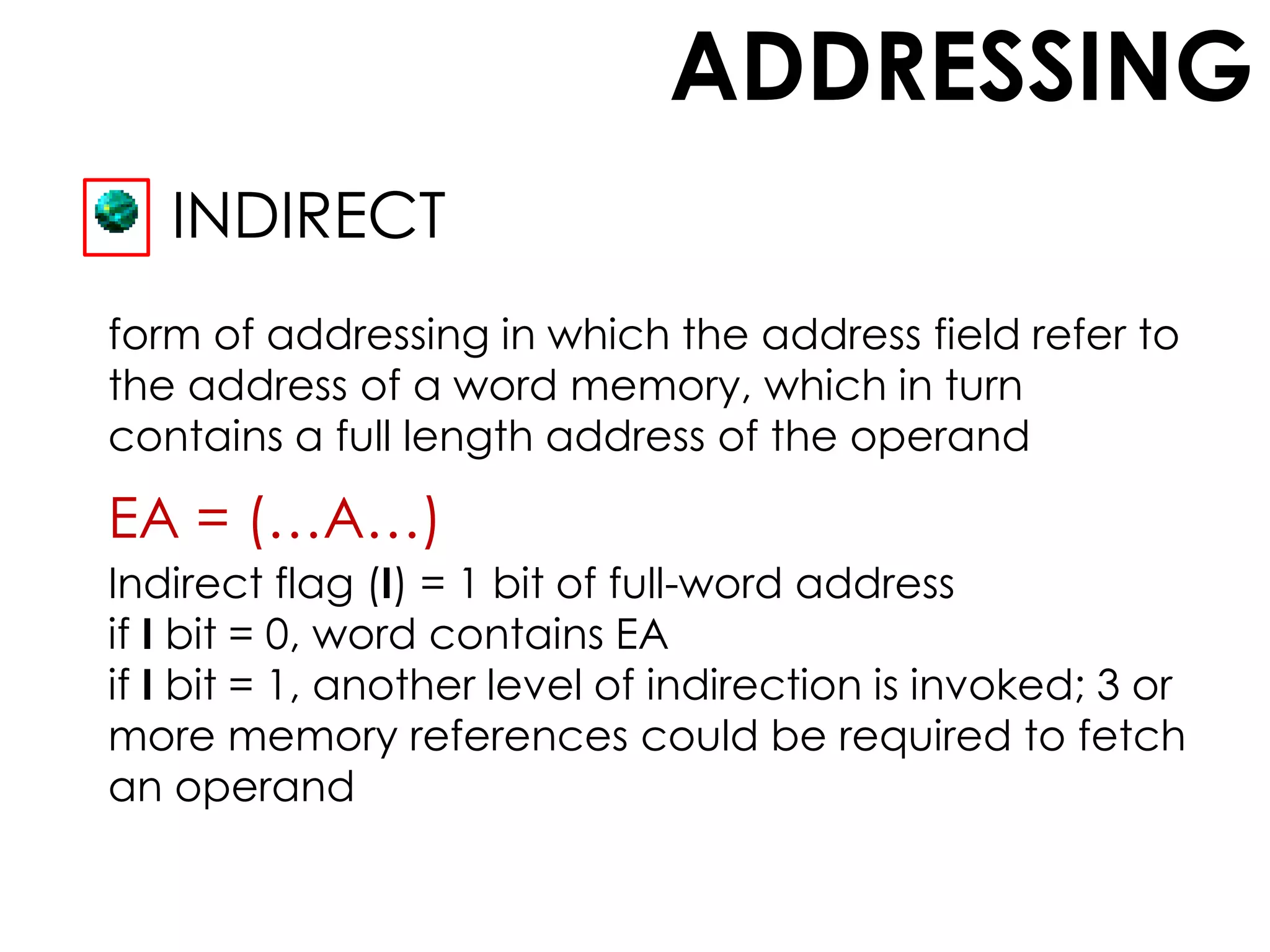
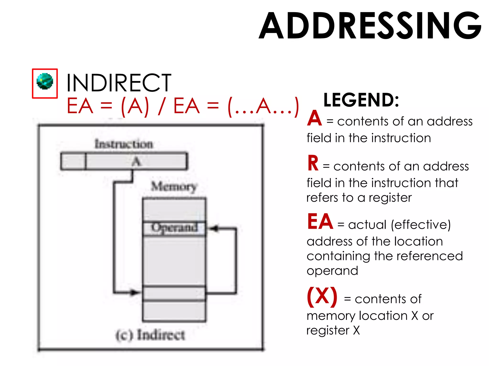
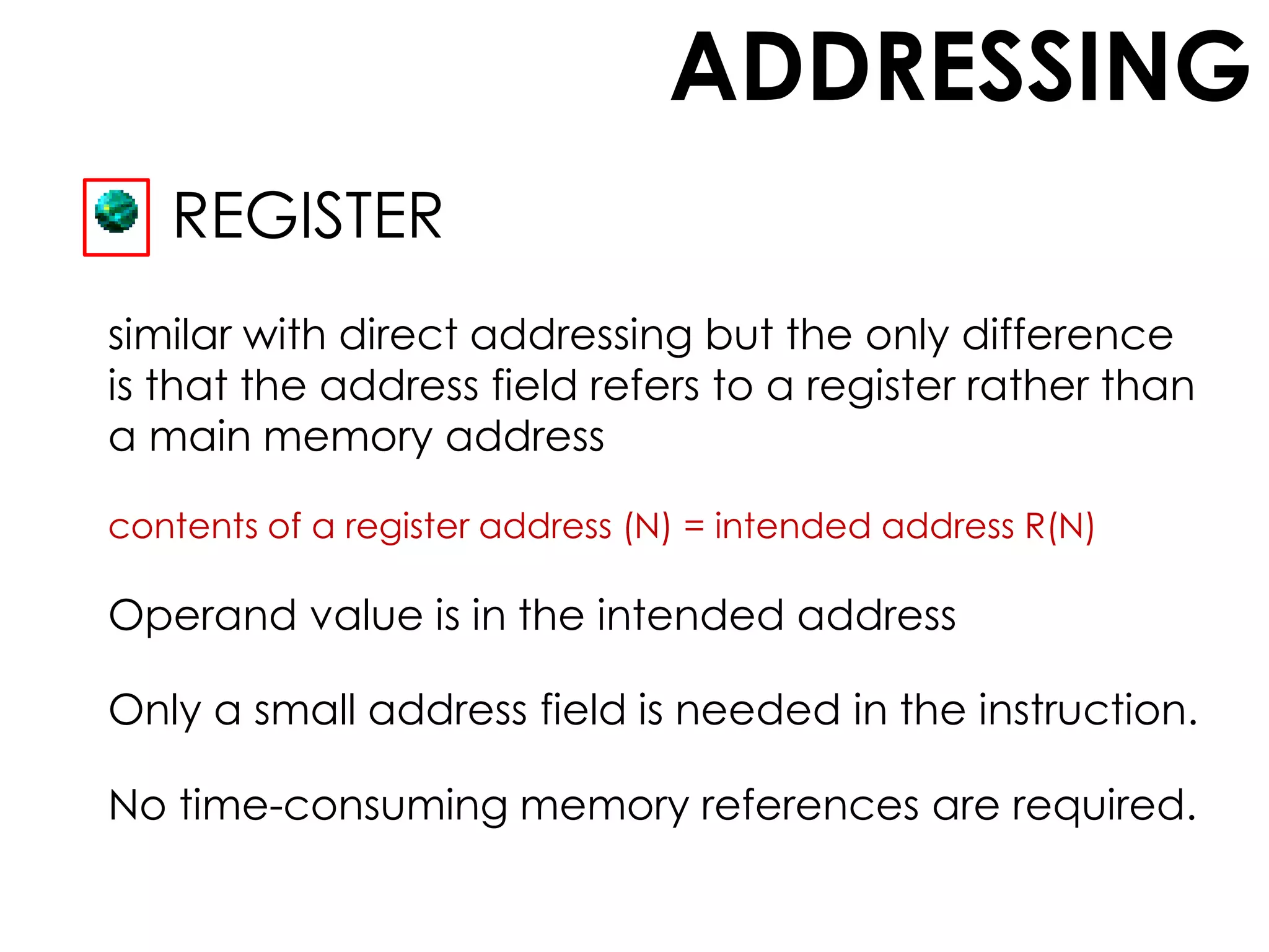
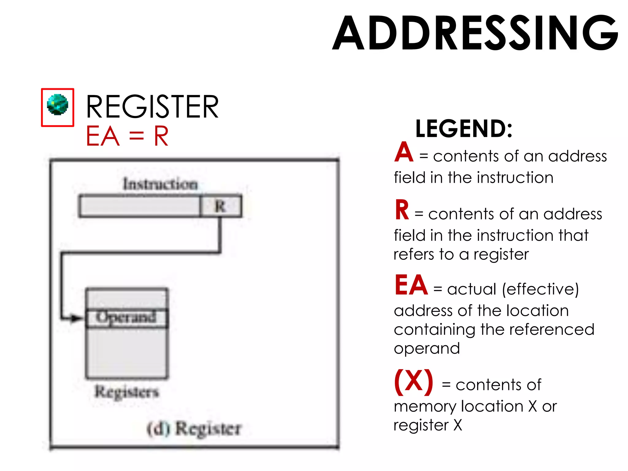
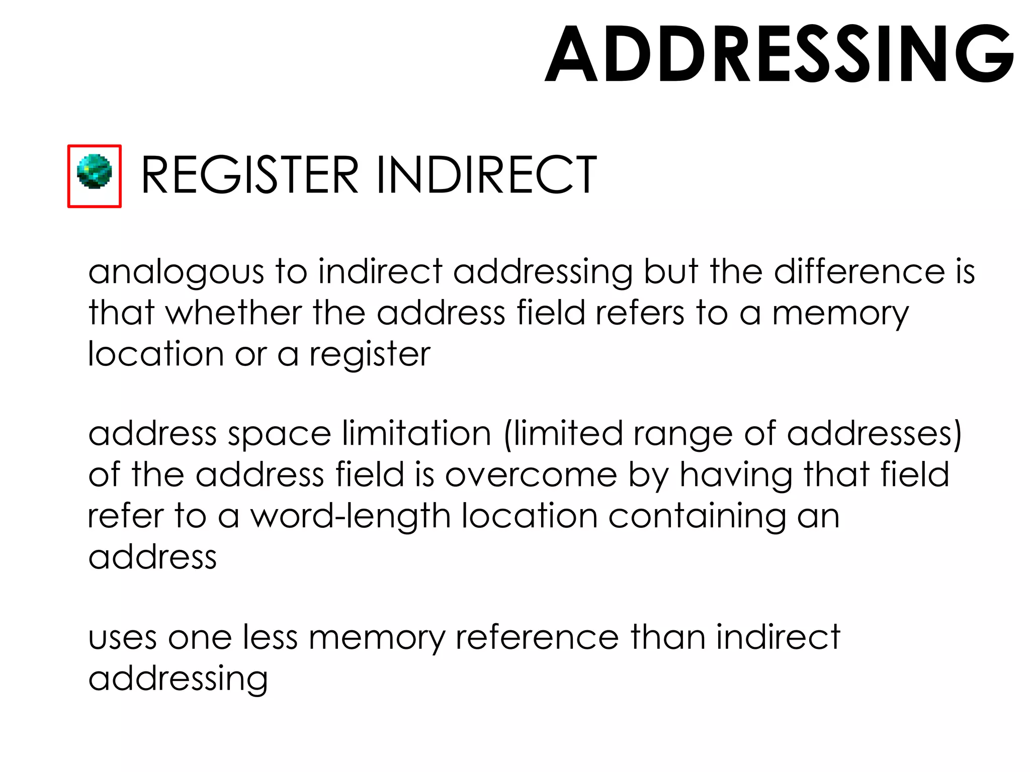
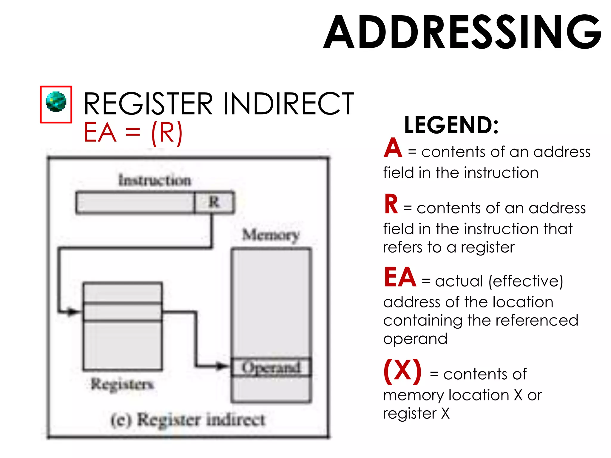
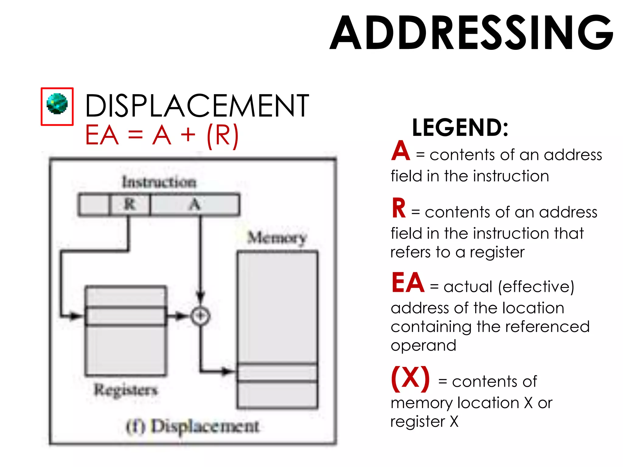
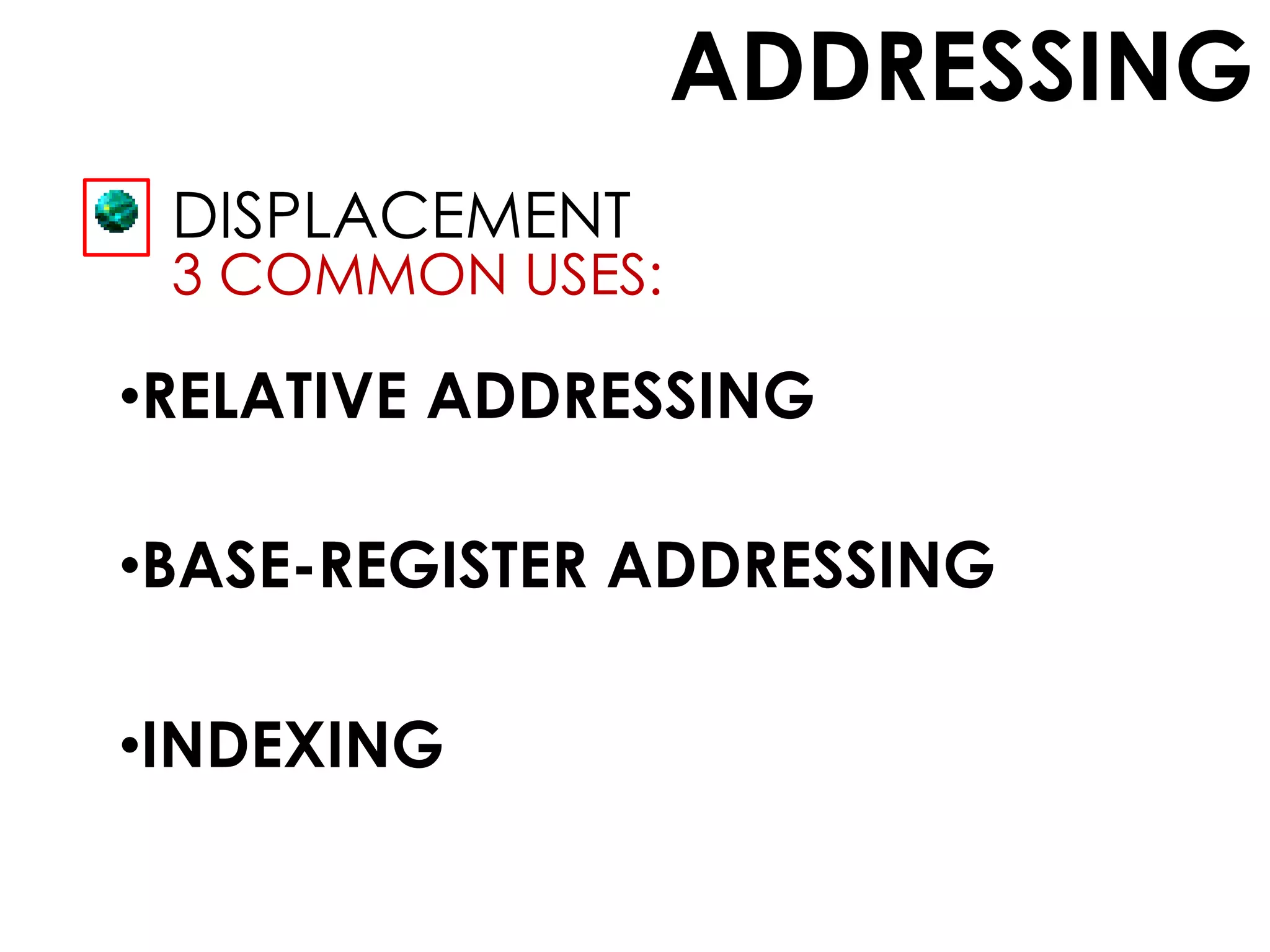
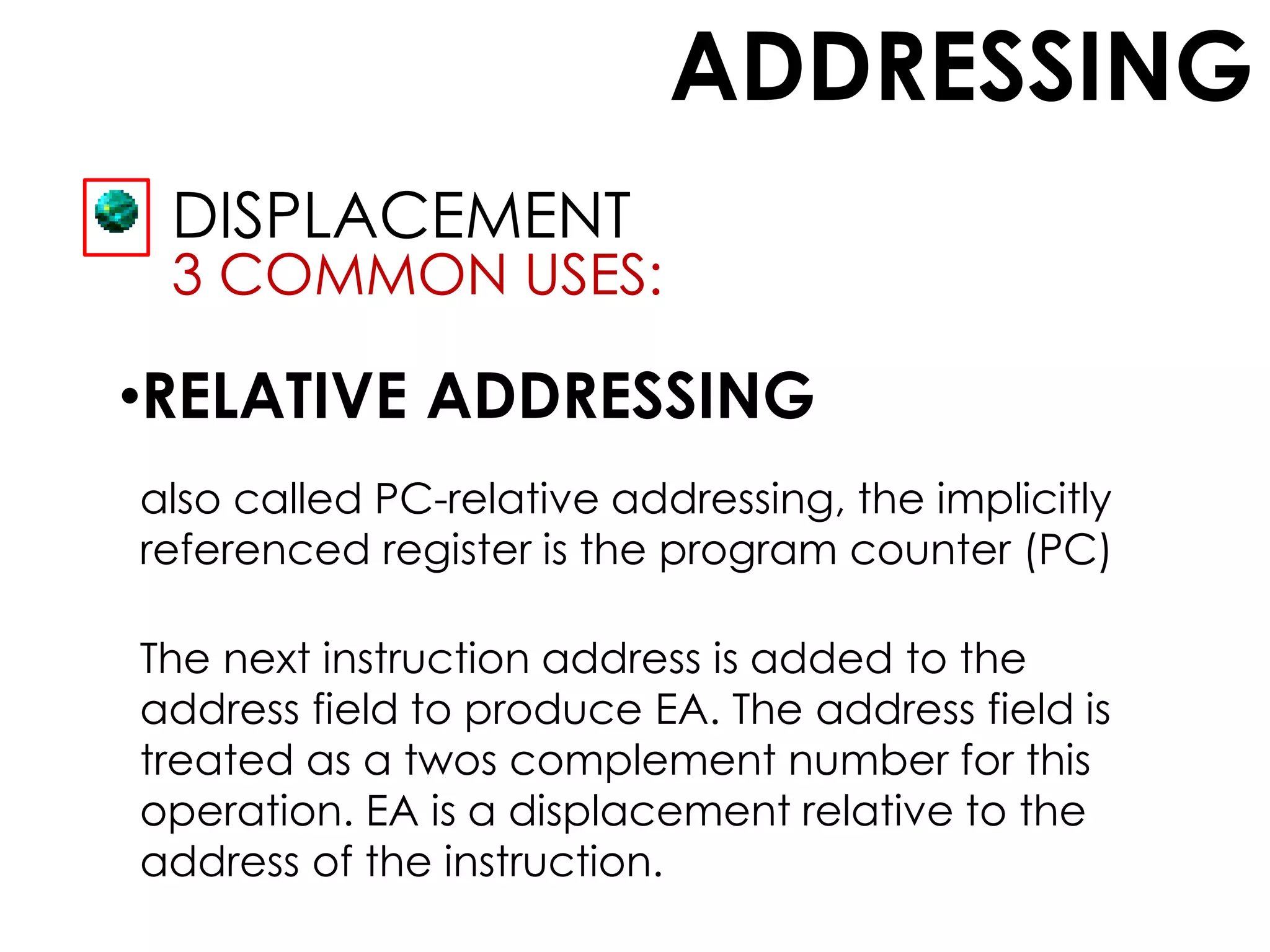
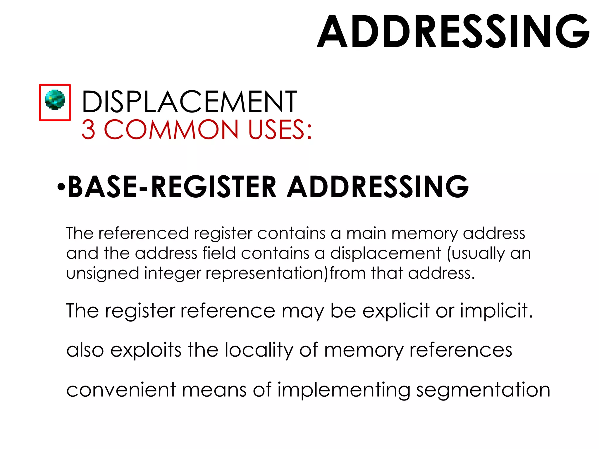
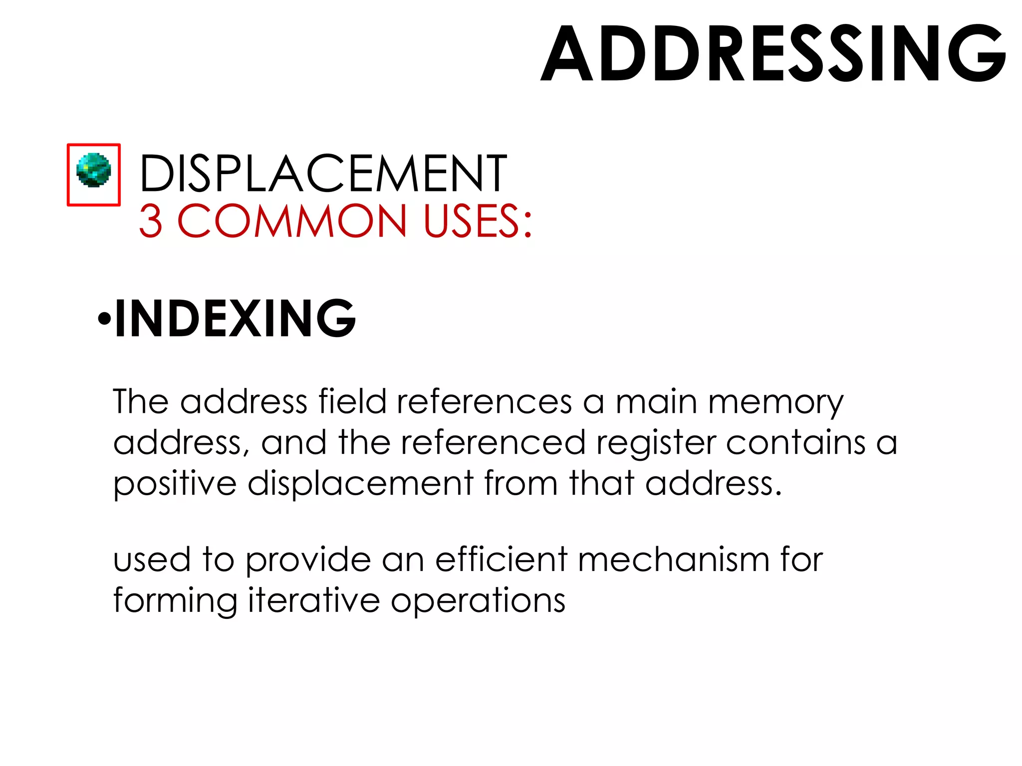
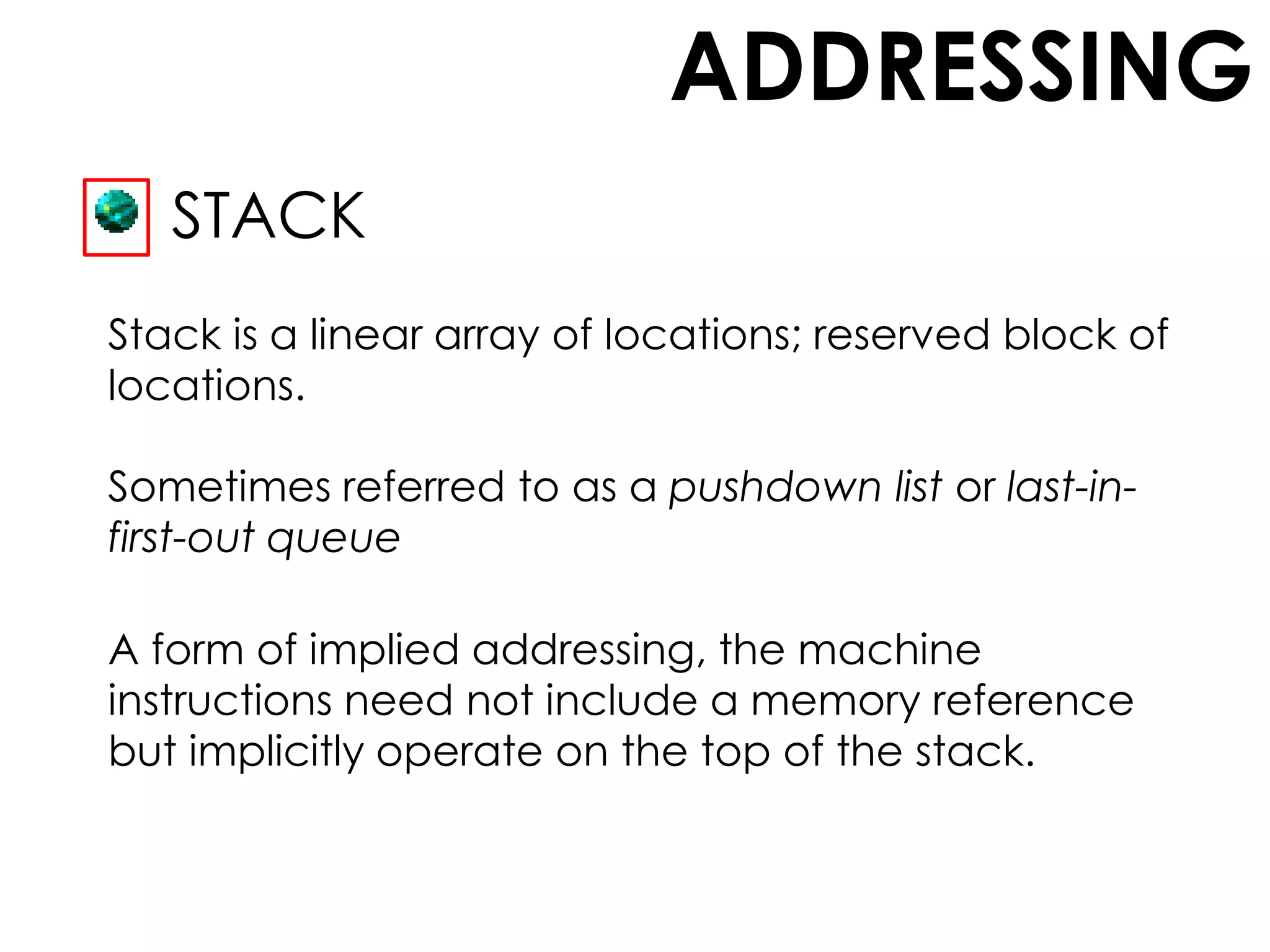
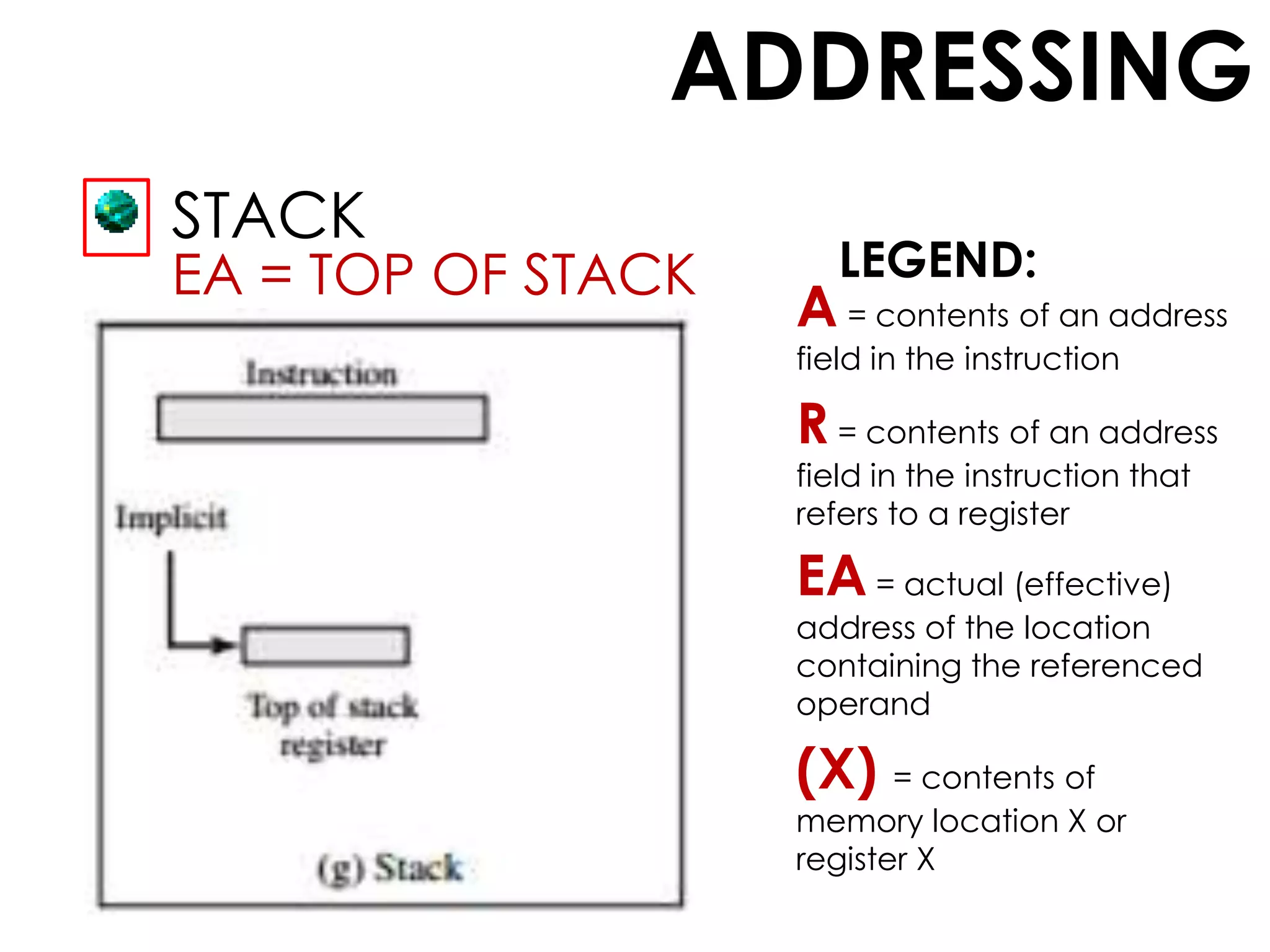
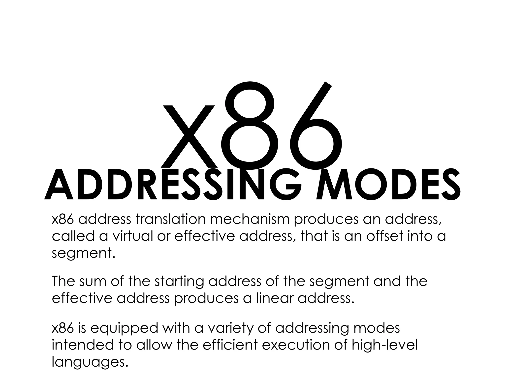
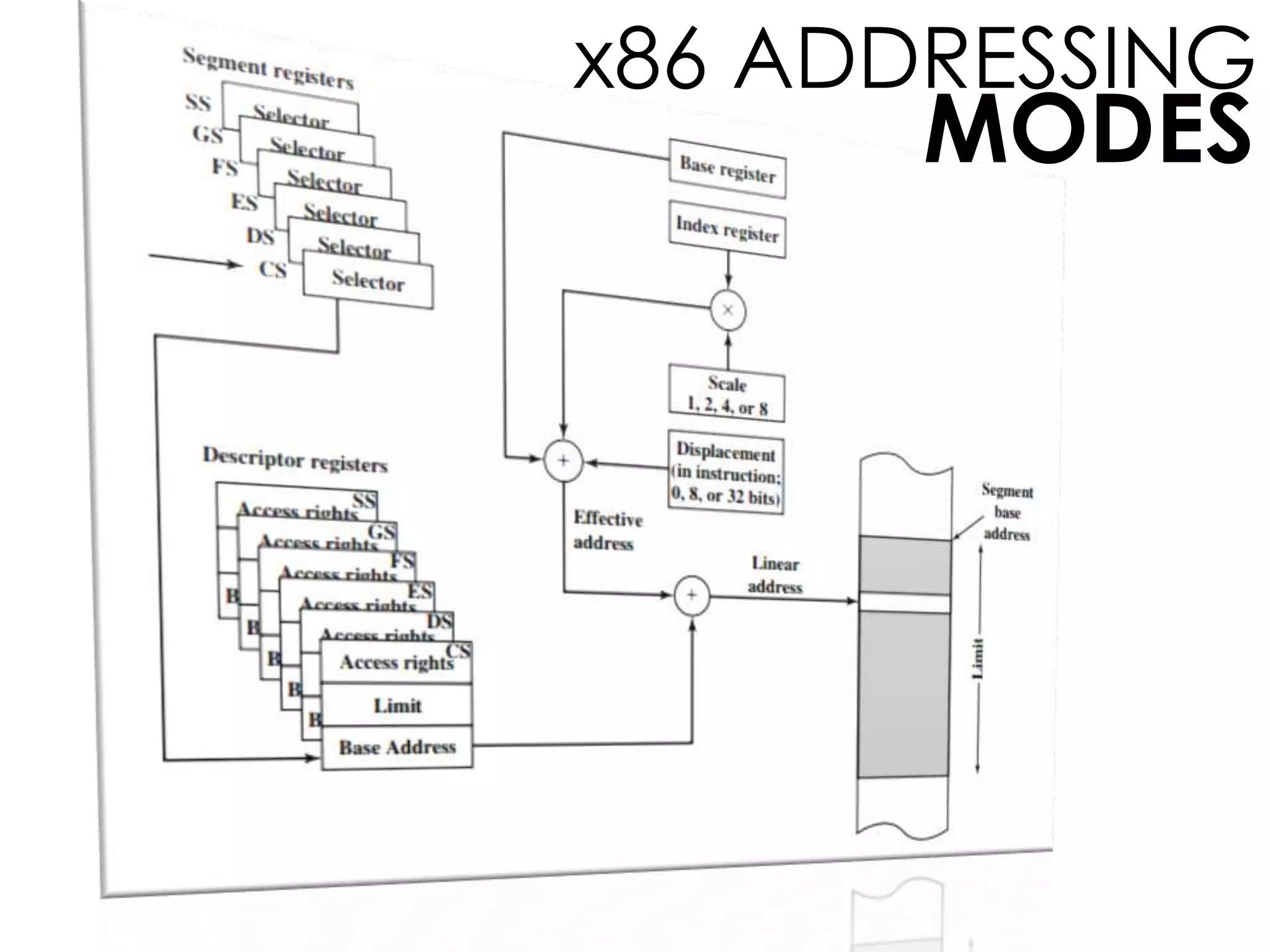
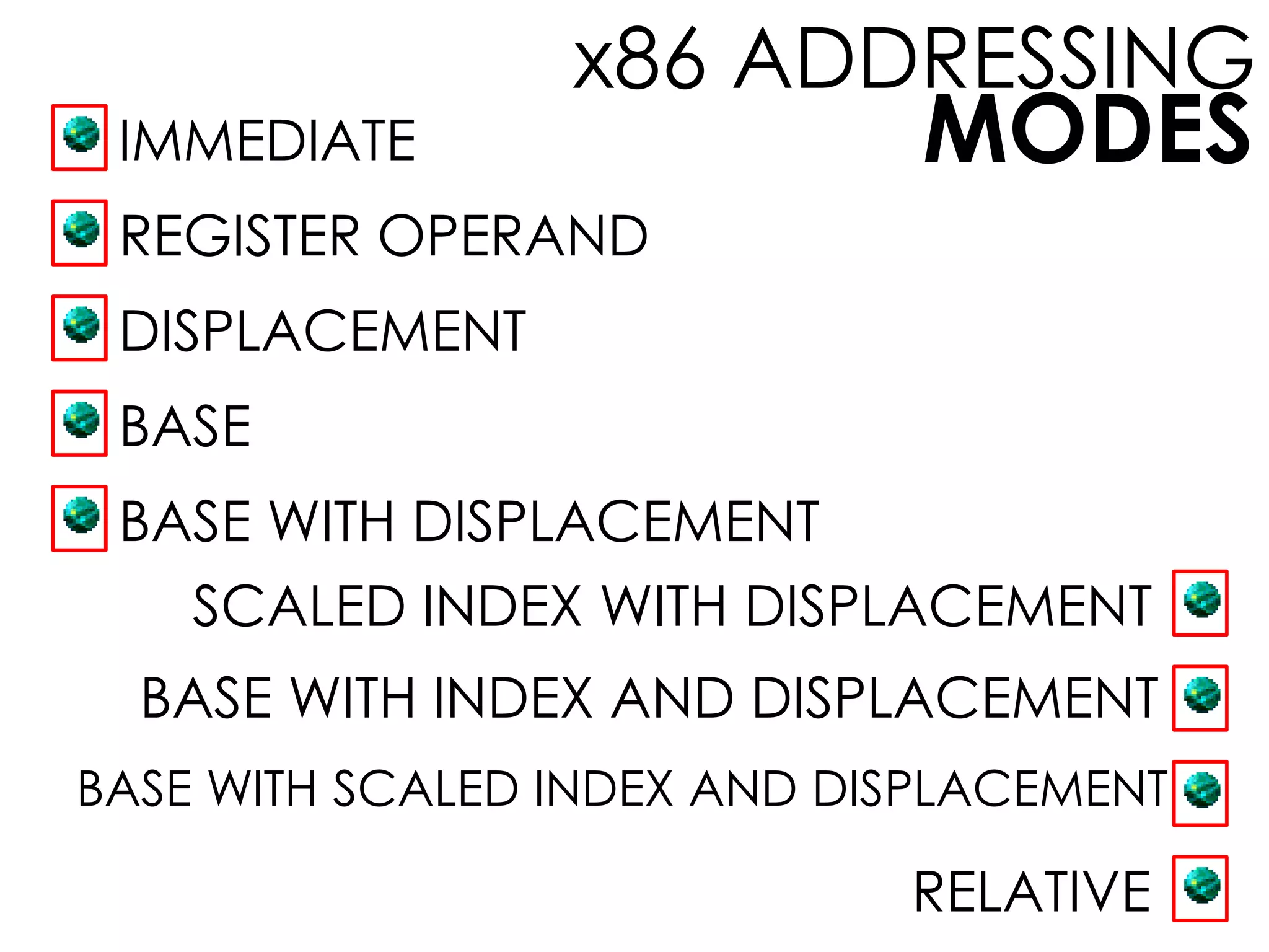
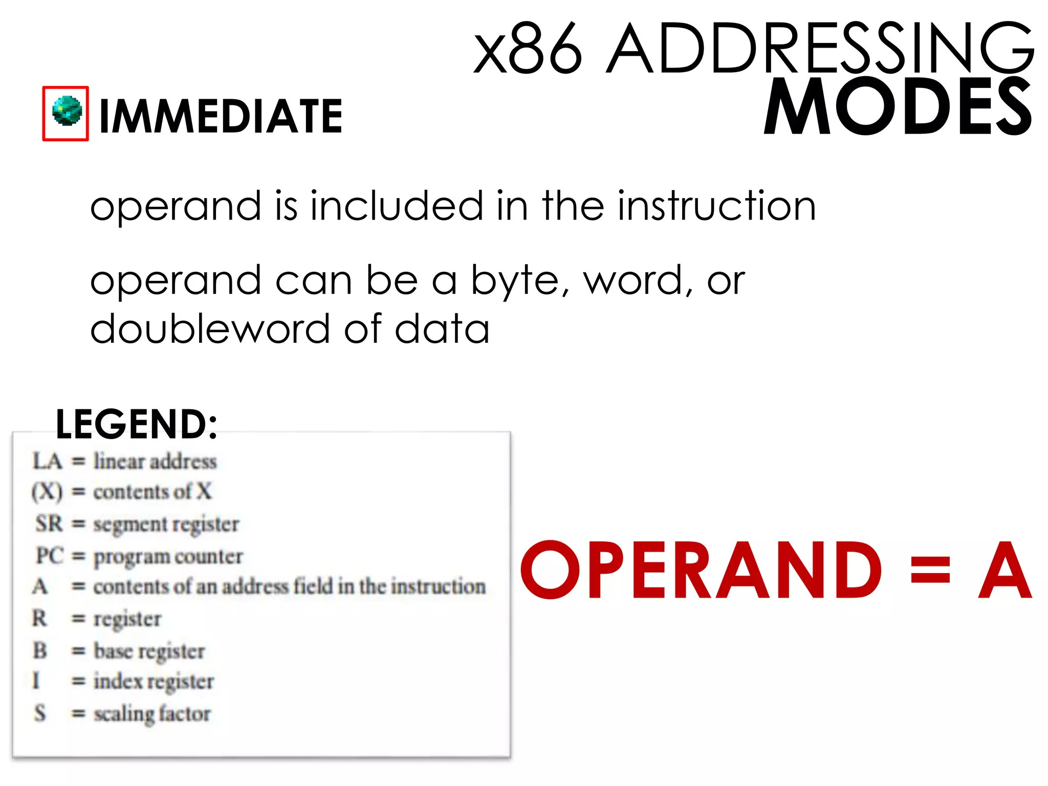
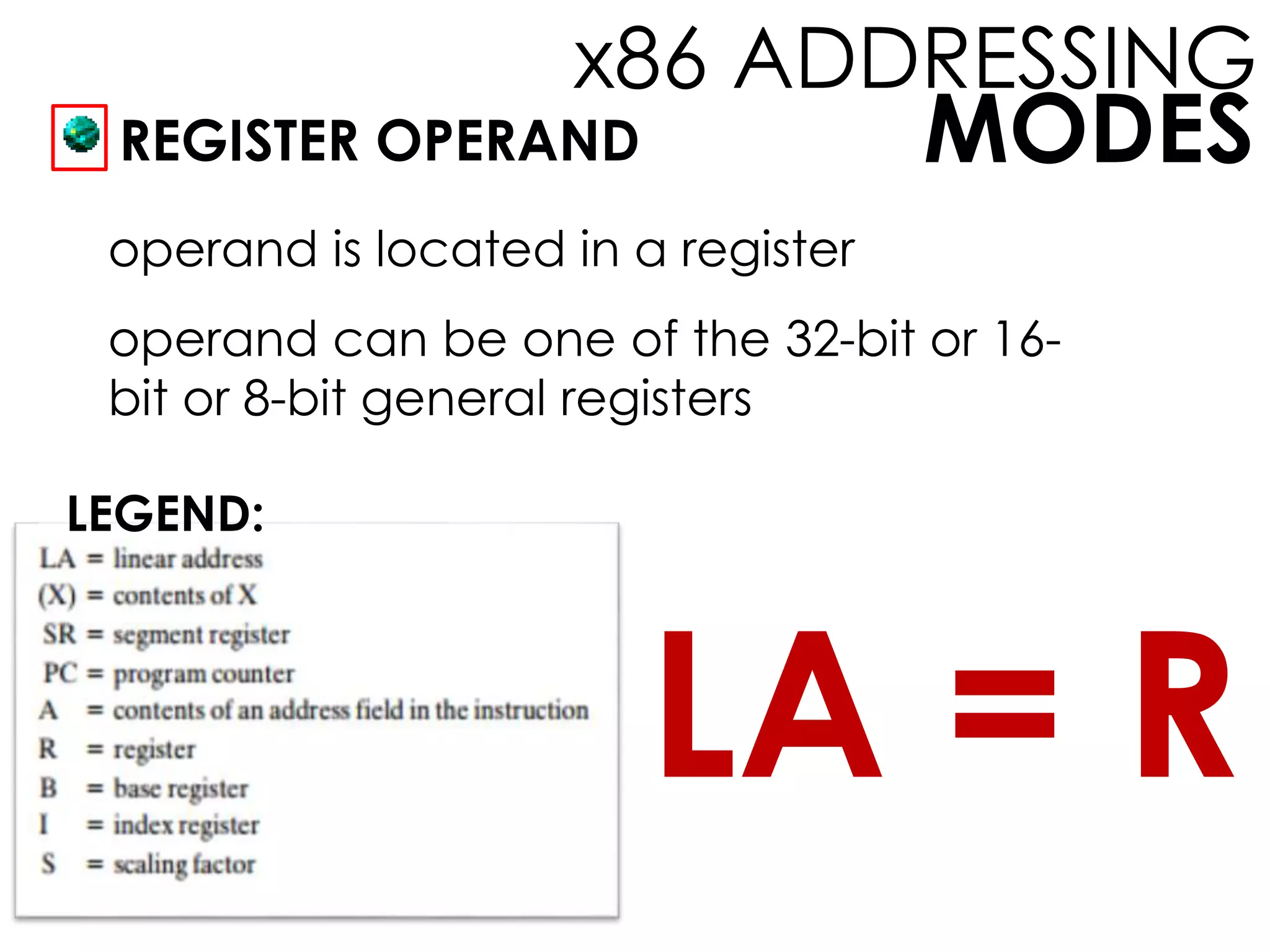
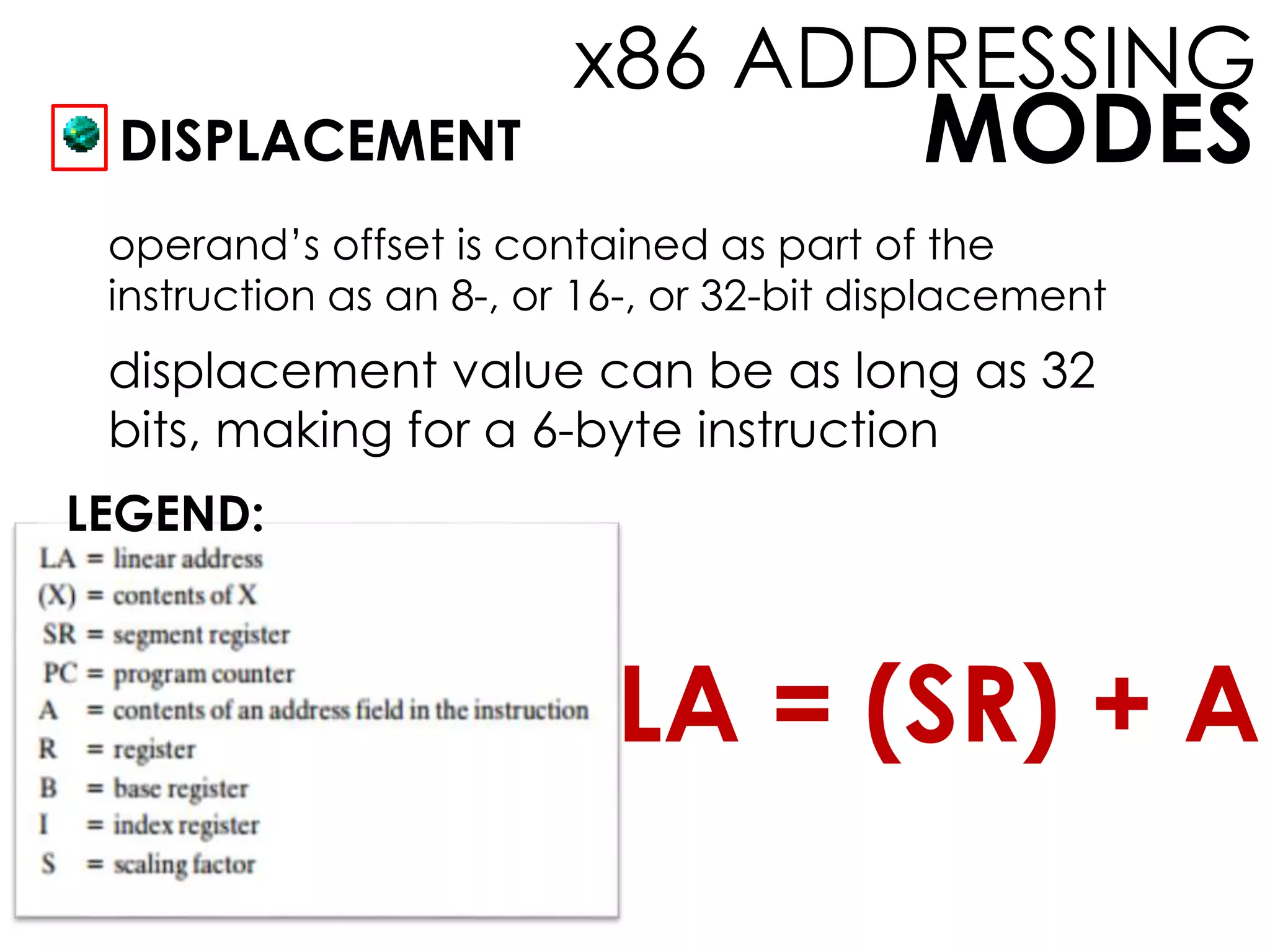
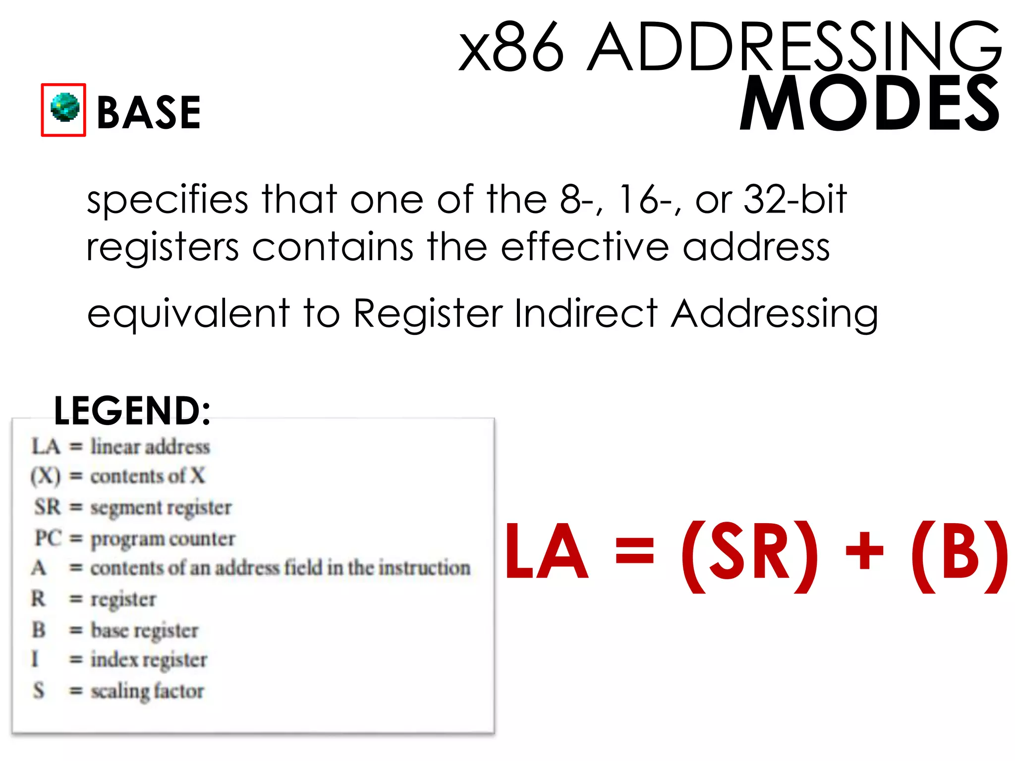
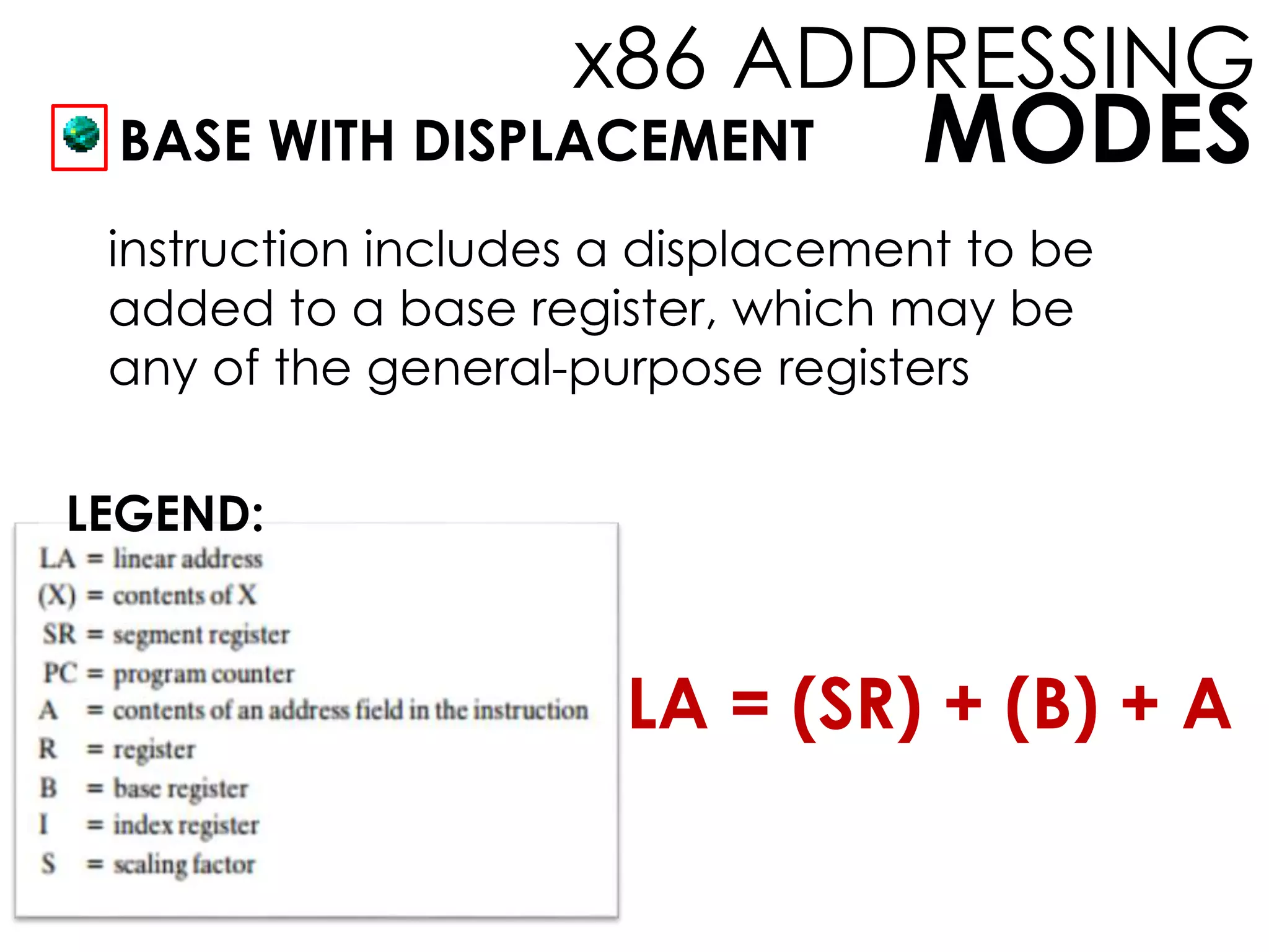
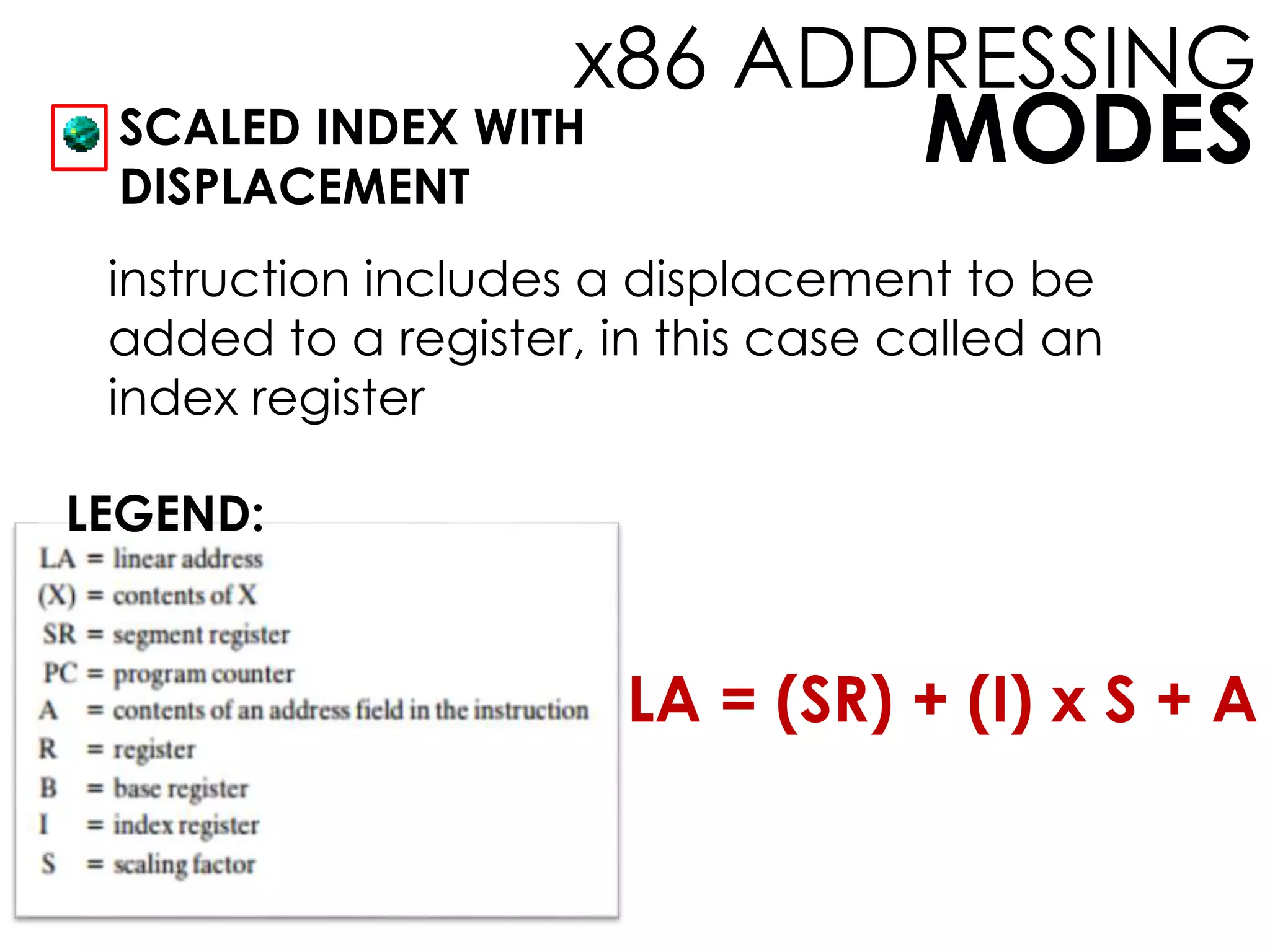
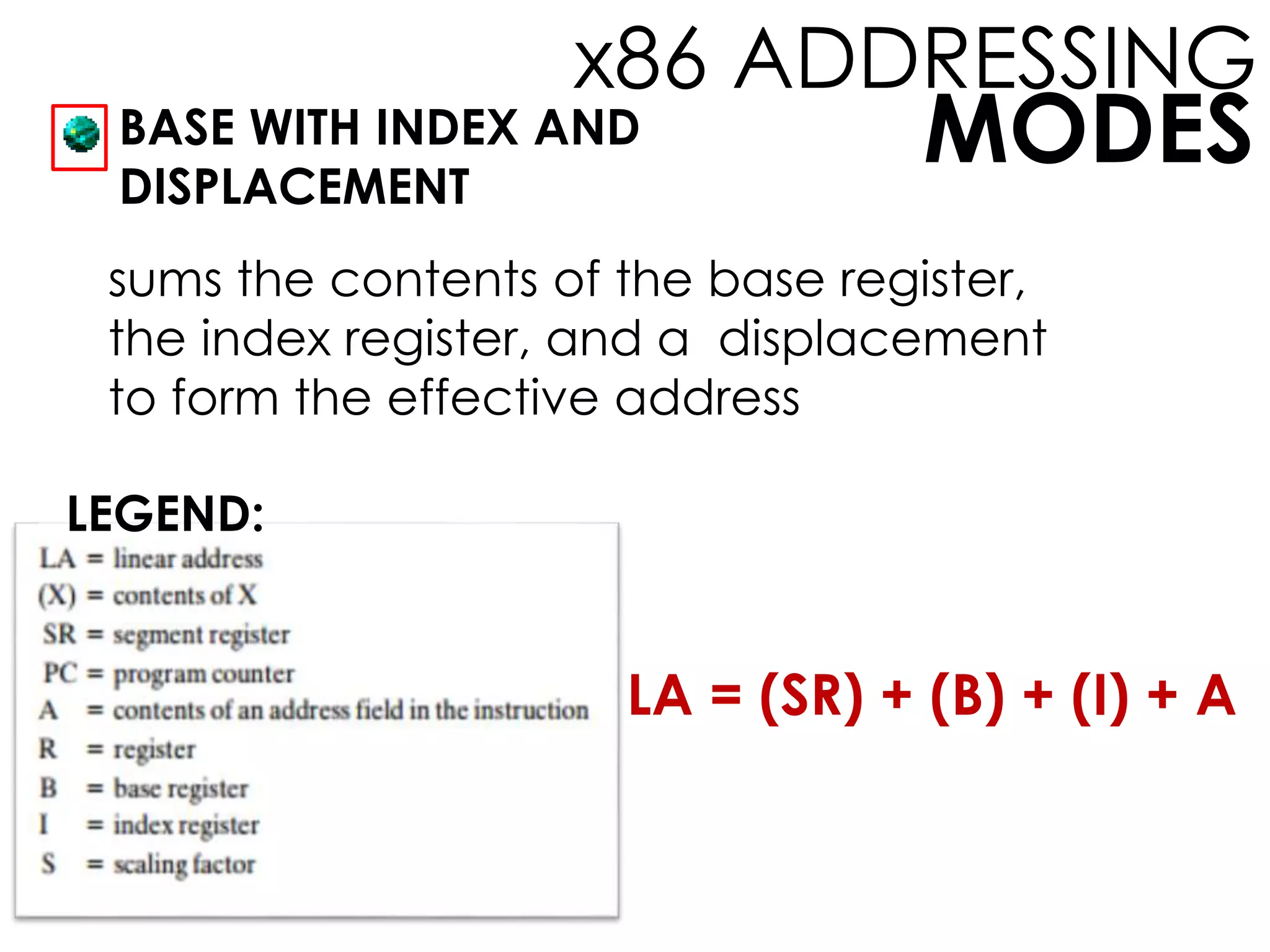
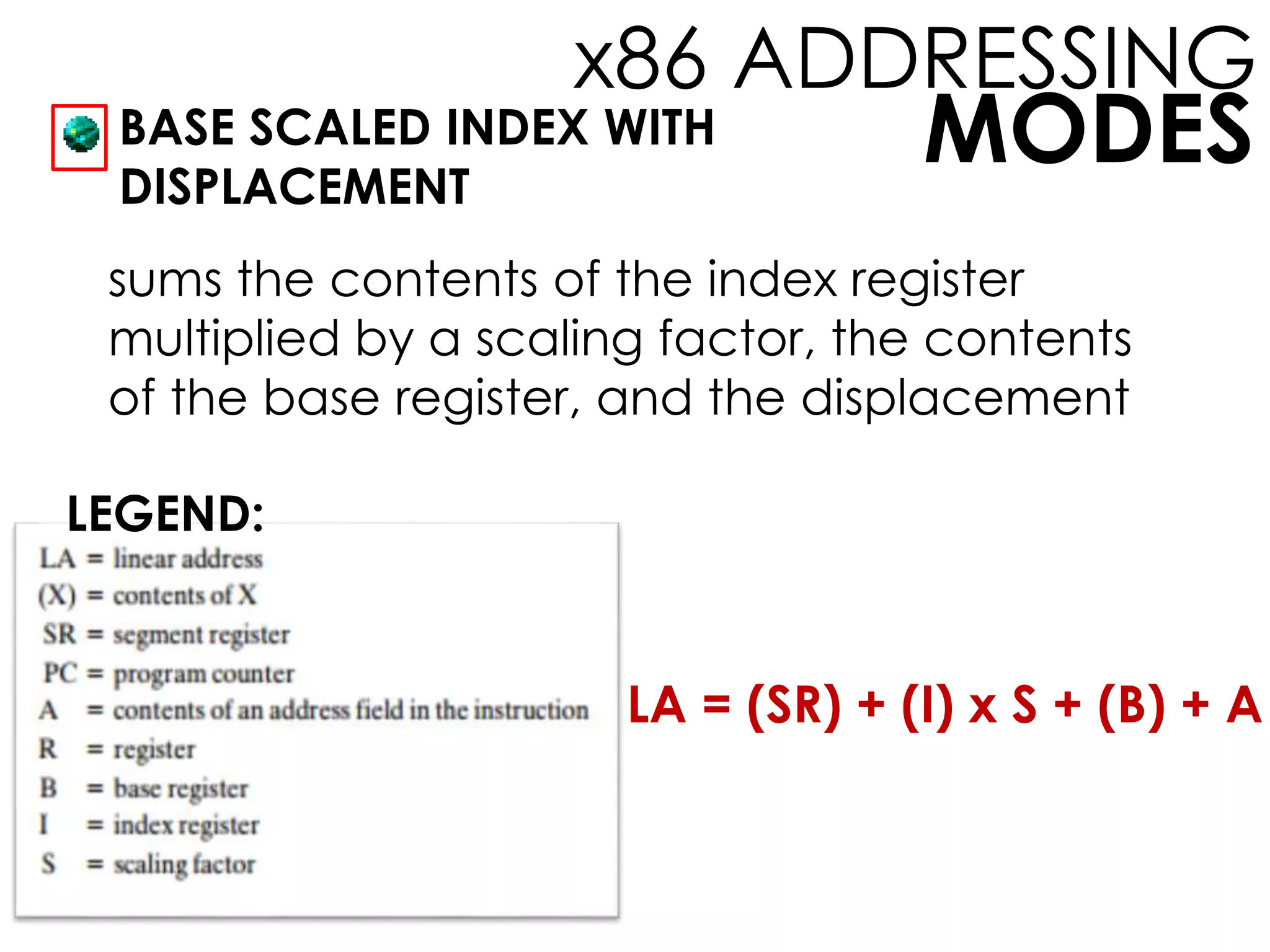
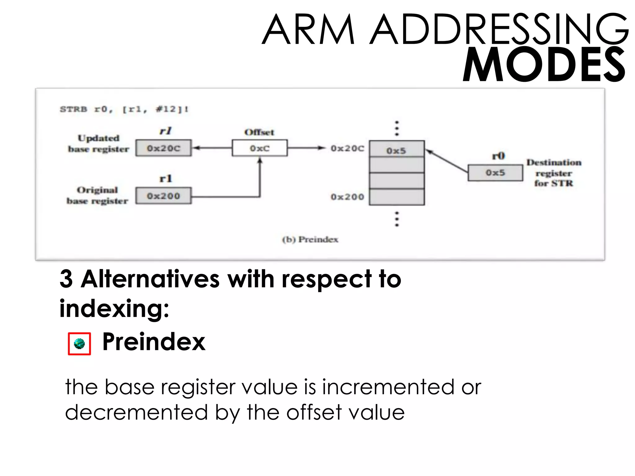
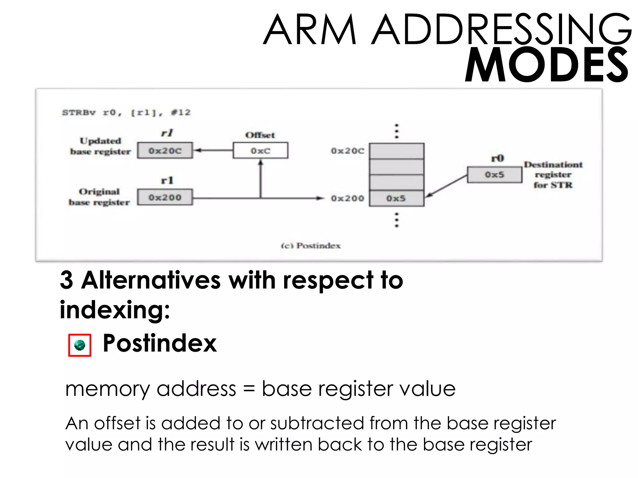
The document discusses different addressing modes used in instruction sets, including immediate, direct, indirect, register, register indirect, displacement, and stack addressing. It also covers addressing modes for x86 and ARM architectures. Key addressing modes include immediate (operand in instruction), register (operand in register), displacement (address plus offset), base (contents of base register), and register indirect (contents of register used as address). Addressing modes balance the number of opcodes, operands, registers, and address range represented in instructions.