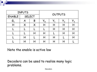
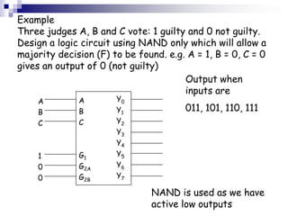
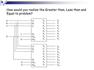
Decoders

                         Digital Logic and Software
                         Applications
                         Level 4
© University of Wales Newport 2009 This work is licensed under a Creative Commons Attribution 2.0 License.
The following presentation is a part of the level 4 module -- Digital Logic and Signal Principles. This resources is a part of the 2009/2010
Engineering (foundation degree, BEng and HN) courses from University of Wales Newport (course codes H101, H691, H620, HH37 and 001H).
This resource is a part of the core modules for the full time 1st year undergraduate programme.

The BEng & Foundation Degrees and HNC/D in Engineering are designed to meet the needs of employers by placing the emphasis on the
theoretical, practical and vocational aspects of engineering within the workplace and beyond. Engineering is becoming more high profile, and
therefore more in demand as a skill set, in today’s high-tech world. This course has been designed to provide you with knowledge, skills and
practical experience encountered in everyday engineering environments.


Contents
 Decoder
 Pin Arrangement & Truth Table
 Example Diagrams
 Credits


In addition to the resource below, there are supporting documents which should be used in combination with this
resource. Please see:
 Holdsworth B, Digital Logic Design, Newnes 2002
 Crisp J, Introduction to Digital Systems, Newnes 2001


                                                                 Decoders
Decoder


For a general description of decoder, please refer to

      http://en.wikipedia.org/wiki/Decoder


                        Decoders
Example: A 3-to-8 Line Single Bit Decoder
 G1
                               The inputs G1, G2A and G2B
G2A
                               must be of the correct logical
G2B                            value for the AND gate to
                               generate a 1 (this is G1 = 1,
A
                       Y0
                               G2A = G2B = 0)
B
C
                               If these are not correct each
                               of the NAND gates generates
                       Y1      a 1 out. It is worth noting at
                               this point that the outputs Y0
                               – Y7 are active low i.e. a 0 on
                       Y2      the output indicates an
                               activated output.
                            Decoders
The 8 NAND gates now have all eight combinations of the
three inputs A, B and C.
The Y0 NAND has not A, not B and not C so when A = B = C
= 0 then Y0 = 0 as long as the G inputs are of the correct
logic levels.
The other NANDs have other combinations – Y2 not A, B
and not C (010) and this would make Y2 = 0.

The integrated circuit that performs this function is a
74LS138.

Similar to this is the 74LS139 which contains 2 two to
four line decodes which work in a similar way. These have a
G1 input only and this must be at logic 0 for the outputs to
be activated.
                            Decoders
Pin Arrangement & Truth Table 74138

http://upgrade.kongju.ac.kr/data/ttl/74138.html


                      Decoders
Pin Arrangement 74139


http://upgrade.kongju.ac.kr/data/ttl/74139.html


                      Decoders
INPUTS
                                      OUTPUTS
ENABLE     SELECT
  G1      A      B     Y0             Y1   Y2   Y3
   H      X      X     H              H    H    H
   L      L      L     L              H    H    H
   L      L      H     H              L    H    H
   L      H      L     H              H    L    H
   L      H      H     H              H    H    L


Note the enable is active low


Decoders can be used to realise many logic
problems.
                           Decoders
Example
Three judges A, B and C vote: 1 guilty and 0 not guilty.
Design a logic circuit using NAND only which will allow a
majority decision (F) to be found. e.g. A = 1, B = 0, C = 0
gives an output of 0 (not guilty)
                                       Output when
                                       inputs are
    A         A        Y0
    B         B        Y1              011, 101, 110, 111
    C         C        Y2
                       Y3
                       Y4
    1         G1       Y5
    0         G2A      Y6
    0         G2B      Y7

                               NAND is used as we have
                               active low outputs
A 4-to-16 line decoder can be constructed in the
following way:
A                A      Y0          Y0
B                B      Y1          Y1
C                C      Y2          Y2
                        Y3          Y3
                        Y4          Y4
          1      G1     Y5          Y5
D                G2A    Y6          Y6
          0      G2B    Y7          Y7


                 A      Y0          Y8
                 B      Y1          Y9
                 C      Y2          Y10
                        Y3          Y11
                        Y4          Y12
                 G1     Y5          Y13
          0      G2A    Y6          Y14
          0      G2B    Y7          Y15

                         Decoders
How would you realise the Greater than, Less than and
Equal to problem?

A                A      Y0       Y0
B                B      Y1       Y1
C                C      Y2       Y2
                        Y3       Y3
                        Y4       Y4
         1       G1     Y5       Y5
D                G2A    Y6       Y6
         0       G2B    Y7       Y7


                 A      Y0       Y8
                 B      Y1       Y9
                 C      Y2       Y10
                        Y3       Y11
                        Y4       Y12
                 G1     Y5       Y13
         0       G2A    Y6       Y14
         0       G2B    Y7       Y15
This resource was created by the University of Wales Newport and released as an open educational resource
through the Open Engineering Resources project of the HE Academy Engineering Subject Centre. The Open
Engineering Resources project was funded by HEFCE and part of the JISC/HE Academy UKOER programme.


© 2009 University of Wales Newport


This work is licensed under a Creative Commons Attribution 2.0 License.

The JISC logo is licensed under the terms of the Creative Commons Attribution-Non-Commercial-No Derivative Works 2.0 UK: England &
Wales Licence. All reproductions must comply with the terms of that licence.

The HEA logo is owned by the Higher Education Academy Limited may be freely distributed and copied for educational purposes only,
provided that appropriate acknowledgement is given to the Higher Education Academy as the copyright holder and original publisher.

The name and logo of University of Wales Newport is a trade mark and all rights in it are reserved. The name and logo should not be
reproduced without the express authorisation of the University.


                                                                 Decoders

Decoders student

  • 1.
    Decoders Digital Logic and Software Applications Level 4 © University of Wales Newport 2009 This work is licensed under a Creative Commons Attribution 2.0 License.
  • 2.
    The following presentationis a part of the level 4 module -- Digital Logic and Signal Principles. This resources is a part of the 2009/2010 Engineering (foundation degree, BEng and HN) courses from University of Wales Newport (course codes H101, H691, H620, HH37 and 001H). This resource is a part of the core modules for the full time 1st year undergraduate programme. The BEng & Foundation Degrees and HNC/D in Engineering are designed to meet the needs of employers by placing the emphasis on the theoretical, practical and vocational aspects of engineering within the workplace and beyond. Engineering is becoming more high profile, and therefore more in demand as a skill set, in today’s high-tech world. This course has been designed to provide you with knowledge, skills and practical experience encountered in everyday engineering environments. Contents  Decoder  Pin Arrangement & Truth Table  Example Diagrams  Credits In addition to the resource below, there are supporting documents which should be used in combination with this resource. Please see:  Holdsworth B, Digital Logic Design, Newnes 2002  Crisp J, Introduction to Digital Systems, Newnes 2001 Decoders
  • 3.
    Decoder For a generaldescription of decoder, please refer to http://en.wikipedia.org/wiki/Decoder Decoders
  • 4.
    Example: A 3-to-8Line Single Bit Decoder G1 The inputs G1, G2A and G2B G2A must be of the correct logical G2B value for the AND gate to generate a 1 (this is G1 = 1, A Y0 G2A = G2B = 0) B C If these are not correct each of the NAND gates generates Y1 a 1 out. It is worth noting at this point that the outputs Y0 – Y7 are active low i.e. a 0 on Y2 the output indicates an activated output. Decoders
  • 5.
    The 8 NANDgates now have all eight combinations of the three inputs A, B and C. The Y0 NAND has not A, not B and not C so when A = B = C = 0 then Y0 = 0 as long as the G inputs are of the correct logic levels. The other NANDs have other combinations – Y2 not A, B and not C (010) and this would make Y2 = 0. The integrated circuit that performs this function is a 74LS138. Similar to this is the 74LS139 which contains 2 two to four line decodes which work in a similar way. These have a G1 input only and this must be at logic 0 for the outputs to be activated. Decoders
  • 6.
    Pin Arrangement &Truth Table 74138 http://upgrade.kongju.ac.kr/data/ttl/74138.html Decoders
  • 7.
  • 8.
    INPUTS OUTPUTS ENABLE SELECT G1 A B Y0 Y1 Y2 Y3 H X X H H H H L L L L H H H L L H H L H H L H L H H L H L H H H H H L Note the enable is active low Decoders can be used to realise many logic problems. Decoders
  • 9.
    Example Three judges A,B and C vote: 1 guilty and 0 not guilty. Design a logic circuit using NAND only which will allow a majority decision (F) to be found. e.g. A = 1, B = 0, C = 0 gives an output of 0 (not guilty) Output when inputs are A A Y0 B B Y1 011, 101, 110, 111 C C Y2 Y3 Y4 1 G1 Y5 0 G2A Y6 0 G2B Y7 NAND is used as we have active low outputs
  • 10.
    A 4-to-16 linedecoder can be constructed in the following way: A A Y0 Y0 B B Y1 Y1 C C Y2 Y2 Y3 Y3 Y4 Y4 1 G1 Y5 Y5 D G2A Y6 Y6 0 G2B Y7 Y7 A Y0 Y8 B Y1 Y9 C Y2 Y10 Y3 Y11 Y4 Y12 G1 Y5 Y13 0 G2A Y6 Y14 0 G2B Y7 Y15 Decoders
  • 11.
    How would yourealise the Greater than, Less than and Equal to problem? A A Y0 Y0 B B Y1 Y1 C C Y2 Y2 Y3 Y3 Y4 Y4 1 G1 Y5 Y5 D G2A Y6 Y6 0 G2B Y7 Y7 A Y0 Y8 B Y1 Y9 C Y2 Y10 Y3 Y11 Y4 Y12 G1 Y5 Y13 0 G2A Y6 Y14 0 G2B Y7 Y15
  • 12.
    This resource wascreated by the University of Wales Newport and released as an open educational resource through the Open Engineering Resources project of the HE Academy Engineering Subject Centre. The Open Engineering Resources project was funded by HEFCE and part of the JISC/HE Academy UKOER programme. © 2009 University of Wales Newport This work is licensed under a Creative Commons Attribution 2.0 License. The JISC logo is licensed under the terms of the Creative Commons Attribution-Non-Commercial-No Derivative Works 2.0 UK: England & Wales Licence. All reproductions must comply with the terms of that licence. The HEA logo is owned by the Higher Education Academy Limited may be freely distributed and copied for educational purposes only, provided that appropriate acknowledgement is given to the Higher Education Academy as the copyright holder and original publisher. The name and logo of University of Wales Newport is a trade mark and all rights in it are reserved. The name and logo should not be reproduced without the express authorisation of the University. Decoders