SHRI MADHWA VADIRAJAINSTITUTE OF
TECHNOLOGY AND MANAGEMENT
Microcontroller
18EC46
Venugopala Rao A S
Dept. of CSE
venugopalrao.cs@sode-edu.in
2.
8051 Instruction Set
•Module 2:
• Addressing modes
• Data Transfer Instructions
• Arithmetic Instructions
• Logical Instructions
• Branch Instructions
• Bit Manipulation Instructions
• Simple ALP examples (without loops)to use these instructions
2
7/25/2022 18EC46
3.
8051 Instruction Set
•The general structure of an 8051 instruction
• Label: mnemonic operand/s ; comments
• label allows the program to access a line of code by a name.
• All labels must start with an alphabetic character and end with a colon.
• E.g.: BACK: add A, B ; the word BACK is a label.
• mnemonic specifies the actual instruction to the microcontroller.
• E.g.: MOV A, B ; the keyword MOV is the mnemonic.
• operand/s indicates the parameters on which the mnemonic operates.
• E.g.: mov A, B ;A and B are the operands.
• Comment field is used to describe the program.
3
7/25/2022 18EC46
4.
8051 Instruction Set
•Length of an instruction:
• The instructions written in assembly language are translated into a machine code known
as opcode (operational code) to be executed by the CPU.
• Depending upon the number of bytes present in each instruction in the machine
language, the instructions are classified into 3 categories namely: 1-byte instruction, 2-
byte instruction and 3-byte instruction
• 1-byte instruction: An instruction which has only the mnemonic and the operands
• E.g.: mov A, B
• 2-byte instruction: has a mnemonic along with an 8 bit data/address explicitly specified.
• E.g.: mov A, #05H
• mov A, 50H
• 3-byte instruction: has a mnemonic along with a 16 bit data/address explicitly specified.
• Example: mov DPTR, #8000H
• LJMP 2AB5H
4
7/25/2022 18EC46
5.
8051 Instruction Set
•Addressing modes:
• The various ways by which the destination and source operand/s of an instruction are
specified are called addressing modes
• We have the following types of addressing modes.
• Immediate addressing mode.
• Register addressing mode/ Bank addressing mode.
• Direct addressing mode.
• Indirect addressing mode.
• Indexed addressing mode.
• Relative addressing mode.
• Absolute addressing mode.
• Long addressing mode.
• Bit direct addressing mode.
• Bit inherent addressing mode.
5
7/25/2022 18EC46
6.
8051 Instruction Set
•Immediate addressing mode:
• In this the source operand is a constant.
• As the name implies, the data is immediately available after the opcode in the instruction.
• The symbol ‘#’ is used to specify immediate addressing mode.
• E.g.: MOV A, #56H
• ADD A, #15
• MOV DPTR, #8000H
• Register addressing/ Bank addressing mode:
• In this, the names of registers are used as a part of instruction to access the data stored in them.
• Registers A, DPH, DPL and R0-R7 (of current register bank) may be used as a part of the
instruction.
• The selection of a register bank is decided by two bits (RS1 and RS0) of the Program Status
Word (PSW) register.
• E.g.: MOV A, R1
• ADD A, R7
6
7/25/2022 18EC46
7.
8051 Instruction Set
•Direct addressing mode:
• In this, the address of a memory location is specified in the instruction.
• most often used the direct addressing mode to access RAM locations 30 – 7FH
• All 128 bytes of internal RAM and SFR‟s can be addressed directly using the byte
addresses assigned to each.
• Example: MOV A, 40H
MOV R0, 80H
• Indirect addressing mode:
• In this, a memory Pointer register (either R0 or R1) is used to hold the 8 bit address of an
Internal RAM memory location that is used to access data.
• The mnemonic symbol ‘@’ is used to specify indirect addressing mode.
• Example: MOV A, @R0
MOV @R1, A
7
7/25/2022 18EC46
8.
8051 Instruction Set
Note:
Incase of external data memory access, either R0 OR R1 (256 bytes)/ DPTR(64KB) is
used as memory pointer register.
Example: MOVX A, @R0 (only 256 bytes of external memory can be accessed)
MOVX A, @DPTR (64KB of external memory can be accessed)
• Indexed addressing mode:
• This addressing mode is used to access data elements of “look-up table” located in the
Program memory (ROM).
• In this addressing mode either the PC register or the DPTR register is used to hold the
base address of the table and the accumulator is used to hold the table entry
number(Index).
• The 16-bit address of the table entry in program memory is then formed by adding the
accumulator data to the base address in either PC or DPTR.
• Example: MOVC A, @A+DPTR
• MOVC A, @A+PC
8
7/25/2022 18EC46
9.
8051 Instruction Set
•Relative addressing mode:
• This is used with certain jump instructions.
• The relative address, often referred to as an offset, is an 8 bit signed number,
which is automatically added to the PC register to make the address of the next
instruction.
• The 8 bit signed offset value gives an address range of +127 to -128 locations.
• E.g.: SJMP 50H
• JC 20H
9
7/25/2022 18EC46
10.
8051 Instruction Set
•Absolute addressing mode:
• In this mode, a jump or a call can be made only within 2KB memory space
• This addressing mode is used only by the AJMP and ACALL instructions.
• The program memory of 64KB is divided into 32 pages and the size of each page
is 2KB.
• For any page the address boundary is such that the most significant 5 bits of the
address will be the same and the least significant 11 bits of the address will
change.
• Therefore, the absolute addressing will determine only the least significant 11 bits
of the program counter.
• Example: AJMP 5789H
• ACALL 5789H
10
7/25/2022 18EC46
11.
8051 Instruction Set
•Long addressing mode:
• The long addressing within the 8051 is used only with the instructions LJMP and
LCALL.
• The address specifies a full 16 bit destination address so that a jump or a call can
be made to a location within a 64KB code memory space.
• Example: LJMP 1234H
• LCALL 1234H
11
7/25/2022 18EC46
12.
8051 Instruction Set
•Bit direct addressing mode:
• Some of the 8051 instructions accesses one bit of data of a register instead of the
entire 8 bit data of the register.
• Such instructions are said to have bit addressing mode.
• In bit direct addressing, the address of the bit is directly specified in the
instruction.
• Example: CLR b (where “b” is bit address 00h-7Fh or bit addressable SFR)
• SETB b
• Bit inherent addressing mode:
• In bit inherent addressing mode it is implied that the specified bit is a carry bit.
• Example: CLR C
• SETB C
12
7/25/2022 18EC46
13.
8051 Instruction Set
•INSTRUCTION SET
• Classified based on the function they perform into the following 5 categories.
• Data Transfer Instructions
• Arithmetic Instructions
• Logical Instructions
• Boolean Variable manipulation or bit manipulation Instructions
• Program Branching Instructions
• Data Transfer Instructions:
• These instructions deal with transferring (copying) the data from source to
destination.
• The general form of Move instruction is: MOV destination, source
13
7/25/2022 18EC46
14.
8051 Instruction Set
•Here the destination and the source can either be a register or a memory location.
• The various forms of Move instruction are:
• MOV Rn, A
• MOV addr, A
• MOV @RP, A MOV A, Rn MOV addr, Rn
• MOV A, addr MOV Rn, addr MOV addr, addr
• MOV @RP, addr MOV A, #D8 MOV Rn, #D8
• MOV addr, #D8 MOV @RP,#D8 MOV A, @RP
• MOV addr, @RP
14
7/25/2022 18EC46
15.
8051 Instruction Set
•MOV A ,Rn
• Copies the contents of register Rn (of the current register bank) into the
accumulator.
• Register addressing mode.
• 1 byte
• E.g.: MOV A , R2 ; copy the contents of register R2 into the accumulator.
15
7/25/2022 18EC46
16.
8051 Instruction Set
•MOV A ,addr
• Copy the contents of the internal RAM address (addr) into the destination register.
• Direct addressing mode.
• 2 bytes
• E.g.: MOV A , 30H ; copy the contents of RAM location with address 30H into
the accumulator.
16
7/25/2022 18EC46
17.
8051 Instruction Set
•MOV A ,#D8
• Copy the immediate 8-bit data into the destination.
• Immediate addressing mode.
• 2 bytes
• E.g.: MOV A , #45H ; copy the 8 bit data (45H) into the accumulator
17
7/25/2022 18EC46
18.
8051 Instruction Set
•MOV A ,@Rp
• Copy the contents of the internal RAM
location pointed by Rp into the
Accumulator.
• The address of RAM location is
present in register Rp.
• Rp can be either R1 or R0.
• Indirect addressing mode.
• 1 byte
• E.g. : MOV A ,@R0
18
7/25/2022 18EC46
19.
8051 Instruction Set
•External Data Moves:
• RAM and ROM can be expanded by adding external memory chips to the 8051.
• The external memory can be as large as 64KB for each of the RAM and ROM
memory areas.
• Instructions that access this external memory always use indirect addressing
mode.
• NOTE: All external data moves must use the accumulator.
• The various instructions are
• a) MOVX A ,@Rp b) MOVX A ,@DPTR c) MOVX @Rp ,A
• d) MOVX @DPTR, A
19
7/25/2022 18EC46
20.
8051 Instruction Set
•MOVX A ,@Rp
• Copy the contents of external RAM location pointed by Rp into the accumulator.
• The address of RAM location is present in register Rp.
• Rp can be either R1 or R0.
• Indirect addressing mode.
• 1 byte
• E.g.: MOVX A ,@R1
20
7/25/2022 18EC46
21.
8051 Instruction Set
•MOVX A ,@DPTR
• Copy the contents of external RAM address stored in register DPTR into the
accumulator.
• Indirect addressing mode.
• 1 byte
• E.g.: MOVX A, @DPTR
21
7/25/2022 18EC46
22.
8051 Instruction Set
•Code Memory (Read-Only) Data Moves:
• The data can also be stored in the program ROM. Access to this data is made
possible by using index addressing and the accumulator in conjunction with the PC
or the DPTR as shown.
• MOVC A , @A+DPTR
• Copies the code byte, found at the ROM into accumulator.
• The address is formed by adding contents of accumulator and the DPTR
• Uses index addressing mode.
• 1 byte
22
7/25/2022 18EC46
8051 Instruction Set
•MOVC A ,@A+PC
• Copies the code byte, found at the ROM into accumulator.
• The address is formed by adding the content of PC and accumulator.
• Uses indirect addressing mode.
• 1 byte
24
7/25/2022 18EC46
25.
8051 Instruction Set
•Data Exchange instructions:
• MOV, PUSH and POP instructions transfer the data in a single direction
• i,e. from source to destination, leaving the source unaltered.
• Exchange instructions move the data in two directions
• i.e. from source to destination and vice-versa.
• The various forms of exchange instructions are:
• XCH A ,Rn
• XCH A ,addr
• XCH A ,@Rp
• XCHD A ,@Rp (exchange digits)
25
7/25/2022 18EC46
26.
8051 Instruction Set
•XCH A ,Rn
• Exchange data bytes between the accumulator and the register Rn(of current
register bank)
• Register addressing mode
• 1 byte
• E.g.: XCH A , R4 ; exchange bytes between register R4 and the Accumulator
26
7/25/2022 18EC46
27.
8051 Instruction Set
•XCH A , addr
• Exchange data bytes between the accumulator and the memory location (addr)
• Direct addressing mode
• 2 bytes
• E.g.: XCH A, 30H ; exchange the contents of the Accumulator and the memory
location(70H).
27
7/25/2022 18EC46
28.
8051 Instruction Set
•XCH A ,@Rp
• Exchange data bytes between the
accumulator and the memory location
whose address is in register Rp. (Rp
can be either R0 or R1).
• Indirect addressing mode
• 1 byte
• E.g.: XCH A , @R0
• exchange the contents of the
accumulator and the memory location
whose address is in register R0.
28
7/25/2022 18EC46
29.
8051 Instruction Set
•XCHD A ,@Rp
• Exchange the lower nibble(lower 4 bits ) in the accumulator along with the lower
nibble of the RAM memory location pointed by Rp. (Rp can be either R0 or R1)
• Upper nibbles are unaltered
• Indirect addressing mode
• 1 byte
• E.g.: XCHD A , @R0
29
7/25/2022 18EC46
30.
8051 Instruction Set
•Stack operation: Push and Pop
• PUSH addr
• Increment the SP and then copy
the data from the internal
RAM address (addr) to the
internal RAM address
contained in SP
• Direct addressing mode.
• 2 bytes
• E.g.: PUSH 30H
30
7/25/2022 18EC46
31.
8051 Instruction Set
•POP addr
• Copies the data from the stack memory to the internal RAM whose
address is specified in the instruction.
• The contents SP are decremented.
• Direct addressing mode.
• 2 bytes
• E.g.: POP 30H
31
7/25/2022 18EC46
8051 Instruction Set
•Arithmetic Instructions:
• These perform mathematical calculations on data as per the requirement.
• The various arithmetic operations performed in 8051 are discussed below
• Incrementing and Decrementing operations:
• These instructions increment or decrement the contents of the destination by one.
• The general form of the instruction is INC/DEC destination where the
destination can be either a register or a memory location.
• Let us go through the various forms of increment and decrement instructions one
by one
33
7/25/2022 18EC46
34.
8051 Instruction Set
•INC A
• Increment the contents of the accumulator by one.
• Register addressing mode
• 1 byte
• INC Rn
• Increment the contents of the register Rn ,of the current register bank by one.
• Register addressing mode
• 1 byte
• E.g. INC R3
34
7/25/2022 18EC46
35.
8051 Instruction Set
•INC addr
• Increment the contents of the direct address(addr) by one.
• Direct addressing mode
• 2 bytes
• E.g.: INC 30H
• add one to the contents of the address 30H.
35
7/25/2022 18EC46
36.
8051 Instruction Set
•INC @Rp
• Increment the contents of the memory location pointed by Rp by one. Rp can be
either R0 or R1.
• Indirect addressing mode
• 1 byte
• E.g.: INC @R0; add one to the contents of the memory location whose address is
in R0
36
7/25/2022 18EC46
37.
8051 Instruction Set
•INC DPTR
• Increment the contents of the data pointer register by one.
• Register addressing mode
• 1 byte
• Decrement instructions
• DEC A
• Decrement the contents of the accumulator by one.
• Register addressing mode
• 1 byte
37
7/25/2022 18EC46
38.
8051 Instruction Set
•DEC Rn
• Decrement the contents of the register Rn ,of the current register bank by one.
• Register addressing mode
• 1 byte
• E.g.: DEC R2
• DEC addr
• Decrement the contents of the direct address(addr) by one.
• Direct addressing mode
• 2 bytes
• E.g.: DEC 50H
38
7/25/2022 18EC46
39.
8051 Instruction Set
•DEC @Rp
• Decrement the contents of the memory location whose address is in register Rp by
one. Rp can be either R0 or R1.
• Indirect addressing mode
• 1 byte
• E.g.: DEC @ R1
• Note:
• There is no instruction for decrementing DPTR.
• No Math flags (CY, AC, OV) are affected for increment and decrement
instructions.
39
7/25/2022 18EC46
40.
8051 Instruction Set
•Addition and Subtraction operations:
• Addition is performed using the accumulator as the destination.
• All math flags are affected.
• ADD A , Rn
• Add the contents of the register, Rn, to the contents of the accumulator ; store the
result in the accumulator.
• Register addressing mode
• 1 byte
• E.g.: ADD A , R5
• Flags affected: CY=0 ;AC=0; OV=0; P=1
40
7/25/2022 18EC46
41.
8051 Instruction Set
•ADD A , addr
• Add the contents of the internal RAM address (addr) to the contents of the
accumulator and store the result in the accumulator.
• Direct addressing mode
• 2 bytes
• E.g.: ADD A , 30H
• Flags affected: CY=0; AC=0; OV=0; P=1
41
7/25/2022 18EC46
42.
8051 Instruction Set
•ADD A , @Rp
• Add the contents of the internal RAM location ,whose address is in register Rp to
the contents of the accumulator and store the result in the accumulator.
• Indirect addressing mode
• 1 byte
• E.g.: ADD A , @R1
• Flags affected: CY=0;AC=0;OV=0;P=1.
42
7/25/2022 18EC46
43.
8051 Instruction Set
•ADD A , #D8
• Add the immediate data, D8 to the contents of the accumulator and store the result
in the accumulator.
• Immediate addressing mode
• 2 bytes
• E.g.: ADD A , #05H
• Flags affected: CY=0; AC=0; OV=0; P=1
43
7/25/2022 18EC46
44.
8051 Instruction Set
•ADDC A , Rn
• Add the contents of the register Rn(of the current register bank) and the contents
of the carry flag to the contents of the accumulator and store the result in
accumulator.
• Register addressing mode
• 1 byte
44
7/25/2022 18EC46
45.
8051 Instruction Set
•ADDC A , addr;
• Add the contents of the internal RAM and the contents of the carry flag to the
contents of the accumulator and store the result in accumulator.
• Direct addressing mode
• 2 bytes
• E.g.: ADDC A, 35H
• Flags affected: CY=0; AC=1; OV=0; P=0.
45
7/25/2022 18EC46
46.
8051 Instruction Set
•ADDC A , #D8
• Add the immediate data, D8 and the contents of the carry flag to the contents of
the accumulator and store the result in accumulator.
• Immediate addressing mode
• 2 bytes
• E.g.: ADDC A, #06H
• Flags affected: CY=0; AC=1; OV=0; P=1.
46
7/25/2022 18EC46
47.
8051 Instruction Set
•ADDC A , @Rp;
• Add the contents of the internal RAM along with the CARRY flag to the contents
of the accumulator and store the result in the accumulator.
• The address of the RAM is in the register Rp.
• The register Rp can be either R0 or R1.
• E.g.: ADDC A, @R1
• Flags affected:
• CY=0; AC=1;
• OV=0; P=0.
47
7/25/2022 18EC46
48.
8051 Instruction Set
•SUBTRACTION
• In the case of most microcontrollers, there are two commands for subtraction
• subtraction without borrow and subtraction with borrow.
• But the 8051 microcontroller has only one command; SUBB (subtraction without
borrow).
• So the carry flag has to be adjusted to perform subtraction with borrow.
• Subtraction with the carry flag set to 0
• There are three operations performed by the CPU to perform subtraction:
• Take 2’s complement of the subtrahend (source operand)
• Add to the minuend (A)
• Invert the carry
• Once these three operations are performed, the accumulator shows the result of the
subtraction operation.
48
7/25/2022 18EC46
49.
8051 Instruction Set
•Let us look at an example to get a better understanding of the whole process.
• CLR C ; makes CY=0
• MOV A, #3FH; loads 3FH into A
• MOV R3, #23H; loads 23H into R3
• SUBB A, R3 ; performs A-R3 and places the result in the accumulator
• If the carry flag is 0 after the execution of the SUBB command, then the result is
positive and negative if the value is 1.
49
7/25/2022 18EC46
50.
8051 Instruction Set
•The result of the SUBB operation is in 2’s complement format in the case of
negative numbers.
• To change this, the CPL (complement) and INC (increment) command is used.
• Subtraction with the carry flag set to 1
• In the case of 8-bit subtraction operations, the carry is not required, but for multi-
bit operations, it becomes very important to keep the carry bit in check.
• E.g.: subtract 1296H from 2762H.
50
7/25/2022 18EC46
51.
8051 Instruction Set
•CLRC
• MOVA, #62H; moves the lower nibble of minuend(62H) to the accumulator
• SUBB, #96H; subtracts the lower nibble of the subtrahend from the accumulator
• as 96H is greater than 62H there is a carry from the higher nibble) cy=1)
• MOV R6,A; stores the lower nibble result in R6
• MOVA,#27H; moves the upper nibble of minuend(27H) to the accumulator
• SUBBA,#12H; subtracts the lower nibble of the subtrahend(12H) from the
accumulator(as the CY bit is 1 the microcontroller performs 27H-12H-1)
• MOVR7,A; Stores the result in R7
51
7/25/2022 18EC46
52.
8051 Instruction Set
•The various subtraction instructions:
• SUBB A ,Rn; (A) (A)-(Rn)-(CY)
• Subtract the contents of the register Rn and the contents of the carry flag from the
contents of accumulator and store the result in accumulator.
• Register addressing mode
• 1 byte
• E.g.: SUBB A , R4
52
7/25/2022 18EC46
Flags affected: CY=1 ; AC=1 ; OV=0 ; P=0
53.
8051 Instruction Set
•SUBB A ,addr ; (A) (A)-(addr)-(CY)
• Subtract the contents of the internal RAM and the contents of the carry flag from
the contents of accumulator and store the result in accumulator.
• Direct addressing mode
• 2 bytes
• EX: SUBB A, 35H
• Flags affected: CY=1 ; AC=1 ; OV=0 ; P=0
53
7/25/2022 18EC46
54.
8051 Instruction Set
•SUBB A ,#D8 ;
• Subtract immediate data, D8 and the contents of the carry(borrow) flag from the
contents of accumulator and store the result in accumulator.
• Immediate addressing mode
• 2 bytes
• Example: SUBB A ,#05H
• Flags affected: CY=0 ; AC=1 ; OV=0 ; P=1
54
7/25/2022 18EC46
55.
8051 Instruction Set
•SUBB A ,@Rp ; (A) (A) – ((Rp)) – (CY)
• subtract the contents of the internal RAM location whose address is in register Rp
and also the contents of the carry flag from the accumulator and store the result in
accumulator.
• Indirect addressing mode
• 1 byte
55
7/25/2022 18EC46
56.
8051 Instruction Set
•Multiplication and Division operations
• 8051 supports only 8-bit by 8-bit multiplication.
• Uses registers A and B as both source and destination operands for the operation.
• One of the operands must be in A register and the other operand must be in B.
• The result of operation is stored in both A and B registers, the low order byte is
stored in A register and the high order byte is stored in B register
56
7/25/2022 18EC46
57.
8051 Instruction Set
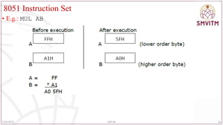
•MUL AB
• Multiply the contents of A and B registers and store the low order byte of the
product in register A and the high order byte of the product in register B.
• Flags affected: CY,OV
• Register addressing mode
• 1 byte
• NOTE:
• The carry flag is always cleared to 0.
• The overflow flag is set whenever the product A*B is greater than FFh
57
7/25/2022 18EC46
8051 Instruction Set
•Division:
• 8051 supports only byte –over- byte division.
• Division operation uses registers A(accumulator) and B as both source and
destination operands for the operation
• DIV AB
• Divide the contents of the register A by the contents of the register B.
• Store the integer part of the quotient in register A and the remainder in register B.
Flags affected: CY,OV
• Register addressing mode
• 1 byte
59
7/25/2022 18EC46
60.
8051 Instruction Set
•The carry flag is always cleared.
• The overflow flag is cleared to 0 unless register B holds 00H before division,
• indicating that division by zero is undefined.
• E.g.: DIV AB
60
7/25/2022 18EC46
61.
8051 Instruction Set
•BCD ADDITION
• BCD (Binary Coded Decimal): the numbers 0 to 9 represent the BCD numbers.
• There are two kinds of BCD numbers namely :
• Unpacked BCD numbers
• Packed BCD numbers
• In an Unpacked BCD number, the lower 4 bits of the number represent the BCD
number and the rest higher 4 bits are zeros.
• E.g.: 0000 1001 - the representation of unpacked BCD number 9.
• In a Packed BCD number, a single byte has two BCD numbers, one in the lower 4
bits and one in upper 4 bits.
• E.g.: 0110 0101 is the representation of packed BCD 65.
61
7/25/2022 18EC46
62.
8051 Instruction Set
•DAA ( decimal adjust for addition)
• The addition is done in ‘binary’ by the microcontroller.
• The result of this addition may not be correct when the data is BCD.
• Therefore, while BCD numbers are added, the result after the addition needs to be
corrected to represent the correct BCD value.
• Hence DA A instruction should be used immediately after performing addition of
BCD numbers.
• The result after DAA will represent the answer in correct BCD format.
62
7/25/2022 18EC46
63.
8051 Instruction Set
•Working of DAA instruction:
• The microcontroller checks the contents of accumulator.
• If the lower 4-bits of accumulator is greater than 9 or if auxiliary carry is set then
06 is added to accumulator and then the auxiliary carry is set.
• (A) (A)+06
• (AC) 1
• After the above modification, if the higher 4 bits of accumulator is greater than 9
or carry flag is set, then 60 is added to accumulator and carry flag is set.
• (A) (A) +60
• (CY) 1
• DA instruction works only after the ADD or ADDC instruction and not after the
INC instruction.
63
7/25/2022 18EC46
64.
8051 Instruction Set
•Logical instructions:
• Logical operations performed by the 8051 are the OR, AND, XOR and the NOT
• AND operation:
• The general form of AND instruction is: ANL destination, source
• The contents of the destination and the source are ANDed and the result is stored
in the destination.
• The destination is normally the accumulator; the source operand can be memory, a
Register or an immediate data.
• The various forms of AND instructions are:
• ANL A, Rn ANL addr, A ANL A, addr
• ANL addr, #D8 ANL A, #D8 ANL A, @Rp
64
7/25/2022 18EC46
65.
8051 Instruction Set
•ANL A, Rn
• Each bit of the accumulator is logically ANDed with the corresponding bit of
register Rn, of the current register bank and store the result in accumulator.
• Register addressing mode
• 1 Byte
• E.g.: ANL A, R3
65
7/25/2022 18EC46
66.
8051 Instruction Set
•ANL A, #D8
• Logically AND each bit of the accumulator with the corresponding bit of the
immediate data and store the result in accumulator.
• Immediate addressing mode
• 2 bytes
• ANL A, @Rp
• Logically AND each bit of the accumulator with the corresponding bit of the
immediate data and store the result in accumulator.
• Indirect addressing mode
• 1 Byte
66
7/25/2022 18EC46
67.
8051 Instruction Set
•ANL addr, A
• Logically AND each bit of the accumulator with the corresponding bit of the
contents of the internal RAM address (addr) and store the result in internal RAM
address (addr).
• Direct addressing mode
• 2 Bytes
• ANL addr, #D8
• Logically AND each bit of immediate data, D8 with the corresponding bit of the
contents of the internal RAM address (addr) and store the result in internal RAM
address (addr).
• Direct addressing mode
• 3 bytes
67
7/25/2022 18EC46
68.
8051 Instruction Set
•OR operation:
• The general form of OR instruction is: ORL destination, source
• The contents of the destination and the source are ORed and the result is stored in
the destination.
• The destination is normally the accumulator; the source operand can be in
memory, Register or an immediate data.
68
7/25/2022 18EC46
69.
8051 Instruction Set
•ORL A, Rn
• Logically OR each bit of accumulator with the corresponding bit of register Rn, of
the current register bank and store the result in accumulator.
• Register addressing mode
• 1 byte
• E.g.: ORL A, R3
69
7/25/2022 18EC46
70.
8051 Instruction Set
•ORL A, addr
• Logically OR each bit of accumulator with the corresponding bit of the contents of
the internal RAM address(addr) and store the result in accumulator.
• Direct addressing mode
• 2 bytes
• ORL A,#D8
• Logically OR each bit of accumulator with the corresponding bit of immediate
data, D8 and store the result in accumulator.
• Immediate addressing mode
• 2 bytes
70
7/25/2022 18EC46
71.
8051 Instruction Set
•ORL A, @Rp
• Logically OR each bit of accumulator with the corresponding bit of the contents of
the internal RAM address contained in register Rp and store the result in
accumulator.
• Indirect addressing mode
• 1 byte
• ORL addr,A
• Logically OR each bit of accumulator with the corresponding bit of the contents of
the internal RAM address (addr) and store the result in internal RAM address
(addr).
• Direct addressing mode
• 2 bytes
71
7/25/2022 18EC46
72.
8051 Instruction Set
•ORL addr, #D8
• Logically OR each bit of the contents of the internal RAM address (addr) with the
corresponding bit of the immediate data, D8 and store the result in internal RAM
address(addr).
• Direct addressing mode
• 3 bytes
• XOR operation:
• The general form of XOR instruction is: XRL destination, source
• The contents of the destination and the source are XORed and the result is stored in
• destination.
• The destination is normally the accumulator, the source operand can be in memory, a
Register or an immediate data
72
7/25/2022 18EC46
73.
8051 Instruction Set
•XRL A, Rn
• Logically XOR each bit of accumulator with the corresponding bit of register Rn,
of the current register bank and store the result in accumulator.
• Register addressing mode
• 1 byte
• E.g.: XRL A, R3
73
7/25/2022 18EC46
74.
8051 Instruction Set
•XRL A, addr
• Logically XOR each bit of accumulator with the corresponding bit of the contents
of the internal RAM address(addr) and store the result in accumulator.
• Direct addressing mode
• 2 bytes
• XRL A, #D8
• Logically XOR each bit of accumulator with the corresponding bit of immediate
data, D8 and store the result in accumulator.
• Immediate addressing mode
• 2 bytes
74
7/25/2022 18EC46
75.
8051 Instruction Set
•XRL A, @Rp
• Logically XOR each bit of accumulator with the corresponding bit of contents of
the internal RAM address contained in register Rp and store the result in
accumulator.
• Indirect addressing mode
• 1 byte
• XRL addr,A
• Logically XOR each bit of accumulator with the corresponding bit of the contents
of the internal RAM address (addr) and store the result in internal RAM address
(addr).
• Direct addressing mode
• 2 bytes
75
7/25/2022 18EC46
76.
8051 Instruction Set
•XRL addr, #D8
• Logically XOR each bit of the contents of the internal RAM address (addr) with
the corresponding bit of the immediate data, D8 and store the result in internal
RAM address(addr).
• Direct addressing mode
• 3 bytes
• Clear instruction:
• CLR A
• Clear the contents of accumulator.
• Register addressing mode
• 1 byte
• E.g.: CLR A
76
7/25/2022 18EC46
77.
8051 Instruction Set
•Complement instruction:
• CPL A
• Complement each bit of the accumulator, i.e. every 1 becomes a 0 and vice-versa.
• Register addressing mode
• 1 byte
• E.g.: CPL A
77
7/25/2022 18EC46
78.
8051 Instruction Set
•Rotate and Swap instruction:
• There are rotate instructions that operate only on a byte, or a byte and the carry
flag to allow 8 bit(only a byte) and 9 bit(a byte and a carry flag) shift register
operations.
• Swap instructions are used to exchange the lower and higher nibbles in a byte.
• The rotate and the swap instructions are limited to the Accumulator.
• The various rotate instructions are:
• RLA RLC A RR A RRC A
• SWAPA
78
7/25/2022 18EC46
79.
8051 Instruction Set
•RL A
• Rotate the contents of the accumulator 1 bit position to the left.
• The Most Significant Bit (MSB) becomes the Least Significant Bit (LSB).
79
7/25/2022 18EC46
80.
8051 Instruction Set
•E.g.: RL A
• Before execution: A= D5H
• After execution: A= ABH
• RLC A
• Rotate the contents of the accumulator and the carry bit 1 bit position to the left.
• The Most Significant Bit (MSB) becomes the carry bit and the carry bit becomes
the Least Significant Bit (LSB).
• Register addressing mode
• 1 byte
80
7/25/2022 18EC46
8051 Instruction Set
•Example: RLC A
• Before execution: A= B5H
• After execution: A= 6BH
82
7/25/2022 18EC46
83.
8051 Instruction Set
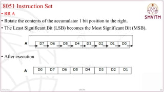
•RR A
• Rotate the contents of the accumulator 1 bit position to the right.
• The Least Significant Bit (LSB) becomes the Most Significant Bit (MSB).
• After execution
83
7/25/2022 18EC46
84.
8051 Instruction Set
•E.g.: RR A
• RRC A
• Rotate the contents of the accumulator and the carry bit 1 bit position to the right.
• The LSB becomes the carry bit and the carry bit becomes the MSB.
• Register addressing mode
• 1 byte
84
7/25/2022 18EC46
85.
8051 Instruction Set
•E.g.: RRC A
• Before execution: A= 7AH
• After execution: A= 3DH
85
7/25/2022 18EC46
86.
8051 Instruction Set
•SWAP A
• Exchange the lower and higher nibbles of the accumulator.
• Register addressing mode
• 1 byte
86
7/25/2022 18EC46
87.
8051 Instruction Set
•Boolean variable manipulation instructions:
• These instructions affect a single bit of a byte.
• The bit level Boolean logical opcodes operate on any bit addressable RAM or SFR
bit.
• The carry flag (CY) in the program status word (PSW) is the destination for most
of the opcodes.
• The various Boolean bit level operations are discussed below.
• Note that “b” is the bit- address (00h-7Fh) or bit addressable SFR
87
7/25/2022 18EC46
88.
8051 Instruction Set
•ANL C, b
• Logically AND the contents of the carry flag, C and the addressed bit, b and store
the result in carry flag C.
• Bit addressing mode, 2 byte
• E.g.: ANL C , P2.3
88
7/25/2022 18EC46
89.
8051 Architecture
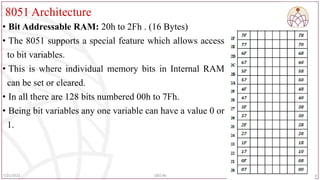
• BitAddressable RAM: 20h to 2Fh . (16 Bytes)
• The 8051 supports a special feature which allows access
to bit variables.
• This is where individual memory bits in Internal RAM
can be set or cleared.
• In all there are 128 bits numbered 00h to 7Fh.
• Being bit variables any one variable can have a value 0 or
1.
89
7/25/2022 18EC46
90.
8051 Instruction Set
•ANL C, /b
• Logically AND the contents of the carry flag, C and the complement of the
addressed bit, b and store the result in carry flag ,C.
• Bit addressing mode, 2 byte
• Example: ANL C, /05H
90
7/25/2022 18EC46
91.
8051 Instruction Set
•ORL C, b
• Logically OR the contents of the carry flag, C and the addressed bit, b and store
the result in carry flag ,C.
• Bit addressing mode, 2 byte
• Example: ORL C , P3.3
91
7/25/2022 18EC46
92.
8051 Instruction Set
•ORL C, /b
• Logically OR the contents of the carry flag, C and the complement of the
addressed bit, b and store the result in carry flag ,C.
• Bit addressing mode, 2 byte
• E.g.: ORL C, /05H
92
7/25/2022 18EC46
93.
8051 Instruction Set
•CPL C
• Complement the contents of the carry flag, C ,i.e. change 1 to 0 and vice versa.
• Bit inherent addressing mode
• 1 byte
• CPL b
• Complement the contents of the addressed bit, b ,i.e. change 1 to 0 and vice versa.
• Bit direct addressing mode
• 2 bytes
• Example: CPL P1.2
93
7/25/2022 18EC46
94.
8051 Instruction Set
•CLR C
• Clear the contents of the carry flag to 0.
• Bit inherent addressing mode
• 1 byte
• CLR b
• Clear the contents of the addressed bit, b to 0.
• Bit direct addressing mode
• 2 bytes
• E.g.: CLR P0.2 ; clear the contents of the bit 2 of Port0 (P0.2) to 0.
94
7/25/2022 18EC46
95.
8051 Instruction Set
•SETB C
• Set the contents of the carry flag to 1.
• Bit inherent addressing mode
• 1 byte
• Example: SETB C
• SETB b
• Set the contents of the addressed bit, b to 1.
• Bit direct addressing mode
• 2 bytes
• E.g.: SETB P1.5 ; set the contents of the bit 5 of Port1 (P1.5) to 1.
95
7/25/2022 18EC46
96.
8051 Instruction Set
•MOV C, b
• Copy the contents of the addressed bit(b), to the carry flag, C.
• Bit addressing mode
• 2 bytes
• E.g.: MOV C, P2.4 ; copy the contents of bit 4 of port 2 to the carry flag, C.
• MOV b, C
• Copy the contents of the carry flag, C to the addressed bit(b).
• Bit addressing mode
• 2 bytes
• E.g.: MOV P0.4, C; copy the contents of the carry flag, C to bit 4 of Port 0(P0.4).
96
7/25/2022 18EC46
97.
8051 Instruction Set
•Points to remember:
• No flags , other than the carry flag are affected unless the flag is an addressed bit .
• ANL C, /b and ORL C,/b do not alter the addressed bit b.
• JUMP and CALL Instructions
• The 8051 executes the program sequentially by fetching the instructions from the
memory.
• The contents of the PC are used as the memory address from where the instruction
is to be fetched.
• While fetching the instruction from the memory, the PC contents are automatically
incremented so that the PC always contains the memory address of the next
instruction to be fetched.
97
7/25/2022 18EC46
98.
8051 Instruction Set
•Thus, the microcontroller executes the instructions sequentially.
• This concept is demonstrated as shown in the adjacent diagram.
• The program is executed from top to bottom of the program
memory.
• The jump instructions are used to change this sequence of program
execution.
• To change this sequence of program execution, the contents of PC
must be altered.
• Therefore, any jump instruction primarily does only one
operation of changing the contents of PC.
98
7/25/2022 18EC46
99.
8051 Instruction Set
•As shown in the figure, any part of the
program or a set of instructions can be
omitted in the execution by using jump
instructions which makes the control of
program execution to be diverted to any part of
the program
• To realize the jump operation, we have to write
the JMP instruction in the program where
deviation from the normal sequence of program
execution is required.
99
7/25/2022 18EC46
8051 Instruction Set
•Unconditional SHORT JUMP instruction
• Syntax: SJMP rel_addr
• Here the rel_addr is an 8-bit signed number.
• When the above instruction is executed, the given 8-bit rel_addr is added to the
contents of PC (PC) (PC) +rel_addr
• Since the PC contents are changed, the microcontroller is said to perform the jump
operation.
• Since the relative address is added to the PC, the actual contents of PC after the
execution of the instruction depend on the present contents of the PC.
• Hence it is called relative mode of addressing.
101
7/25/2022 18EC46
102.
8051 Instruction Set
•Since the relative address is only 8-bit signed number, the range of the relative
address is -128 to +127.
• That is from the current location the microcontroller can jump by 127 locations in
the forward direction and 128 locations in the reverse direction.
• Therefore, the range of jump is very limited and hence it is called SHORT jump
operation.
• E.g.: SJMP 15H
102
7/25/2022 18EC46
103.
8051 Instruction Set
•ABSOLUTE JUMP OPERATION
• W.k.t. the program memory of 64KB is divided into 32 parts and each part is
called a PAGE.
• The size of the each page is = 2KB.
• The instruction that performs the jump operation within the same page is called
absolute jump operation.
• The various pages along with the page addresses are as shown in the following
figure.
103
7/25/2022 18EC46
104.
8051 Instruction Set
•The absolute jump operation performs the branch operation within the same page.
• For any page the address boundary is such that the most significant 5-bits of the address
will be the same and the least significant 11-bits of the address will change.
• Therefore, the absolute jump operation will alter only the least significant 11-bits of the
program counter PC.
104
7/25/2022 18EC46
105.
8051 Instruction Set
•E.g.: AJMP abs_addr
• The given 11-bits of address will be transferred to the PC and the most significant
5-bits will remain the same.
• E.g.: AJMP 5789H
105
7/25/2022 18EC46
106.
8051 Instruction Set
•LONG JUMP OPERATION
• This jump instruction is used to jump from any part of the memory to any other
part of the memory.
• That is, all the 16-bits of the PC are changed by the instruction.
• Ex: LJMP addr
• The jump operation is performed by loading the PC with the given address.
• Ex: LJMP 1235H
106
7/25/2022 18EC46
107.
8051 Instruction Set
•JMP @A+DPTR
• This instruction performs long jump operation by loading the PC with a 16-bit
address.
• The address is computed by adding the contents of A and DPTR.
107
7/25/2022 18EC46
108.
8051 Instruction Set
•CONDITIONAL JUMP INSTRUCTIONS
• These perform jump operation based on a user specified condition.
• Every conditional jump instruction specifies a condition.
• The operation of conditional instruction:
• Microcontroller checks the condition specified in the instruction.
• If the condition is true, then the microcontroller performs the jump operation by
adding the rel_addr given in the instruction to the program counter PC.
• (PC) (PC) +rel_addr
• If the condition is false, the PC contents are not modified and the microcontroller
will execute the next instruction in the sequence as usual
• The microcontroller will not perform the jump operation.
108
7/25/2022 18EC46
109.
8051 Instruction Set
•Conditional jump instructions based on bits (BIT JUMP)
• JC rel_addr
• JC instruction will branch to the address indicated by rel_addr if the Carry bit is
set.
• The jump operation is performed by adding the rel_addr to the contents of PC.
• (PC) (PC)+rel_addr
• If the Carry bit is not set program execution continues with the instruction
following the JC instruction.
• This is a short jump instruction.
• E.g.: JC 20H ; jump if carry =1
109
7/25/2022 18EC46
110.
8051 Instruction Set
•JNC rel_addr
• JNC instruction will branch to the address indicated by rel_addr if the Carry bit is
reset.
• The jump operation is performed by adding the rel_addr to the contents of PC.
• (PC) (PC)+rel_addr
• If the Carry bit is set program execution continues with the instruction following
the JNC instruction. This is a short jump instruction.
• E.g.: JNC 20H; jump if no carry(CY=0)
110
7/25/2022 18EC46
111.
8051 Instruction Set
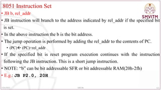
•JB b, rel_addr
• JB instruction will branch to the address indicated by rel_addr if the specified bit
is set.
• In the above instruction the b is the bit address.
• The jump operation is performed by adding the rel_addr to the contents of PC.
• (PC) (PC)+rel_addr
• If the specified bit is reset program execution continues with the instruction
following the JB instruction. This is a short jump instruction.
• NOTE: “b” can be bit addressable SFR or bit addressable RAM(20h-2fh)
• E.g.: JB P2.0, 20H
111
7/25/2022 18EC46
112.
8051 Instruction Set
•JNB b, rel_addr
• JNB instruction will branch to the address indicated by rel_addr if the specified bit
is reset.
• In the above instruction the b is the bit address.
• The jump operation is performed by adding the rel_addr to the contents of PC.
• (PC) (PC)+rel_addr
• If the specified bit is set program execution continues with the instruction
following the JNB instruction. This is a short jump instruction.
• E.g.: JNB P2.0, 20H
112
7/25/2022 18EC46
113.
8051 Instruction Set
•JBC b, rel_addr
• This will branch to the address indicated by rel_addr if the specified bit is set.
• After performing the jump operation, the specified bit is reset.
• In the above instruction the b is the bit address.
• The jump operation is performed by adding the rel_addr to the contents of PC.
• (PC) (PC)+rel_addr
• If the specified bit is reset program execution continues with the instruction
following the JBC instruction. This is a short jump instruction.
• E.g.: JBC P2.0, 20H
113
7/25/2022 18EC46
114.
8051 Instruction Set
•CONDITIONAL JUMP INSTRUCTIONS BASED ON ACCUMULATOR
CONTENTS (BYTE JUMP)
• JZ rel_addr
• This will branch to the address indicated by rel_addr if the accumulator contents
are zero.
• The jump operation is performed by adding the rel_addr to the contents of PC.
• If the accumulator contents are not zero, program execution continues with the
next instruction following the JZ instruction. This is a short jump instruction.
• E.g.: JZ 20H
114
7/25/2022 18EC46
115.
8051 Instruction Set
•JNZ rel_addr
• This will branch to the address indicated by rel_addr if the accumulator contents
are not zero.
• The jump operation is performed by adding the rel_addr to the contents of PC.
• If the accumulator contents are zero, program execution continues with the
instruction following the JNZ instruction. This is a short jump instruction.
• E.g.: JNZ 20H
115
7/25/2022 18EC46
116.
8051 Instruction Set
•Logical Instructions- Compare Instruction
• CJNE destination, source, Label
• The actions of comparing and jumping are combined into a single instruction
called CJNE (compare and jump if not equal)
• The CJNE instruction compares two operands, and jumps if they are not equal
• The destination operand can be in the accumulator or in one of the Rn registers
• The source operand can be in a register, in memory, or immediate
• The operands remain unchanged
• It changes the CY flag to indicate if the destination operand is larger or smaller
116
7/25/2022 18EC46
117.
8051 Instruction Set
•Note: In the CJNE instruction, any Rn register can be compared with an
immediate value
• There is no need for register A to be involved
• The comparison is done similar to subtraction instruction, except that the operands
remain unchanged
• Flags are changed according to the execution of the SUBB instruction
• Write a program to read the temperature and test it for the value 75.
• According to the test results, place the temperature value into the registers
indicated by the following.
• If T = 75 then A = 75
• If T < 75 then R1 = T
• If T > 75 then R2 = T
117
7/25/2022 18EC46
118.
8051 Instruction Set
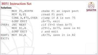
Solution:
MOVP1,#0FFH ;make P1 an input port
MOV A,P1 ;read P1 port
CJNE A,#75,OVER ;jump if A is not 75
SJMP EXIT ;A=75, exit
OVER: JNC NEXT ;if CY=0 then A>75
MOV R1,A ;CY=1, A<75, save in R1
SJMP EXIT ; and exit
NEXT: MOV R2,A ;A>75, save it in R2
EXIT:
118
7/25/2022 18EC46
119.
8051 Instruction Set
•Conditional jump instruction based on decrement operation
• General form : DJNZ operand , rel_addr
• The contents of the specified operand are decremented by 1 and the result is
placed in the same operand.
• E.g.1 : DJNZ R7, 50H
• (operand) (operand)-1
• After decrementing the contents of the operand the microcontroller performs the
jump operation if the contents of the operand are not zero.
119
7/25/2022 18EC46
120.
8051 Instruction Set
•E.g.2: DJNZ 35H, 50H
• In this, 35h is the address of the RAM location whose contents are decremented.
• That is, the RAM location 35H is the operand of the instruction.
120
7/25/2022 18EC46
121.
8051 Instruction Set
•; Write a program to
• (a) load the accumulator with the value 55H, and
• (b) complement the ACC 700 times
• MOV A,#55H ;A=55H
• MOV R3,#10 ;R3=10, outer loop count
• NEXT: MOV R2,#70 ;R2=70, inner loop count
• AGAIN: CPL A ;complement A register
• DJNZ R2,AGAIN ;repeat it 70 times
• DJNZ R3,NEXT
121
7/25/2022 18EC46
122.
8051 Instruction Set
•Find the sum of the values 79H, F5H, E2H. Put the sum in registers R0 (low byte) and
R5 (high byte).
• MOV A,#0 ;A=0
• MOV R5,A ;clear R5
• ADD A,#79H ;A=0+79H=79H
• JNC N_1 ;if CY=0, add next number
• INC R5 ;if CY=1, increment R5
• N_1: ADD A,#0F5H ;A=79+F5=6E and CY=1
• JNC N_2 ;jump if CY=0
• INC R5 ;if CY=1,increment R5 (R5=1)
• N_2: ADD A,#0E2H ;A=6E+E2=50 and CY=1
• JNC OVER ;jump if CY=0
• INC R5 ;if CY=1, increment 5
• OVER: MOV R0,A ;now R0=50H, and R5=02 122
7/25/2022 18EC46
123.
8051 Instruction Set
•Other forms of CJNE instruction
• CJNE A, addr, rel_addr
• CJNE A, #D8, rel_addr
• CJNE @RP, #D8, rel_addr
• CJNE Rn, A, rel_addr
123
7/25/2022 18EC46
124.
8051 Instruction Set
•Calls and Subroutines
• A subroutine is a group of instructions that performs a specified task.
• It is written independently of a main program and can be called multiple times to
perform that task whenever needed by the main program or by another subroutine.
• Common practice when writing a large program is to divide the total task into
small independent tasks or modules that are written independently as subroutines
and brought together to build a large program.
• In terms of efficiency, subroutines save memory space.
• E.g.: if we need a 100ms delay five times in the main program, we can write a
100ms delay subroutine once and call it five times.
124
7/25/2022 18EC46
8051 Instruction Set
•Absolute CALL:
• Syntax: ACALL abs_addr
• This call instruction calls a subroutine which is in the same page as that of the
calling program.
• The given abs_addr is the 11-bit address of the subroutine.
• The instruction is executed as follows.
• The content of the program counter which is the return address of the main
program is preserved on the stack by performing PUSH operation.
• (SP) (SP)+1
• ((SP)) (PCL)
• (SP) (SP)+1
• ((SP)) (PCH)
126
7/25/2022 18EC46
127.
8051 Instruction Set
•After preserving the contents of the PC, the 16-bit address is transferred to the PC.
• (PC) abs_addr
• E.g.:ACALL 0768H
127
7/25/2022 18EC46
128.
8051 Instruction Set
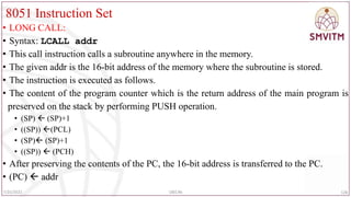
•LONG CALL:
• Syntax: LCALL addr
• This call instruction calls a subroutine anywhere in the memory.
• The given addr is the 16-bit address of the memory where the subroutine is stored.
• The instruction is executed as follows.
• The content of the program counter which is the return address of the main program is
preserved on the stack by performing PUSH operation.
• (SP) (SP)+1
• ((SP)) (PCL)
• (SP) (SP)+1
• ((SP)) (PCH)
• After preserving the contents of the PC, the 16-bit address is transferred to the PC.
• (PC) addr
128
7/25/2022 18EC46
8051 Instruction Set
•Returning From the Subroutine:
• At the end of the subroutine, the control of program execution is transferred to the
main program.
• For this RET instruction is used.
• This instruction will not specify the address of the main program to which the
control must be transferred.
• Syntax: RET
• The instruction is executed as follows:
• The address of the main program to which the control must be transferred is called
“return address”.
• This return address must be present in the stack memory.
130
7/25/2022 18EC46
131.
8051 Instruction Set
•The contents of the top of the stack memory are transferred to the program counter
PC.
• With this the microcontroller automatically jumps to the main program.
• (PCH) ((SP))
• (SP) (SP)-1
• (PCL) ((SP))
• (SP)(SP)-1
• E.g.: RET
131
7/25/2022 18EC46
132.
8051 Instruction Set
Writean ALP to add two bytes from RAM location 30H and 31H and store the
result in RAM address 40H carry in 41H.
ORG 00H
MOV R1,00H; R1=00H, space to store the carry
MOV A, 30H;
ADD A, 31H; two bytes are added and result is stored in A
JNC DOWN; if carry not generated jump to lable DOWN
INC R1; if carry generated, increment R1
DOWN:MOV 40H,A; store the final result in RAM address 40h
MOV 41H,R1; store the carry in RAM address 41h
END; end the program
132
7/25/2022 18EC46
133.
8051 Instruction Set
ORG0000H;
MOV R0,#30H; R0=30H
MOV R1,#40H; R1=40H
MOV B,#00H; B=00H
MOV A,@R0; A=first data byte from address 30H
INC R0; R0=31H
ADD A,@R0; ADD TWO DATA BYTES; A=A+(31H)
JNC L1; if carry not generated jump to specified lable (L1)
INC B; if carry generated, increment register content B=01
L1: MOV @R1,B; store the carry into RAM address 40H
INC R1; increment R1=41H
MOV @R1,A; store the final addition result at RAM address 41H
END
133
7/25/2022 18EC46
Another way
134.
8051 Instruction Set
•ALP to add ten 8 bit numbers:
ORG 0000H;
MOV R0,#30H ;
MOV R1,#50H ; result
MOV R2,#09H ; count
MOV B,#00H
CLR C
MOV A,@R0
UP: INC R0
ADD A,@R0
JNC L1
INC B
L1: DJNZ R2,UP
MOV @R1,B
INC R1
MOV @R1,A
END
134
7/25/2022 18EC46
135.
8051 Instruction Set
•ALP to subtract two bytes which is present RAM location 20h and 30h and store
the result in RAM location 44h , borrow 45h
• ORG 0000h
• MOV R1,#00H
• MOV A, 20H
• SUBB A, 30H
• JNC DOWN
• INC R1
• DOWN: MOV 44H,A
• MOV 45H, R1
• END
135
7/25/2022 18EC46
20H=05 30H=02H
RESULT =03H B=00H
136.
8051 Instruction Set
•Assume that 5 BCD data items are stored in RAM locations starting at 40H, as shown
below. Write a program to find the sum of all the numbers. The result must be in BCD.
40=(71); 41=(11); 42=(65); 43=(59); 44=(37)
• MOV R0,#40H ;Load pointer
• MOV R2,#5 ;Load counter
• CLR A ;A=0
• MOV R7,A ;Clear R7
• AGAIN: ADD A,@R0 ;add the byte pointer ;to by R0
• DA A ;adjust for BCD
• JNC NEXT ;if CY=0 don’t accumulate carry
• INC R7 ;keep track of carries
• NEXT: INC R0 ;increment pointer
• DJNZ R2,AGAIN ;repeat until R2 is 0
136
7/25/2022 18EC46
137.
8051 Instruction Set
•Find the sum of the values 79H, F5H, E2H. Put the sum in registers R0 (low byte) and
R5 (high byte).
• MOV A,#0 ;A=0
• MOV R5,A ;clear R5
• ADD A,#79H ;A=0+79H=79H
• JNC N_1 ;if CY=0, add next number
• INC R5 ;if CY=1, increment R5
• N_1: ADD A,#0F5H ;A=79+F5=6E and CY=1
• JNC N_2 ;jump if CY=0
• INC R5 ;if CY=1,increment R5 (R5=1)
• N_2: ADD A,#0E2H ;A=6E+E2=50 and CY=1
• JNC OVER ;jump if CY=0
• INC R5 ;if CY=1, increment 5
• OVER: MOV R0,A ;now R0=50H, and R5=02 137
7/25/2022 18EC46
138.
8051 Instruction Set
•Write a program to get convert the hex data in the stored in 35H to
decimal. Save it in R7, R6 and R5.
• Solution:
• MOV A, 35H ;read data
• MOV B, #10 ;B=0A hex
• DIV AB ;divide by 10
• MOV R7, B ;save lower digit
• MOV B, #10
• DIV AB ;divide by 10 once more
• MOV R6, B ;save the next digit
• MOV R5, A ;save the last digit
138
7/25/2022 18EC46
139.
8051 Instruction Set
•Write a program to convert packed BCD to two ASCII numbers and place them in R2 and R6.
• MOV A,#29H ;A=29H, packed BCD
• MOV R2,A ;keep a copy of BCD data
• ANL A,#0FH ;mask the upper nibble (A=09)
• ORL A,#30H ;make it an ASCII, A=39H(‘9’)
• MOV R6,A ;save it
• MOV A,R2 ;A=29H, get the original data
• ANL A,#0F0H ;mask the lower nibble
• RR A ;rotate right
• RR A ;rotate right
• RR A ;rotate right
• RR A ;rotate right
• ORL A,#30H ;A=32H, ASCII char. ’2’
• MOV R2,A ;save ASCII char in R2
139
7/25/2022 18EC46
140.
8051 Instruction Set
ORG0000H
MOV 40H,#05H
MOV 41H,#55H
MOV 42H,#06H
MOV 43H,#1AH
MOV 44H,#09H
MOV R0,#40H
MOV R5,#05H
MOV B,R5
CLR A
Loop: ADD A,@R0
INC R0
DJNZ R5,Loop
DIV A B
MOV 55H,A
END
140
7/25/2022 18EC46
Write a program to find the average of five 8 bit numbers. Store the result in 55H.
(Assume that after adding five 8 bit numbers, the result is 8 bit only).
141.
8051 Instruction Set
•Write a program to count the number of and 0's of 8 bit data stored in
location 6000H.
• ORG 0000 ; Set program counter 00008
• MOV DPTR, #6000h ; Copy address 6000H to DPTR
• MOVX A, @DPTR ; Copy number to A
• MOV R0,#08 ; Copy 08 in R0
• MOV R2,#00 ; Copy 00 in R2
• MOV R3,#00 ; Copy 00 in R3
• CLR C ; Clear carry flag
• BACK: RLC A ; Rotate A through carry flag
• JNC NEXT ; If CF=0 jump to NEXT
• INC R2 ; If CF = 1, increment R2
• AJMP NEXT2
• NEXT: INC R3 ; If CF = 1, increment R3
• NEXT2: DJNZ R0,BACK ; Repeat until R0 is zero
141
7/25/2022 18EC46
142.
8051 Instruction Set
•Write a program to multiply two 8 bit numbers stored at locations 70H and 71H
and store the result at memory locations 52H and 53H. Assume that the least
significant byte of the result is stored in low address.
• ORG 0000H ; Set program counter 00 OH
• MOV A, 70H ; Load the contents of memory location 70h into A
• MOV B, 71H ; Load the contents of memory location 71H into B
• MUL A B ; Perform multiplication
• MOV 52H,A ; Save the least significant byte of the result in location 52H
• MOV 53H,B ; Save the most significant byte of the result in location 53
• END
142
7/25/2022 18EC46
143.
8051 Instruction Set
•Write a program to compute 1 + 2 + 3 + N (say N=15) and save the sum
at70H
• ORG 0000H ; Set program counter 0000H
• N EQU 15
• MOV R0,#00 ; Clear R0
• CLR A ; Clear A
• again: INC R0 ; Increment R0
• ADD A, R0 ; Add the contents of R0 with A
• CJNE R0,#N,again ; Loop until counter, R0, N
• MOV 70H,A ; Save the result in location 70H
• END 143
7/25/2022 18EC46
144.
8051 Instruction Set
•Program to find Find a Factorial of N
• ORG 0000H
• MOV R0,#5 ;Number N
• MOV A,R0
• ACALL FACT ;11bit function call
• fact: DEC R0
• CJNE R0,#01,rel ;value of R0 is compared with 1
• SJMP stop ;if R0=1, stop execution
• rel: MOV B,R0
• MUL AB
• ACALL FACT ;calling back the same function
• stop: END
144
7/25/2022 18EC46
145.
8051 Instruction Set
•Write a program to add two 16 bit numbers stored at locations 51H-52H and 55H-56H and store
the result in locations 40H, 41H and 42H. Assume that the least significant byte of data and the
result is stored in low address and the most significant byte of data or the result is stored in high
address.
• ORG 0000H ; Set program counter 0000H
• MOV A,51H ; Load the contents of memory location 51H into A
• ADD A,55H ; Add the contents of 55H with contents of A
• MOV 40H,A ; Save the LS byte of the result in location 40H
• MOV A,52H ; Load the contents of 52H into A
• ADDC A,56H ; Add the contents of 56H and CY flag with A
• MOV 41H,A ; Save the second byte of the result in 41H
• MOV A,#00 ; Load 00H into A
• ADDC A,#00 ; Add the immediate data 00H and CY to A
• MOV 42H,A ; Save the MS byte of the result in location 42H
• END
145
7/25/2022 18EC46