Download as PDF, PPTX


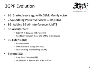
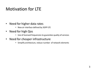
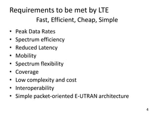
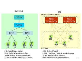
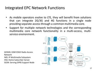
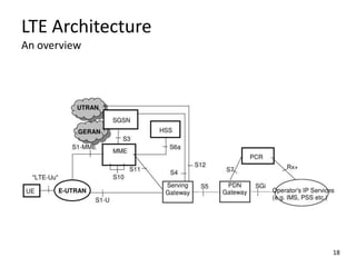
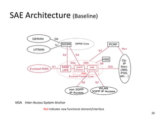


The document discusses the evolution of 3G networks to 4G LTE networks. It describes the key aspects of LTE including the LTE architecture, air interface technologies like OFDMA and SC-FDMA, and the Evolved Packet Core. The goals of LTE were to provide higher data rates, improve spectrum efficiency, reduce latency and simplify the network architecture. LTE adopted an all-IP flat architecture with reduced network elements in the core to help lower costs and complexity.


