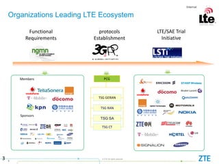
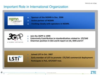
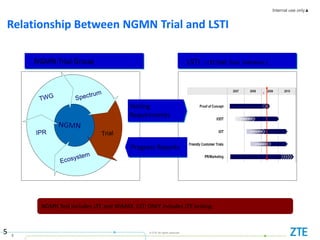
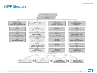
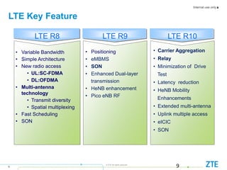
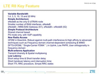
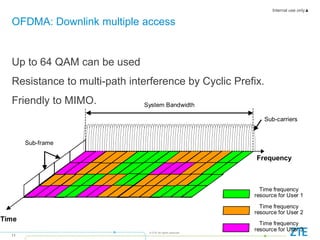
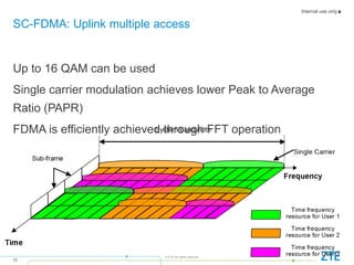
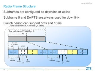
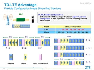
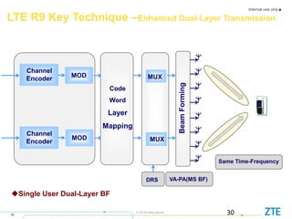
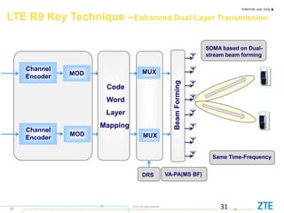
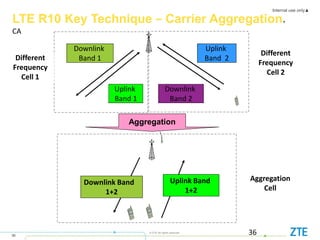
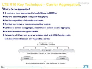
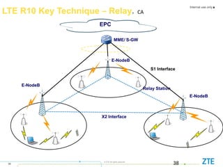
ZTE Corporation
2015/11/5
LTE Key Technologies
Content
 LTE Organization
 LTE Basic Technologies
 Key Technology of R9
 Key Technology of R10
Internal use only▲
3
© ZTE All rights reserved
Organizations Leading LTE Ecosystem
3
Functional
Requirements
protocols
Establishment
LTE/SAE Trial
Initiative
TSG RAN
TSG SA
TSG CT
PCG
TSG GERAN
Members
Sponsors
Internal use only▲
4
© ZTE All rights reserved
Important Role in International Organization
4
 Sponsor of the NGMN in Dec. 2006
 Active partner of NGMN
 Working closely with operators in NGMN.
 Joined LSTI in Oct. 2007
 Early member of LSTI to promote LTE/SAE commercial deployment
 Participate in PoC, IOT/IODT trial.
 Join the 3GPP in 1999
 Extensively Contribution to standardization related to LTE/SAE
 Chairmen position in SA5 and 8 report on SA, RAN and CT
Internal use only▲
5
© ZTE All rights reserved
NGMN Trial Group LSTI (LTE/SAE Trial Initiative )
Progress Reports
NGMN Test includes LTE and WiMAX. LSTI ONLY includes LTE testing.
Relationship Between NGMN Trial and LSTI
Testing
Requirements
5
Internal use only▲
6
© ZTE All rights reserved
Functional Areas LSTI
6
Internal use only▲
7
© ZTE All rights reserved
3GPP Structure
Content
 LTE Organization
 LTE Basic Technologies
 Key Technology of R9
 Key Technology of R10
Internal use only▲
9
© ZTE All rights reserved
LTE Key Feature
9
LTE R8 LTE R9 LTE R10
• Variable Bandwidth
• Simple Architecture
• New radio access
• UL:SC-FDMA
• DL:OFDMA
• Multi-antenna
technology
• Transmit diversity
• Spatial multiplexing
• Fast Scheduling
• SON
• Positioning
• eMBMS
• SON
• Enhanced Dual-layer
transmission
• HeNB enhancement
• Pico eNB RF
• Carrier Aggregation
• Relay
• Minimization of Drive
Test
• Latency reduction
• HeNB Mobility
Enhancements
• Extended multi-antenna
• Uplink multiple access
• eICIC
• SON
Internal use only▲
10
© ZTE All rights reserved
10
LTE R8 Key Feature
Variable Bandwidth
1.4, 3, 5, 10, 15 and 20 MHz
Simple Architecture
eNodeB as the only E-UTRAN node
Smaller number of RAN interfaces, eNodeB
eNodeB « MME/SAE-Gateway (S1), eNodeB « eNodeB (X2)
Simple Protocol Architecture
Shared channel based
PS mode only, with VoIP capability
New Radio Access
OFDM in Downlink, Robust against multi-path interference & High affinity to advanced
techniques such as Frequency domain channel-dependent scheduling & MIMO
DFTS-OFDM(“Single-Carrier FDMA”) in Uplink, Low PAPR, User orthogonality in
frequency domain
Multi-antenna Application
Transmit diversity & Spatial multiplexing
Low Latency
Short setup time & Short transfer delay
Short handover latency and interruption time;
Short TTI, RRC procedure, Simple RRC states
Internal use only▲
11
© ZTE All rights reserved
Up to 64 QAM can be used
Resistance to multi-path interference by Cyclic Prefix.
Friendly to MIMO.
OFDMA: Downlink multiple access
Sub-carriers
Sub-frame
Frequency
Time
Time frequency
resource for User 1
Time frequency
resource for User 2
Time frequency
resource for User 3
System Bandwidth
Internal use only▲
12
© ZTE All rights reserved
Up to 16 QAM can be used
Single carrier modulation achieves lower Peak to Average
Ratio (PAPR)
FDMA is efficiently achieved through FFT operation
SC-FDMA: Uplink multiple access
Internal use only▲
13
© ZTE All rights reserved
Subframes are configured as downlink or uplink
Subframe 0 and DwPTS are always used for downlink
Switch period can support 5ms and 10ms
Radio Frame Structure
One
subframe
Subframe #5
DwPTS
GP
UpPTS
… Subframe #9
One half-frame 153600 TS = 5
ms
One
subframe
Subframe #0
DwPTS
GP
UpPTS
30720TS
… Subframe #4
One slot
Tslot=15360TS
One radio frame Tf = 307200 Ts = 10 ms
Internal use only▲
14
© ZTE All rights reserved
TDD
D U U U D D D D D
DL/UL flexible configuration:
Different with FDD technology, TD-LTE can adjust DL/UL time
configuration to meet asymmetric services according different
service types.
Period DL/UL configuration
5 ms 1DL:3UL, 2DL:2UL, 3DL:1UL
10 ms 6DL:3UL, 7DL:2UL, 8DL:1UL, 3DL:5UL
10ms
6 : 3
7 : 2
8 : 1
5ms 5ms
3 : 5
Downlink Uplink DwPTS+GP+UpPTS
5ms
1 : 3
5ms
2 : 2
5ms
3 : 1
TD-LTE Advantage
Flexible Configuration Meets Diversified Services
Internal use only▲
15
© ZTE All rights reserved
3GPP Specification(36.213) provides the tables showing the
mapping between MCS (Modulation and Coding Scheme)
index and TBS (Transport Block Size)
TBS indicates the throughput.
Tables in the Specification 36.213
– Table(7.1.7.1-1): DL mapping between MCS index with TBS index.
– Table(8.6.1-1): UL mapping between MCS index with TBS index
– Table(7.1.7.2.1-1): mapping between TBS index + NPRB with TBS.
TD-LTE Peak Throughput Calculation
Internal use only▲
16
© ZTE All rights reserved
Step 1: ITBS from Table 7.1.7.1 of 3GPP 36.213.
Step 2: TBsize from Table 7.1.7.2.1 -1 of 3GPP 36.213
Step 3: Calculation formula:
Throughput =
((Num of D)*(TBSize of D)+ (Num of S)*(TBSize of S))/ (Time of TTI)
– Number of D : Downlink subframe number
– TBsize of D : TBSize of downlink from 3GPP TBS table(7.1.7.2.1-1)
– Num of S : Number of special subframe, special s can be used for DL data transmission.
– TBSize of S : TBSize of 3GPP TBS table(7.1.7.2.1-1),
3GPP set the NPRB of S = NPRB of D * 0.75, then use the NPRB of
S to get TBSize from table (7.1.7.2.1.-1)
– Time of TTI = 10ms
Throughput Calculation for DL
Internal use only▲
17
© ZTE All rights reserved
Transport
Block
Concept of TB (Transport block)
TBSize: Size of TB(bit).
Transport block (TB): is a group of resource blocks with a common modulation/coding.
The physical resource is a transport block, which corresponds to the data carried in a period of
time .
Internal use only▲
18
© ZTE All rights reserved
DL Step 1: Get ITBS
Qm
2 QPSK
4 16QAM
6 64QAM
7.1.7.1-1 table Modulation and TBS Index Table for PDSCH(3GPP 36.213)
Set IMCS = 28
ITBS = 26
Internal use only▲
19
© ZTE All rights reserved
DL Step 2: Get TBSize
Table 7.1.7.2.1-1: Transport block size table
• Itbs = 26
• NPRB = 100, TBSize of D = 75376 bits
• For Special subframe NPRB’ = 100 * 0.75 = 75, TBSize of S = 55056 bits
Internal use only▲
20
© ZTE All rights reserved
Throughput =
((Num of D)*(TBSize of D)+ (Num of S)*(TBSize of S))/ (Time of TTI)
– Timeslot Configuration : 2 ,2DL:2UL,
4 DL subframe per frame(10ms).
– Num of D = 4
– TBSize of D = 75376 bits
– Num of S = 2
– TBSize of S = 55056 bits
Throughput = (75736 * 4 + 55056*2)/10ms = 41.31 Mbps
For 2X2 MIMO, We assume peak throughput = 41.31 * 2 = 82.62Mbps
DL Step 3: Calculation
Internal use only▲
21
© ZTE All rights reserved
Step 1: ITBS from Table (8.6.1-1)
Step 2: TBsize from Table 7.1.7.2.1 -1
Step 3: Calculation formula:
Throughput = ((Num of U)*(TBSize of U)/ (Time of TTI))
– Num of U : Number of UL subframe
– TBsize of U: TBSize from table 7.1.7.2.1-1 of UL subframe
– Time of TTI : 10ms
Throughput Calculation for UL
Internal use only▲
22
© ZTE All rights reserved
Step 1: Get ITBS
Set IMCS = 17
ITBS = 16
Internal use only▲
23
© ZTE All rights reserved
Step 2: Get TBSize
Set ITBS = 16, NPRB = 100
TBSize = 32856 bits
Internal use only▲
24
© ZTE All rights reserved
Throughput = ((Num of U)*(TBSize of U)/ 10ms)
Timeslot Configuration : 2
2DL:2UL,
4 DL sub frame per frame(10ms).
Num of U = 4
TBSize of U = 32856
Throughput = 4 * 32856 / 10ms = 13.142Mbps
Step 3: Calculation
Internal use only▲
25
© ZTE All rights reserved
Basic antenna configuration: 2*2 downlink, 1*2 uplink
Maximum antenna configuration: 4*4
Basic Concept of MIMO
 Improve spectrum efficiency based on space and time
processing technology
 Diversity: reduce the interference caused by channel
fading
 Spatial Multiplexing: gain the multiplied data rates
 Beamforming: weight the Tx vector to form the
directional beam
Internal use only▲
26
© ZTE All rights reserved
RX
Data
Encode
Encode
Channel
Interleave
Channel
Interleave
Modulator
QPSK
16QAM
Modulator
QPSK
16QAM
Detector
Detector
MUX
Data
v12
v21
v11
v22
TX
DeMUX
Space multiplexing & space diversity leads to higher bit rate.
MIMO Principle
Content
 LTE Organization
 LTE Basic Technologies
 Key Technology of R9
 Key Technology of R10
Internal use only▲
28
© ZTE All rights reserved
Functions, Features and Objective
Functions Features Objective
2G/3G LTE
 SON: avoid manual
intervention
SON-
enable
SON
Self-
maintenance
Self-
configuration
Self-
optimization
Self-
healing
SON
Enable
SON
Internal use only▲
29
© ZTE All rights reserved
Self-configuration and Self-optimization
Procedures
eNB power on
(or cable
connected)
(A) Basic Setup
(B) Initial Radio
Configuration
(C)Optimization
/Adaptation
configuration of IP address
and detection of OAM
authentication of eNB/NW
association to aGW
downloading of eNB
software (and operational
parameters)
coverage/capacity related
parameter configuration
neighbour list configuration
neighbour list optimisation
coverage and capacity
control
Self-Configuration
(pre-operational
state)
Self-Optimisation
(operational state)
Internal use only▲
30
© ZTE All rights reserved
30
LTE R9 Key Technique –Enhanced Dual-Layer Transmission
Single User Dual-Layer BF
MOD
Channel
Encoder
Channel
Encoder
MOD
Code
Word
Layer
Mapping
MUX
MUX
Beam
Forming
VA-PA(MS BF)
Same Time-Frequency
DRS
Internal use only▲
31
© ZTE All rights reserved
31
LTE R9 Key Technique –Enhanced Dual-Layer Transmission
MOD
Channel
Encoder
Channel
Encoder
MOD
Code
Word
Layer
Mapping
MUX
MUX
Beam
Forming
VA-PA(MS BF)
Same Time-Frequency
DRS
SDMA based on Dual-
stream beam forming
Internal use only▲
32
© ZTE All rights reserved
LTE R9 Key Technique –Enhanced Dual-Layer Transmission
32
 Beam Forming (BF) is helping to reach high system capacity and large coverage;
 BF is beneficial for increasing cell throughput and especially essential to users
at cell edge
 LTE Rel-8 already supports single-layer BF based on user-specific
Reference Symbols(RS);
 Multi-layer BF is proposed for LTE Rel-9.
Radio Link Enhancement Techniques were added for LTE.
Support single user dual-layer BF using UE specific RS for both LTE-TDD and FDD;
Design of UE specific demodulation reference signals and mapping of physical data
channel to resource elements aims for forward compatibility with LTE-A Demodulation RS;
Principles exploiting channel reciprocity were considered in the feedback design where
applicable.
Background for Enhanced Dual-Layer Transmission
Internal use only▲
33
© ZTE All rights reserved
33
LTE R9 Key Technique –Architecture with Deployed HeNB GW
E-UTRAN
MME / S-GW MME / S-GW
HeNB GW
X2
X2
X2
S1
S1
S1
S1
S1
S1
S1
S1
S1
HeNB HeNB
HeNB
eNB eNB
eNB
Internal use only▲
34
© ZTE All rights reserved
LTE R9 Key Technique – HeNB & HeNB GW
34
 The HeNB hosts the same functions as an eNB.
 One HeNB serves only one cell.
 The S1 interface between the HeNB and the EPC to scale to
support a large number of HeNBs.
 The S1 interface between the HeNB and the EPC is the
same whether the HeNB is connected to the EPC via a
HeNB GW or not.
 This version of the specification does not support X2
connectivity of HeNBs.
 The HeNB GW serves as a concentrator for the C-Plane,
specifically the S1-MME interface.
Content
 LTE Organization
 LTE Basic Technologies
 Key Technology of R9
 Key Technology of R10
Internal use only▲
36
© ZTE All rights reserved 36
Uplink
Band 1
Uplink
Band 2
Aggregation
Different
Frequency
Cell 1
Downlink
Band 1
Downlink
Band 2
LTE R10 Key Technique – Carrier Aggregation,
CA
Different
Frequency
Cell 2
Uplink Band
1+2
Aggregation
Cell
Downlink Band
1+2
Internal use only▲
37
© ZTE All rights reserved
37
LTE R10 Key Technique – Carrier Aggregation,
CA
What is Carrier Aggregation?
 2 carriers or more aggregated, the bandwidth up to 100MHz;
 Improve peak throughput and system throughput;
To solve the problem of discontinuous carrier;
Terminal can receive or transmission multiple carriers;
Continuous carriers can aggregate, discontinuous carriers can also aggregate;
Each carrier maximum supports100RBs;
Each carrier of UE can only see a transmission block and HARQ function entity;
Each transmission block can only mapped to a carrier.
Internal use only▲
38
© ZTE All rights reserved
38
LTE R10 Key Technique – Relay,CA
EPC
E-NodeB
Relay Station
MME/ S-GW
X2 Interface
S1 Interface
E-NodeB
E-NodeB
Internal use only▲
39
© ZTE All rights reserved
LTE R10 Key Technique – Relay
39
1 Why Introduce Relay?
 Group Mobility
Reduce handover interrupt time, increase throughput
 Provide Temporary Coverage
Avoid a large number cable deployment, lower CAPEX & OPEX
 Improve Cell Edge Throughput
Improve the reception quality effectively of cell edge users
 New Area Coverage
Improve spectrum efficiency with Introducing Relay Station in city region
or hot spots
Thank You
40

Lte key technologies

  • 1.
  • 2.
    Content  LTE Organization LTE Basic Technologies  Key Technology of R9  Key Technology of R10
  • 3.
    Internal use only▲ 3 ©ZTE All rights reserved Organizations Leading LTE Ecosystem 3 Functional Requirements protocols Establishment LTE/SAE Trial Initiative TSG RAN TSG SA TSG CT PCG TSG GERAN Members Sponsors
  • 4.
    Internal use only▲ 4 ©ZTE All rights reserved Important Role in International Organization 4  Sponsor of the NGMN in Dec. 2006  Active partner of NGMN  Working closely with operators in NGMN.  Joined LSTI in Oct. 2007  Early member of LSTI to promote LTE/SAE commercial deployment  Participate in PoC, IOT/IODT trial.  Join the 3GPP in 1999  Extensively Contribution to standardization related to LTE/SAE  Chairmen position in SA5 and 8 report on SA, RAN and CT
  • 5.
    Internal use only▲ 5 ©ZTE All rights reserved NGMN Trial Group LSTI (LTE/SAE Trial Initiative ) Progress Reports NGMN Test includes LTE and WiMAX. LSTI ONLY includes LTE testing. Relationship Between NGMN Trial and LSTI Testing Requirements 5
  • 6.
    Internal use only▲ 6 ©ZTE All rights reserved Functional Areas LSTI 6
  • 7.
    Internal use only▲ 7 ©ZTE All rights reserved 3GPP Structure
  • 8.
    Content  LTE Organization LTE Basic Technologies  Key Technology of R9  Key Technology of R10
  • 9.
    Internal use only▲ 9 ©ZTE All rights reserved LTE Key Feature 9 LTE R8 LTE R9 LTE R10 • Variable Bandwidth • Simple Architecture • New radio access • UL:SC-FDMA • DL:OFDMA • Multi-antenna technology • Transmit diversity • Spatial multiplexing • Fast Scheduling • SON • Positioning • eMBMS • SON • Enhanced Dual-layer transmission • HeNB enhancement • Pico eNB RF • Carrier Aggregation • Relay • Minimization of Drive Test • Latency reduction • HeNB Mobility Enhancements • Extended multi-antenna • Uplink multiple access • eICIC • SON
  • 10.
    Internal use only▲ 10 ©ZTE All rights reserved 10 LTE R8 Key Feature Variable Bandwidth 1.4, 3, 5, 10, 15 and 20 MHz Simple Architecture eNodeB as the only E-UTRAN node Smaller number of RAN interfaces, eNodeB eNodeB « MME/SAE-Gateway (S1), eNodeB « eNodeB (X2) Simple Protocol Architecture Shared channel based PS mode only, with VoIP capability New Radio Access OFDM in Downlink, Robust against multi-path interference & High affinity to advanced techniques such as Frequency domain channel-dependent scheduling & MIMO DFTS-OFDM(“Single-Carrier FDMA”) in Uplink, Low PAPR, User orthogonality in frequency domain Multi-antenna Application Transmit diversity & Spatial multiplexing Low Latency Short setup time & Short transfer delay Short handover latency and interruption time; Short TTI, RRC procedure, Simple RRC states
  • 11.
    Internal use only▲ 11 ©ZTE All rights reserved Up to 64 QAM can be used Resistance to multi-path interference by Cyclic Prefix. Friendly to MIMO. OFDMA: Downlink multiple access Sub-carriers Sub-frame Frequency Time Time frequency resource for User 1 Time frequency resource for User 2 Time frequency resource for User 3 System Bandwidth
  • 12.
    Internal use only▲ 12 ©ZTE All rights reserved Up to 16 QAM can be used Single carrier modulation achieves lower Peak to Average Ratio (PAPR) FDMA is efficiently achieved through FFT operation SC-FDMA: Uplink multiple access
  • 13.
    Internal use only▲ 13 ©ZTE All rights reserved Subframes are configured as downlink or uplink Subframe 0 and DwPTS are always used for downlink Switch period can support 5ms and 10ms Radio Frame Structure One subframe Subframe #5 DwPTS GP UpPTS … Subframe #9 One half-frame 153600 TS = 5 ms One subframe Subframe #0 DwPTS GP UpPTS 30720TS … Subframe #4 One slot Tslot=15360TS One radio frame Tf = 307200 Ts = 10 ms
  • 14.
    Internal use only▲ 14 ©ZTE All rights reserved TDD D U U U D D D D D DL/UL flexible configuration: Different with FDD technology, TD-LTE can adjust DL/UL time configuration to meet asymmetric services according different service types. Period DL/UL configuration 5 ms 1DL:3UL, 2DL:2UL, 3DL:1UL 10 ms 6DL:3UL, 7DL:2UL, 8DL:1UL, 3DL:5UL 10ms 6 : 3 7 : 2 8 : 1 5ms 5ms 3 : 5 Downlink Uplink DwPTS+GP+UpPTS 5ms 1 : 3 5ms 2 : 2 5ms 3 : 1 TD-LTE Advantage Flexible Configuration Meets Diversified Services
  • 15.
    Internal use only▲ 15 ©ZTE All rights reserved 3GPP Specification(36.213) provides the tables showing the mapping between MCS (Modulation and Coding Scheme) index and TBS (Transport Block Size) TBS indicates the throughput. Tables in the Specification 36.213 – Table(7.1.7.1-1): DL mapping between MCS index with TBS index. – Table(8.6.1-1): UL mapping between MCS index with TBS index – Table(7.1.7.2.1-1): mapping between TBS index + NPRB with TBS. TD-LTE Peak Throughput Calculation
  • 16.
    Internal use only▲ 16 ©ZTE All rights reserved Step 1: ITBS from Table 7.1.7.1 of 3GPP 36.213. Step 2: TBsize from Table 7.1.7.2.1 -1 of 3GPP 36.213 Step 3: Calculation formula: Throughput = ((Num of D)*(TBSize of D)+ (Num of S)*(TBSize of S))/ (Time of TTI) – Number of D : Downlink subframe number – TBsize of D : TBSize of downlink from 3GPP TBS table(7.1.7.2.1-1) – Num of S : Number of special subframe, special s can be used for DL data transmission. – TBSize of S : TBSize of 3GPP TBS table(7.1.7.2.1-1), 3GPP set the NPRB of S = NPRB of D * 0.75, then use the NPRB of S to get TBSize from table (7.1.7.2.1.-1) – Time of TTI = 10ms Throughput Calculation for DL
  • 17.
    Internal use only▲ 17 ©ZTE All rights reserved Transport Block Concept of TB (Transport block) TBSize: Size of TB(bit). Transport block (TB): is a group of resource blocks with a common modulation/coding. The physical resource is a transport block, which corresponds to the data carried in a period of time .
  • 18.
    Internal use only▲ 18 ©ZTE All rights reserved DL Step 1: Get ITBS Qm 2 QPSK 4 16QAM 6 64QAM 7.1.7.1-1 table Modulation and TBS Index Table for PDSCH(3GPP 36.213) Set IMCS = 28 ITBS = 26
  • 19.
    Internal use only▲ 19 ©ZTE All rights reserved DL Step 2: Get TBSize Table 7.1.7.2.1-1: Transport block size table • Itbs = 26 • NPRB = 100, TBSize of D = 75376 bits • For Special subframe NPRB’ = 100 * 0.75 = 75, TBSize of S = 55056 bits
  • 20.
    Internal use only▲ 20 ©ZTE All rights reserved Throughput = ((Num of D)*(TBSize of D)+ (Num of S)*(TBSize of S))/ (Time of TTI) – Timeslot Configuration : 2 ,2DL:2UL, 4 DL subframe per frame(10ms). – Num of D = 4 – TBSize of D = 75376 bits – Num of S = 2 – TBSize of S = 55056 bits Throughput = (75736 * 4 + 55056*2)/10ms = 41.31 Mbps For 2X2 MIMO, We assume peak throughput = 41.31 * 2 = 82.62Mbps DL Step 3: Calculation
  • 21.
    Internal use only▲ 21 ©ZTE All rights reserved Step 1: ITBS from Table (8.6.1-1) Step 2: TBsize from Table 7.1.7.2.1 -1 Step 3: Calculation formula: Throughput = ((Num of U)*(TBSize of U)/ (Time of TTI)) – Num of U : Number of UL subframe – TBsize of U: TBSize from table 7.1.7.2.1-1 of UL subframe – Time of TTI : 10ms Throughput Calculation for UL
  • 22.
    Internal use only▲ 22 ©ZTE All rights reserved Step 1: Get ITBS Set IMCS = 17 ITBS = 16
  • 23.
    Internal use only▲ 23 ©ZTE All rights reserved Step 2: Get TBSize Set ITBS = 16, NPRB = 100 TBSize = 32856 bits
  • 24.
    Internal use only▲ 24 ©ZTE All rights reserved Throughput = ((Num of U)*(TBSize of U)/ 10ms) Timeslot Configuration : 2 2DL:2UL, 4 DL sub frame per frame(10ms). Num of U = 4 TBSize of U = 32856 Throughput = 4 * 32856 / 10ms = 13.142Mbps Step 3: Calculation
  • 25.
    Internal use only▲ 25 ©ZTE All rights reserved Basic antenna configuration: 2*2 downlink, 1*2 uplink Maximum antenna configuration: 4*4 Basic Concept of MIMO  Improve spectrum efficiency based on space and time processing technology  Diversity: reduce the interference caused by channel fading  Spatial Multiplexing: gain the multiplied data rates  Beamforming: weight the Tx vector to form the directional beam
  • 26.
    Internal use only▲ 26 ©ZTE All rights reserved RX Data Encode Encode Channel Interleave Channel Interleave Modulator QPSK 16QAM Modulator QPSK 16QAM Detector Detector MUX Data v12 v21 v11 v22 TX DeMUX Space multiplexing & space diversity leads to higher bit rate. MIMO Principle
  • 27.
    Content  LTE Organization LTE Basic Technologies  Key Technology of R9  Key Technology of R10
  • 28.
    Internal use only▲ 28 ©ZTE All rights reserved Functions, Features and Objective Functions Features Objective 2G/3G LTE  SON: avoid manual intervention SON- enable SON Self- maintenance Self- configuration Self- optimization Self- healing SON Enable SON
  • 29.
    Internal use only▲ 29 ©ZTE All rights reserved Self-configuration and Self-optimization Procedures eNB power on (or cable connected) (A) Basic Setup (B) Initial Radio Configuration (C)Optimization /Adaptation configuration of IP address and detection of OAM authentication of eNB/NW association to aGW downloading of eNB software (and operational parameters) coverage/capacity related parameter configuration neighbour list configuration neighbour list optimisation coverage and capacity control Self-Configuration (pre-operational state) Self-Optimisation (operational state)
  • 30.
    Internal use only▲ 30 ©ZTE All rights reserved 30 LTE R9 Key Technique –Enhanced Dual-Layer Transmission Single User Dual-Layer BF MOD Channel Encoder Channel Encoder MOD Code Word Layer Mapping MUX MUX Beam Forming VA-PA(MS BF) Same Time-Frequency DRS
  • 31.
    Internal use only▲ 31 ©ZTE All rights reserved 31 LTE R9 Key Technique –Enhanced Dual-Layer Transmission MOD Channel Encoder Channel Encoder MOD Code Word Layer Mapping MUX MUX Beam Forming VA-PA(MS BF) Same Time-Frequency DRS SDMA based on Dual- stream beam forming
  • 32.
    Internal use only▲ 32 ©ZTE All rights reserved LTE R9 Key Technique –Enhanced Dual-Layer Transmission 32  Beam Forming (BF) is helping to reach high system capacity and large coverage;  BF is beneficial for increasing cell throughput and especially essential to users at cell edge  LTE Rel-8 already supports single-layer BF based on user-specific Reference Symbols(RS);  Multi-layer BF is proposed for LTE Rel-9. Radio Link Enhancement Techniques were added for LTE. Support single user dual-layer BF using UE specific RS for both LTE-TDD and FDD; Design of UE specific demodulation reference signals and mapping of physical data channel to resource elements aims for forward compatibility with LTE-A Demodulation RS; Principles exploiting channel reciprocity were considered in the feedback design where applicable. Background for Enhanced Dual-Layer Transmission
  • 33.
    Internal use only▲ 33 ©ZTE All rights reserved 33 LTE R9 Key Technique –Architecture with Deployed HeNB GW E-UTRAN MME / S-GW MME / S-GW HeNB GW X2 X2 X2 S1 S1 S1 S1 S1 S1 S1 S1 S1 HeNB HeNB HeNB eNB eNB eNB
  • 34.
    Internal use only▲ 34 ©ZTE All rights reserved LTE R9 Key Technique – HeNB & HeNB GW 34  The HeNB hosts the same functions as an eNB.  One HeNB serves only one cell.  The S1 interface between the HeNB and the EPC to scale to support a large number of HeNBs.  The S1 interface between the HeNB and the EPC is the same whether the HeNB is connected to the EPC via a HeNB GW or not.  This version of the specification does not support X2 connectivity of HeNBs.  The HeNB GW serves as a concentrator for the C-Plane, specifically the S1-MME interface.
  • 35.
    Content  LTE Organization LTE Basic Technologies  Key Technology of R9  Key Technology of R10
  • 36.
    Internal use only▲ 36 ©ZTE All rights reserved 36 Uplink Band 1 Uplink Band 2 Aggregation Different Frequency Cell 1 Downlink Band 1 Downlink Band 2 LTE R10 Key Technique – Carrier Aggregation, CA Different Frequency Cell 2 Uplink Band 1+2 Aggregation Cell Downlink Band 1+2
  • 37.
    Internal use only▲ 37 ©ZTE All rights reserved 37 LTE R10 Key Technique – Carrier Aggregation, CA What is Carrier Aggregation?  2 carriers or more aggregated, the bandwidth up to 100MHz;  Improve peak throughput and system throughput; To solve the problem of discontinuous carrier; Terminal can receive or transmission multiple carriers; Continuous carriers can aggregate, discontinuous carriers can also aggregate; Each carrier maximum supports100RBs; Each carrier of UE can only see a transmission block and HARQ function entity; Each transmission block can only mapped to a carrier.
  • 38.
    Internal use only▲ 38 ©ZTE All rights reserved 38 LTE R10 Key Technique – Relay,CA EPC E-NodeB Relay Station MME/ S-GW X2 Interface S1 Interface E-NodeB E-NodeB
  • 39.
    Internal use only▲ 39 ©ZTE All rights reserved LTE R10 Key Technique – Relay 39 1 Why Introduce Relay?  Group Mobility Reduce handover interrupt time, increase throughput  Provide Temporary Coverage Avoid a large number cable deployment, lower CAPEX & OPEX  Improve Cell Edge Throughput Improve the reception quality effectively of cell edge users  New Area Coverage Improve spectrum efficiency with Introducing Relay Station in city region or hot spots
  • 40.