Downloaded 51 times
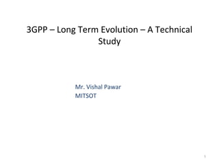
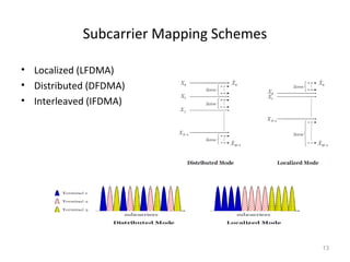
![Time domain signals of LFDMA, DFDMA and
IFDMA[20]
15](https://image.slidesharecdn.com/mitsotmcnelte-150406002332-conversion-gate01/85/3GPP-Long-Term-Evolution-15-320.jpg)
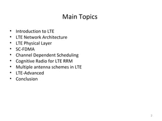
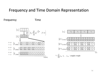
![PAPR characteristics of an SC-FDMA signal [20]
Comparison of the CCDF of PAPR for LFDMA, DFDMA, IFDMA and
OFDMA
16](https://image.slidesharecdn.com/mitsotmcnelte-150406002332-conversion-gate01/85/3GPP-Long-Term-Evolution-16-320.jpg)
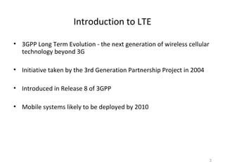
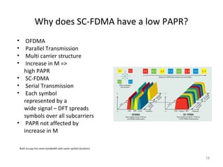
![Effect of roll-off factor, alpha on the PAPR[20]
17](https://image.slidesharecdn.com/mitsotmcnelte-150406002332-conversion-gate01/85/3GPP-Long-Term-Evolution-17-320.jpg)


The document presents a technical study on Long Term Evolution (LTE), detailing its architecture, physical layer, and features such as single-carrier frequency division multiple access (SC-FDMA) and cognitive radio for resource management. It outlines the requirements for LTE and introduces LTE Advanced, which aims to fulfill the International Mobile Telecommunications (IMT) Advanced standards for 4G technology. Additionally, the document discusses channel-dependent scheduling and multiple antenna schemes to enhance performance and throughput in LTE networks.


