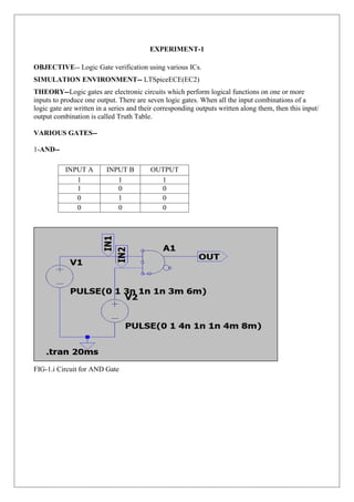
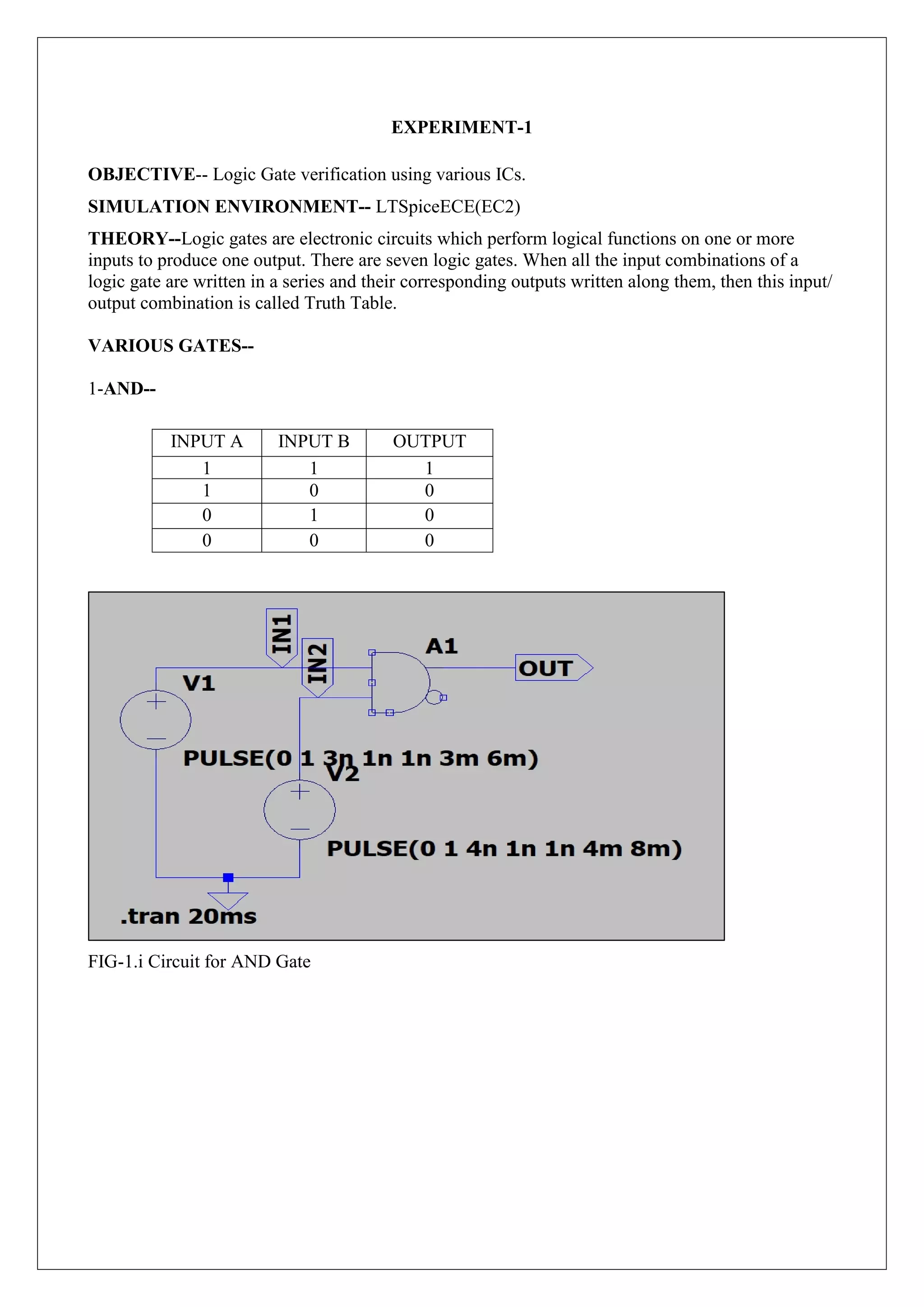
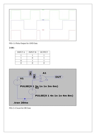
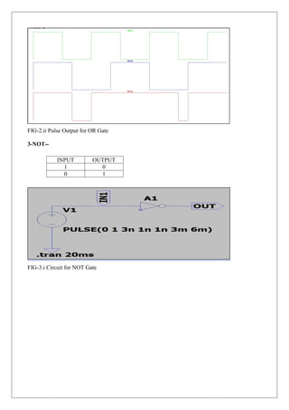
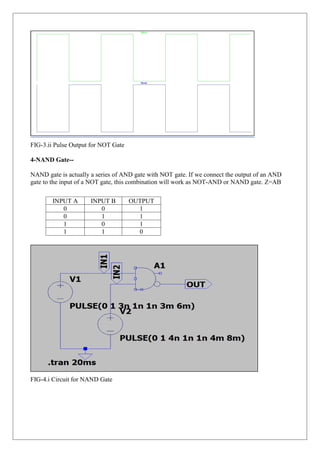
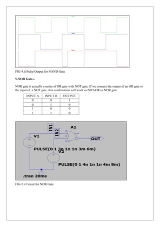
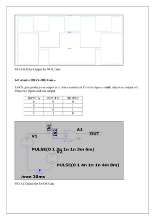
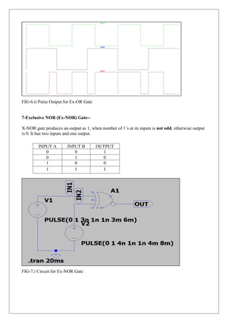
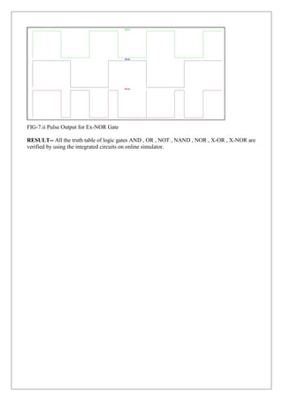
The document summarizes an experiment to verify the logic gates AND, OR, NOT, NAND, NOR, X-OR, and X-NOR using an online circuit simulator. It describes the objective as verifying logic gates using various integrated circuits. For each gate, it provides the circuit diagram, truth table, and pulse output diagram. It concludes that the truth tables for all gates were verified using integrated circuits on the online simulator.
1. EXPERIMENT-1
OBJECTIVE-- Logic Gate verification using various ICs.
SIMULATION ENVIRONMENT-- LTSpiceECE(EC2)
THEORY--Logic gates are electronic circuits which perform logical functions on one or more
inputs to produce one output. There are seven logic gates. When all the input combinations of a
logic gate are written in a series and their corresponding outputs written along them, then this input/
output combination is called Truth Table.
VARIOUS GATES--
1-AND--
FIG-1.i Circuit for AND Gate
INPUT A INPUT B OUTPUT
1 1 1
1 0 0
0 1 0
0 0 0
2. FIG-1.ii Pulse Output for AND Gate
2-OR--
FIG-2.i Circuit for OR Gate
INPUT A INPUT B OUTPUT
1 1 1
1 0 1
0 1 1
0 0 0
3. FIG-2.ii Pulse Output for OR Gate
3-NOT--
FIG-3.i Circuit for NOT Gate
INPUT OUTPUT
1 0
0 1
4. FIG-3.ii Pulse Output for NOT Gate
4-NAND Gate--
NAND gate is actually a series of AND gate with NOT gate. If we connect the output of an AND
gate to the input of a NOT gate, this combination will work as NOT-AND or NAND gate. Z=AB
FIG-4.i Circuit for NAND Gate
INPUT A INPUT B OUTPUT
0 0 1
0 1 1
1 0 1
1 1 0
5. FIG-4.ii Pulse Output for NAND Gate
5-NOR Gate--
NOR gate is actually a series of OR gate with NOT gate. If we connect the output of an OR gate to
the input of a NOT gate, this combination will work as NOT-OR or NOR gate.
FIG-5.i Circuit for NOR Gate
INPUT A INPUT B OUTPUT
0 0 1
0 1 0
1 0 0
1 1 0
6. FIG-5.ii Pulse Output for NOR Gate
6-Exclusive OR (X-OR) Gate--
Ex-OR gate produces an output as 1, when number of 1’s at its inputs is odd, otherwise output is 0.
It has two inputs and one output.
FIG-6.i Circuit for Ex-OR Gate
INPUT A INPUT B OUTPUT
0 0 0
0 1 1
1 0 1
1 1 0
7. FIG-6.ii Pulse Output for Ex-OR Gate
7-Exclusive NOR (Ex-NOR) Gate--
X-NOR gate produces an output as 1, when number of 1’s at its inputs is not odd, otherwise output
is 0. It has two inputs and one output.
FIG-7.i Circuit for Ex-NOR Gate
INPUT A INPUT B OUTPUT
0 0 1
0 1 0
1 0 0
1 1 1
8. FIG-7.ii Pulse Output for Ex-NOR Gate
RESULT-- All the truth table of logic gates AND , OR , NOT , NAND , NOR , X-OR , X-NOR are
verified by using the integrated circuits on online simulator.