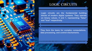
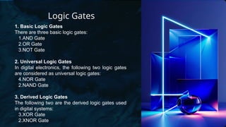
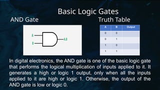
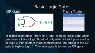
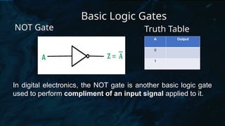
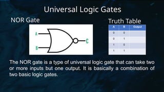
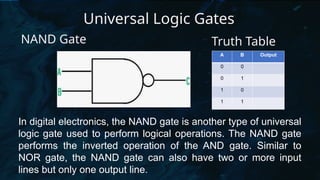
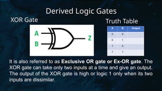
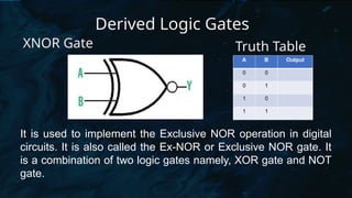
Introduction to Logic
Circuits
Presented by:
KYREL JOY P. PABLO
Date: 07|04|2024
Objectives:
1.Identify the symbols and functions of logic
gates.
2.Construct and design truth tables for each logic
gates.
3.Give importance on the uses of logic circuits.
KP
Logic circuits are the fundamental building
blocks of modern digital systems. They operate
on binary values, 0 and 1, representing "false"
and "true" respectively.
They form the basis for complex computations,
data processing, and control mechanisms.
LOGIC CIRCUITS
Logic Gates
A logic gate is an electronic circuit designed
by using electronic components like diodes,
transistors, resistors, and more. As the name
implies, a logic gate is designed to perform
logical operations in digital systems like
computers, communication systems, etc.
Logic Gates
1. Basic Logic Gates
There are three basic logic gates:
1.AND Gate
2.OR Gate
3.NOT Gate
2. Universal Logic Gates
In digital electronics, the following two logic gates
are considered as universal logic gates:
4.NOR Gate
2.NAND Gate
3. Derived Logic Gates
The following two are the derived logic gates used
in digital systems:
3.XOR Gate
2.XNOR Gate
Basic Logic Gates
AND Gate
In digital electronics, the AND gate is one of the basic logic gate
that performs the logical multiplication of inputs applied to it. It
generates a high or logic 1 output, only when all the inputs
applied to it are high or logic 1. Otherwise, the output of the
AND gate is low or logic 0.
A B Output
0 0
0 1
1 0
1 1
Truth Table
Basic Logic Gates
OR Gate
In digital electronics, there is a type of basic logic gate which
produces a low or logic 0 output only when its all inputs are low
or logic 0. For all other input combinations, the output of the OR
gate is high or logic 1. This logic gate is termed as OR gate.
A B Output
0 0
0 1
1 0
1 1
Truth Table
Basic Logic Gates
NOT Gate
In digital electronics, the NOT gate is another basic logic gate
used to perform compliment of an input signal applied to it.
A Output
0
1
Truth Table
Universal Logic Gates
NOR Gate
The NOR gate is a type of universal logic gate that can take two
or more inputs but one output. It is basically a combination of
two basic logic gates.
A B Output
0 0
0 1
1 0
1 1
Truth Table
Universal Logic Gates
NAND Gate
In digital electronics, the NAND gate is another type of universal
logic gate used to perform logical operations. The NAND gate
performs the inverted operation of the AND gate. Similar to
NOR gate, the NAND gate can also have two or more input
lines but only one output line.
A B Output
0 0
0 1
1 0
1 1
Truth Table
Derived Logic Gates
XOR Gate
It is also referred to as Exclusive OR gate or Ex-OR gate. The
XOR gate can take only two inputs at a time and give an output.
The output of the XOR gate is high or logic 1 only when its two
inputs are dissimilar.
A B Output
0 0
0 1
1 0
1 1
Truth Table
Derived Logic Gates
XNOR Gate
It is used to implement the Exclusive NOR operation in digital
circuits. It is also called the Ex-NOR or Exclusive NOR gate. It
is a combination of two logic gates namely, XOR gate and NOT
gate.
A B Output
0 0
0 1
1 0
1 1
Truth Table
Group Activity: Exploring Logic Circuits
Assignment:
Research and write a brief report on a real-world
application of logic circuits.
Thank You😊

Introduction-to-Logic-Circuits PowerPoint Presentaion

  • 1.
    Introduction to Logic Circuits Presentedby: KYREL JOY P. PABLO Date: 07|04|2024
  • 2.
    Objectives: 1.Identify the symbolsand functions of logic gates. 2.Construct and design truth tables for each logic gates. 3.Give importance on the uses of logic circuits.
  • 4.
    KP Logic circuits arethe fundamental building blocks of modern digital systems. They operate on binary values, 0 and 1, representing "false" and "true" respectively. They form the basis for complex computations, data processing, and control mechanisms. LOGIC CIRCUITS
  • 5.
    Logic Gates A logicgate is an electronic circuit designed by using electronic components like diodes, transistors, resistors, and more. As the name implies, a logic gate is designed to perform logical operations in digital systems like computers, communication systems, etc.
  • 6.
    Logic Gates 1. BasicLogic Gates There are three basic logic gates: 1.AND Gate 2.OR Gate 3.NOT Gate 2. Universal Logic Gates In digital electronics, the following two logic gates are considered as universal logic gates: 4.NOR Gate 2.NAND Gate 3. Derived Logic Gates The following two are the derived logic gates used in digital systems: 3.XOR Gate 2.XNOR Gate
  • 7.
    Basic Logic Gates ANDGate In digital electronics, the AND gate is one of the basic logic gate that performs the logical multiplication of inputs applied to it. It generates a high or logic 1 output, only when all the inputs applied to it are high or logic 1. Otherwise, the output of the AND gate is low or logic 0. A B Output 0 0 0 1 1 0 1 1 Truth Table
  • 8.
    Basic Logic Gates ORGate In digital electronics, there is a type of basic logic gate which produces a low or logic 0 output only when its all inputs are low or logic 0. For all other input combinations, the output of the OR gate is high or logic 1. This logic gate is termed as OR gate. A B Output 0 0 0 1 1 0 1 1 Truth Table
  • 9.
    Basic Logic Gates NOTGate In digital electronics, the NOT gate is another basic logic gate used to perform compliment of an input signal applied to it. A Output 0 1 Truth Table
  • 10.
    Universal Logic Gates NORGate The NOR gate is a type of universal logic gate that can take two or more inputs but one output. It is basically a combination of two basic logic gates. A B Output 0 0 0 1 1 0 1 1 Truth Table
  • 11.
    Universal Logic Gates NANDGate In digital electronics, the NAND gate is another type of universal logic gate used to perform logical operations. The NAND gate performs the inverted operation of the AND gate. Similar to NOR gate, the NAND gate can also have two or more input lines but only one output line. A B Output 0 0 0 1 1 0 1 1 Truth Table
  • 12.
    Derived Logic Gates XORGate It is also referred to as Exclusive OR gate or Ex-OR gate. The XOR gate can take only two inputs at a time and give an output. The output of the XOR gate is high or logic 1 only when its two inputs are dissimilar. A B Output 0 0 0 1 1 0 1 1 Truth Table
  • 13.
    Derived Logic Gates XNORGate It is used to implement the Exclusive NOR operation in digital circuits. It is also called the Ex-NOR or Exclusive NOR gate. It is a combination of two logic gates namely, XOR gate and NOT gate. A B Output 0 0 0 1 1 0 1 1 Truth Table
  • 14.
  • 15.
    Assignment: Research and writea brief report on a real-world application of logic circuits.
  • 16.