This document discusses various terminology related to the MAC sublayer, including:
1. The station model consisting of independent stations that generate frames for transmission.
2. The single channel assumption where a single channel is available for all communication.
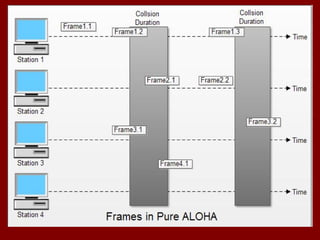
3. The collision assumption where if two frames are transmitted simultaneously they will overlap and be garbled.
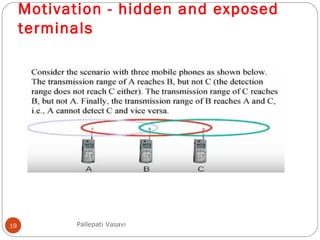
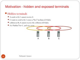
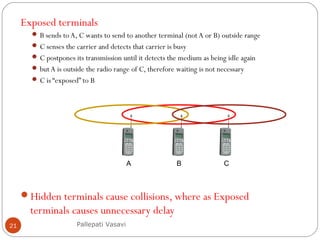
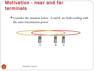
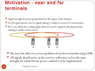
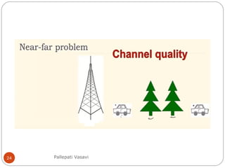
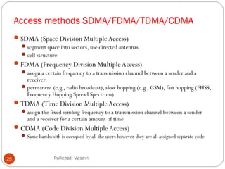
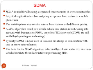
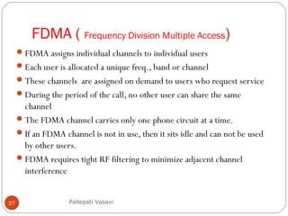
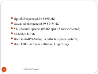
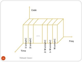
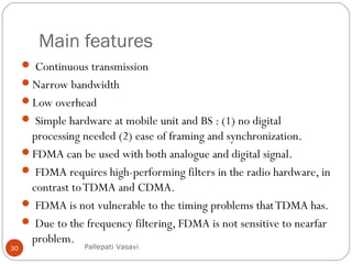
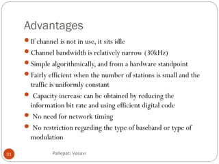
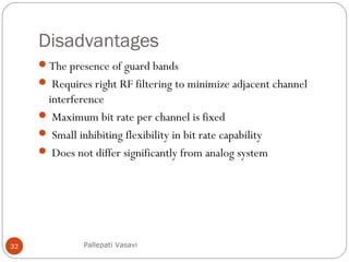
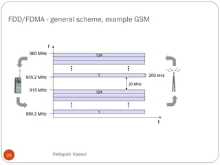
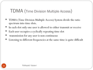
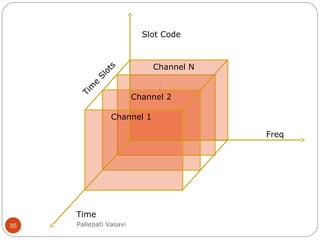
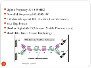
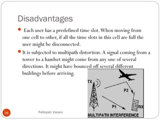
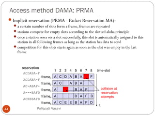
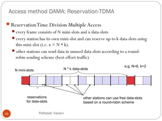
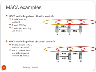
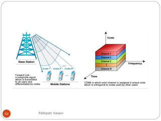
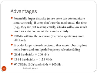
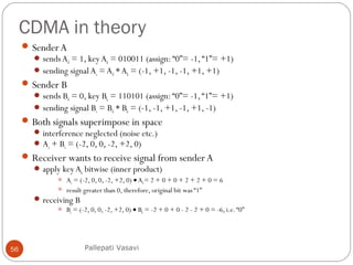
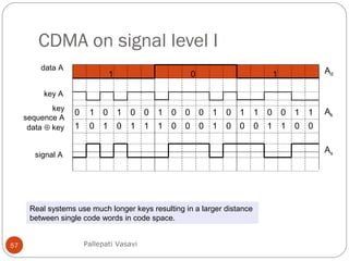
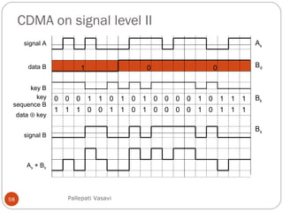
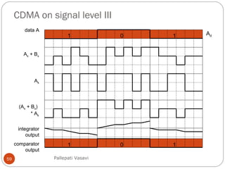
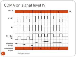
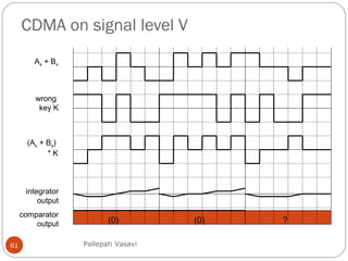
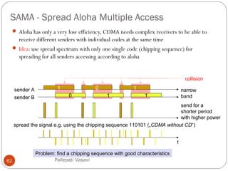
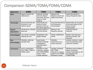
It then covers concepts such as carrier sensing, hidden and exposed terminals, and near and far terminals that create challenges for wireless networks. Finally, it introduces various multiple access methods including SDMA, FDMA, TDMA, and CDMA.