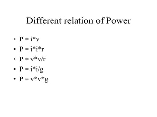
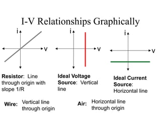
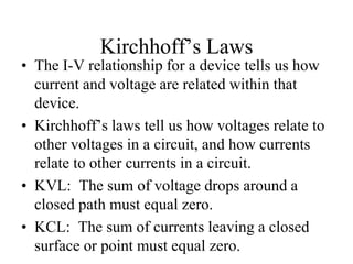
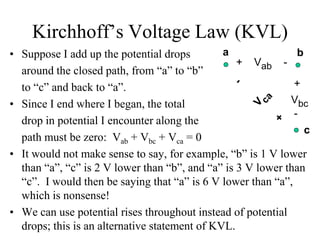
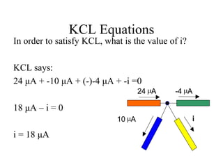
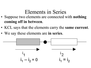
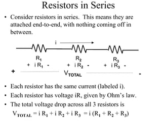
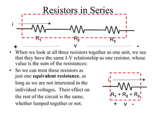
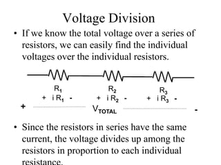
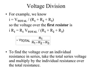
Electric Circuit Analysis
Adnan Yousaf
Lecture 5
Dependent and Independent Sources
• An independent source establish a voltage
or current in a circuit without relying on
voltages or currents elsewhere in circuit.
• A dependent source establish a voltage or
current whose value depend on voltages or
currents elsewhere in circuit.
• Diagram
• Example
Different relation of Power
• P = i*v
• P = i*i*r
• P = v*v/r
• P = i*i/g
• P = v*v*g
I-V Relationships Graphically
i
v
Resistor: Line
through origin with
slope 1/R
i
v
Ideal Voltage
Source: Vertical
line
i
v
Ideal Current
Source:
Horizontal line
Wire: Air:Vertical line
through origin
Horizontal line
through origin
Kirchhoff’s Laws
• The I-V relationship for a device tells us how
current and voltage are related within that
device.
• Kirchhoff’s laws tell us how voltages relate to
other voltages in a circuit, and how currents
relate to other currents in a circuit.
• KVL: The sum of voltage drops around a
closed path must equal zero.
• KCL: The sum of currents leaving a closed
surface or point must equal zero.
Kirchhoff’s Voltage Law (KVL)
• Suppose I add up the potential drops
around the closed path, from “a” to “b”
to “c” and back to “a”.
• Since I end where I began, the total
drop in potential I encounter along the
path must be zero: Vab + Vbc + Vca = 0
• It would not make sense to say, for example, “b” is 1 V lower
than “a”, “c” is 2 V lower than “b”, and “a” is 3 V lower than
“c”. I would then be saying that “a” is 6 V lower than “a”,
which is nonsense!
• We can use potential rises throughout instead of potential
drops; this is an alternative statement of KVL.
a b
c
+ Vab -
+
Vbc
-
KVL Tricks
• A voltage rise is a negative voltage drop.
• Look at the first sign you encounter on
each element when tracing the closed path.
If it is a “-”, it is a voltage rise and you will
insert a “-” to rewrite as a drop.
+
-
V2
Path
+
-
V1
Path
Along a path, I might encounter a voltage
which is labeled as a voltage drop (in the
direction I’m going). The sum of these
voltage drops must equal zero.
I might encounter a voltage which is
labeled as a voltage rise (in the direction
I’m going). This rise can be viewed as a
“negative drop”. Rewrite:
+
-V2
Path
-
Writing KVL Equations
What does KVL
say about the
voltages along
these 3 paths?
Path 1: 0vvv b2a 
Path 2: 0vvv c3b 
Path 3: 0vvvv c32a 
vc
va
+

+

3
21
+ 
vb
v3v2
+
+
-
a b c
Elements in Series
• Suppose two elements are connected with nothing
coming off in between.
• KCL says that the elements carry the same current.
• We say these elements are in series.
i1 = i2i1 – i2 = 0
Kirchhoff’s Current Law (KCL)
• Electrons don’t just disappear or get trapped (in our
analysis).
• Therefore, the sum of all current entering a closed
surface or point must equal zero—whatever goes in
must come out.
• Remember that current leaving a closed surface can be
interpreted as a negative current entering:
i1 is the same
statement as
-i1
KCL Equations
In order to satisfy KCL, what is the value of i?
KCL says:
24 μA + -10 μA + (-)-4 μA + -i =0
18 μA – i = 0
i = 18 μA
i10 mA
24 mA -4 mA
Elements in Series
• Suppose two elements are connected with nothing
coming off in between.
• KCL says that the elements carry the same current.
• We say these elements are in series.
i1 = i2i1 – i2 = 0
Resistors in Series
• Consider resistors in series. This means they are
attached end-to-end, with nothing coming off in
between.
• Each resistor has the same current (labeled i).
• Each resistor has voltage iR, given by Ohm’s law.
• The total voltage drop across all 3 resistors is
VTOTAL = i R1 + i R2 + i R3 = i (R1 + R2 + R3)
i
R1 R2 R3
+ i R1 - + i R2 - + i R3 -
+ -VTOTAL
Resistors in Series
• When we look at all three resistors together as one unit, we see
that they have the same I-V relationship as one resistor, whose
value is the sum of the resistances:
• So we can treat these resistors as
just one equivalent resistance, as
long as we are not interested in the
individual voltages. Their effect on
the rest of the circuit is the same,
whether lumped together or not.
i
R1 R2 R3
+ -v
i
+ v -
R1 + R2 + R3
Voltage Division
• If we know the total voltage over a series of
resistors, we can easily find the individual
voltages over the individual resistors.
• Since the resistors in series have the same
current, the voltage divides up among the
resistors in proportion to each individual
R1 R2 R3
+ i R1 - + i R2 - + i R3 -
+ -VTOTAL
Voltage Division
• For example, we know
i = VTOTAL / (R1 + R2 + R3)
so the voltage over the first resistor is
i R1 = R1 VTOTAL / (R1 + R2 + R3)
• To find the voltage over an individual
resistance in series, take the total series voltage
and multiply by the individual resistance over
the total resistance.
3R2R1R
1R
TOTALV



Linear circuit analysis 2

  • 1.
  • 2.
    Dependent and IndependentSources • An independent source establish a voltage or current in a circuit without relying on voltages or currents elsewhere in circuit. • A dependent source establish a voltage or current whose value depend on voltages or currents elsewhere in circuit.
  • 3.
  • 4.
    Different relation ofPower • P = i*v • P = i*i*r • P = v*v/r • P = i*i/g • P = v*v*g
  • 5.
    I-V Relationships Graphically i v Resistor:Line through origin with slope 1/R i v Ideal Voltage Source: Vertical line i v Ideal Current Source: Horizontal line Wire: Air:Vertical line through origin Horizontal line through origin
  • 6.
    Kirchhoff’s Laws • TheI-V relationship for a device tells us how current and voltage are related within that device. • Kirchhoff’s laws tell us how voltages relate to other voltages in a circuit, and how currents relate to other currents in a circuit. • KVL: The sum of voltage drops around a closed path must equal zero. • KCL: The sum of currents leaving a closed surface or point must equal zero.
  • 7.
    Kirchhoff’s Voltage Law(KVL) • Suppose I add up the potential drops around the closed path, from “a” to “b” to “c” and back to “a”. • Since I end where I began, the total drop in potential I encounter along the path must be zero: Vab + Vbc + Vca = 0 • It would not make sense to say, for example, “b” is 1 V lower than “a”, “c” is 2 V lower than “b”, and “a” is 3 V lower than “c”. I would then be saying that “a” is 6 V lower than “a”, which is nonsense! • We can use potential rises throughout instead of potential drops; this is an alternative statement of KVL. a b c + Vab - + Vbc -
  • 8.
    KVL Tricks • Avoltage rise is a negative voltage drop. • Look at the first sign you encounter on each element when tracing the closed path. If it is a “-”, it is a voltage rise and you will insert a “-” to rewrite as a drop. + - V2 Path + - V1 Path Along a path, I might encounter a voltage which is labeled as a voltage drop (in the direction I’m going). The sum of these voltage drops must equal zero. I might encounter a voltage which is labeled as a voltage rise (in the direction I’m going). This rise can be viewed as a “negative drop”. Rewrite: + -V2 Path -
  • 9.
    Writing KVL Equations Whatdoes KVL say about the voltages along these 3 paths? Path 1: 0vvv b2a  Path 2: 0vvv c3b  Path 3: 0vvvv c32a  vc va +  +  3 21 +  vb v3v2 + + - a b c
  • 10.
    Elements in Series •Suppose two elements are connected with nothing coming off in between. • KCL says that the elements carry the same current. • We say these elements are in series. i1 = i2i1 – i2 = 0
  • 11.
    Kirchhoff’s Current Law(KCL) • Electrons don’t just disappear or get trapped (in our analysis). • Therefore, the sum of all current entering a closed surface or point must equal zero—whatever goes in must come out. • Remember that current leaving a closed surface can be interpreted as a negative current entering: i1 is the same statement as -i1
  • 12.
    KCL Equations In orderto satisfy KCL, what is the value of i? KCL says: 24 μA + -10 μA + (-)-4 μA + -i =0 18 μA – i = 0 i = 18 μA i10 mA 24 mA -4 mA
  • 13.
    Elements in Series •Suppose two elements are connected with nothing coming off in between. • KCL says that the elements carry the same current. • We say these elements are in series. i1 = i2i1 – i2 = 0
  • 14.
    Resistors in Series •Consider resistors in series. This means they are attached end-to-end, with nothing coming off in between. • Each resistor has the same current (labeled i). • Each resistor has voltage iR, given by Ohm’s law. • The total voltage drop across all 3 resistors is VTOTAL = i R1 + i R2 + i R3 = i (R1 + R2 + R3) i R1 R2 R3 + i R1 - + i R2 - + i R3 - + -VTOTAL
  • 15.
    Resistors in Series •When we look at all three resistors together as one unit, we see that they have the same I-V relationship as one resistor, whose value is the sum of the resistances: • So we can treat these resistors as just one equivalent resistance, as long as we are not interested in the individual voltages. Their effect on the rest of the circuit is the same, whether lumped together or not. i R1 R2 R3 + -v i + v - R1 + R2 + R3
  • 16.
    Voltage Division • Ifwe know the total voltage over a series of resistors, we can easily find the individual voltages over the individual resistors. • Since the resistors in series have the same current, the voltage divides up among the resistors in proportion to each individual R1 R2 R3 + i R1 - + i R2 - + i R3 - + -VTOTAL
  • 17.
    Voltage Division • Forexample, we know i = VTOTAL / (R1 + R2 + R3) so the voltage over the first resistor is i R1 = R1 VTOTAL / (R1 + R2 + R3) • To find the voltage over an individual resistance in series, take the total series voltage and multiply by the individual resistance over the total resistance. 3R2R1R 1R TOTALV  