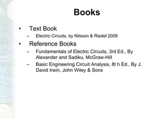
Linear Circuit Analysis
Dr.Muhammad Talha Gul
15-11-20181IET, Gomal University, D.I.Khan
Introduction to Linear Circuit
Analysis
Introduction Circuits for Electrical and Computer Engineering:
By
James W. Nilsson, Susan A. Riedel
Fundamentals of Electric Circuits
By
Charles K Alexander, Mathew N O Sadiku
Resource Person: Dr. Muhammad Talha Gul
Assistant Professor, FET, Superior University, Lahore
Books
• Text Book
– Electric Circuits, by Nilsson & Riedel 2009
• Reference Books
– Fundamentals of Electric Circuits, 3rd Ed., By
Alexander and Sadiku, McGraw-Hill
– Basic Engineering Circuit Analysis, 8t h Ed., By J.
David Irwin, John Wiley & Sons
Class Information
Meeting time: All week after class.
Email ID: talha.gul@superior.edu.pk
• Everything will be discuss there, including:
– Syllabus.
– News.
– Projects, etc
Course Objective
• Cover topics on Linear Circuit Analysis.
• Emphasis on Circuits Variables.
• Emphasis on Circuits Simplification techniques.
Class Format
• Research papers and Text Book.
• In-class discussion.
– All students must have read papers beforehand.
Grading
• Mid exam: 20 ~ 25 %
• Quizs: 10%
• Assignments : 10%
• Final exam: 50%
• Project: 10%. ( If applicable otherwise adjusted )
• In-class participation: 5%
• Attendance 5%
• Projects, home works, and the exam are INDIVIDUAL but
till not decided.
• Academic integrity violations will not be tolerated.
– Results in failing the class automatically and more…
– If there are questions, don’t hesitate to ask.
Projects
• Projects will be graded based on:
– Content: 20%
– Report: 20%
– In-class presentation/demo: 15%.
• List of suggested projects will be available soon.
• Project suggestions are also welcome.
Reading List
• Initial set of papers
• Papers will be updated as we go.
– Stay tuned for updates as papers get added.
• Lot’s of papers!
Today
• Introduction.
• Basic concepts.
• Terminology.
Course Aims
• This course is the foundation on which most other
courses in electrical engineering curriculum rest.
• It is designed as an introductory course in linear
circuit analysis.
• Subject areas included are, basic circuit
quantities, voltage and currents, resistive circuits,
Kirchhof’s Laws, nodal and mesh analysis,
linearity, source transformation, Thevenin’s and
Norton’s theorems, maximum power transfer,
Capacitance, Inductance, RC, RL, RLC circuits,
Sinusoidal response, Phasors and Introduction to
Op Amp is also included.
Covered Topics (Tentative)
• Electrical Circuits: An Overview
• The International System of Units
• Circuit Analysis: An Overview
• Charge , Current , Voltage and Power
Electrical Circuits: An Overview
Transmit and receive electric signal
1. Communication Systems
2. Computer Systems
3. Control Systems
4. Power Systems
5. Signal Processing Systems
International System of Units
• Length
• Mass
• Time
• Temperature
• Electric current
• Amount of substance
• Luminous Intensity
• Fundamental quantities
– Charge
– Current
– Voltage
– Power
• Fundamental concern
– Current-Voltage Relationship
• Fundamental elements
– Resistor
– Voltage Source
– Current Source
Charge
• You are already familiar with the idea of
charge from chemistry or physics.
• We say a proton has a positive charge, and an
electron has a negative charge.
• Charge is measured in units called Coulombs,
abbreviated C.
1 proton = 1.6 x 10⁻¹⁹ C
1 electron = -1.6 x 10⁻¹⁹ C
Electric Field
• We know that opposite charges attract each other, and
like charges repel.
• The presence of a charged particle creates an electric
field. Other phenomena also create an electric field.
• The electric field is a lot like gravity. It can point in
different directions and have different strength
depending on location.
+
Earth
Vector fields are like wind maps
from your weather forecast.
Voltage
• It takes energy to move a proton against the direction of
an electric field (just like it takes energy to lift an object off
the ground, against gravity).
• Suppose it takes (positive) energy to move a proton from
point a to point b. Then we say point b is at a higher
electric potential than point a.
• The difference in electric potential between two points is
called voltage. Voltage, measured in Volts (V) indicates
how much energy it takes to move a charge from point to
point.
a b
+
Voltage Conventions
• Voltage is always measured between two points (just like
distance). We need to specify the “start” and “finish”.
• We could write
saying that b is 5 V
higher than a.
• Or, we could write
saying that a is -5 V
higher than b.
• When we put down a + and a – to specify a voltage, it is
simply a reference frame. We are not making a
statement about which point actually has the higher
potential, since the voltage in between can be negative!
+
a b
- 5 V +
+ - 5 V -
Examples
1.5V1.5V 9V
A B C D
What is VAD ?
Find V1 and Vx.
1.5V1.5V 9V
A B C D
V1
VX
-
The flat end of the battery is at lower
potential than the “bump” end.
-1.5 V + -1.5 V + 9 V = 6 V
V1 = 1.5 V
VX = -6 V
Voltage Conventions: Ground
• Many times, a common point will be used as the starting (-)
point for several voltage measurements. This common
point is called common or ground.
• We may define a voltage at point “a” with respect to ground.
This refers to the voltage with + reference at “a” and –
reference at ground.
• Voltages with respect to ground
are often denoted using a
single subscript:
• Notice the symbol for ground.
Also seen is
Va
a
+
-
z
Current: Moving Charge
• An electric field (or applied energy) can cause charge to
move.
• The amount of charge per time unit moving past a point is
called current.
• Current is measured in Coulombs per second, which are
called Amperes (abbreviated A and called Amps for short).
• Mathematically speaking,
where i is current in A, q is
charge in C, and t is time in s
• Even though it is usually electrons that do the moving,
current is defined as the flow of positive charge.
dt
dq
i 
Current Reference Direction
• Current also needs a reference frame. To define a
current, draw an arrow:
• This says “the current moving through the device
from left to right is 5 A”.
• We could also say, “the current moving through the
device from right to left is -5 A”.
• Drawing an arrow does not make a statement about
the direction the current is actually going. It is just a
reference frame. You can draw arrows however you
want when you need to solve for currents.
5 A -5 A
Resistance
• Current is due the ability of electrons to break away from
atoms and move around.
• In some materials, like metals, where there are few
valence electrons, little energy is needed to break bonds
and move an electron.
• In other materials, a strong electric field (voltage) must be
applied to break the bonds. These materials are said to
have a higher resistance.
• Resistance, measured in Ohms (Ω), indicates how much
voltage is necessary to create a certain amount of current.
Power
• Power is the amount of energy absorbed or
generated per unit time. It is the time derivative of
energy, and it is measured in Watts (W).
• The power absorbed (or generated) by a device is
equal to the product of the current through the
device and the voltage over the device:
p = v i where p is power in W, v is voltage in V
and i is current in A.
• Sometimes this equation gives you the power
absorbed by the device, and sometimes it provides
the power generated by the device.
Power: Sign Convention
• Whether “p = v i” provides absorbed power or
generated power depends on the relationship
between the current and voltage directions.
• If the current i is referenced to flow from the “+”
terminal of v to the “-” terminal of v, then “p = v i”
provides the power absorbed.
• When the opposite is true, “p = v i” provides the
power generated.
i1 i2
+ Vdevice -
Power absorbed by
device = (Vdevice) (i1)
Power generated by
device = (Vdevice) (i2)
Power Calculations
Find the power absorbed by each element.
Element  :
Element  :
Element  :
Element  :




-
+
-
+
2 V
1 V
-+
3 V
-
+
1 V
2.5 mA
0.5 mA
3 mA
Power Calculations
Find the power absorbed by each element.
Element  :
Element  :
Element  :
Element  :




-
+
-
+
2 V
1 V
-+
3 V
-
+
1 V
2.5 mA
0.5 mA
3 mA
(3 V)(-3 mA) = -9 mW
(2 V)(3 mA) = 6 mW
(1 V)(0.5 mA) = 0.5 mW
(1 V)(2.5 mA) = 2.5 mW
Basic Circuit Elements
• Resistor
– Current is proportional to voltage (linear)
• Ideal Voltage Source
– Voltage is a given quantity, current is unknown
• Wire (Short Circuit)
– Voltage is zero, current is unknown
• Ideal Current Source
– Current is a given quantity, voltage is unknown
• Air (Open Circuit)
– Current is zero, voltage is unknown
Resistor
• The resistor has a current-
voltage relationship called
Ohm’s law:
v = i R
where R is the resistance in Ω,
i is the current in A, and v is the
voltage in V, with reference
directions as pictured.
• If R is given, once you know i, it is easy to find v and vice-versa.
• Since R is never negative, a resistor always absorbs power…
-
+
vR
i
Ideal Voltage Source
• The ideal voltage source explicitly defines
the voltage between its terminals.
– Constant (DC) voltage source: Vs = 5 V
– Examples: batteries, wall outlet, function generator,
…
• The ideal voltage source does not provide any
information about the current flowing through it.
• The current through the voltage source is defined by the
rest of the circuit to which the source is attached.
Current cannot be determined by the value of the
voltage.
• Do not assume that the current is zero!
+
-
Vs
Wire
• Wire has a very small resistance.
• For simplicity, we will idealize wire in the
following way: the potential at all points
on a piece of wire is the same,
regardless of the current going through it.
– Wire is a 0 V voltage source
– Wire is a 0 Ω resistor
Ideal Current Source
• The ideal current source sets the
value of the current running through it.
– Constant (DC) current source: Is = 2 A
– Examples: few in real life!
• The ideal current source has known current, but
unknown voltage.
• The voltage across the voltage source is defined by
the rest of the circuit to which the source is
attached.
• Voltage cannot be determined by the value of the
current.
• Do not assume that the voltage is zero!
Is
Air
• Many of us at one time, after walking on a carpet in winter,
have touched a piece of metal and seen a blue arc of light.
• That arc is current going through the air. So is a bolt of
lightning during a thunderstorm.
• However, these events are unusual. Air is usually a good
insulator and does not allow current to flow.
• For simplicity, we will idealize air in the following way:
current never flows through air (or a hole in a circuit),
regardless of the potential difference (voltage) present.
– Air is a 0 A current source
– Air is a very very big (infinite) resistor
• There can be nonzero voltage over air or a hole in a
circuit!
FET, Superior University 35
Questions?

Linear circuit analysis 1

  • 1.
    Linear Circuit Analysis Dr.MuhammadTalha Gul 15-11-20181IET, Gomal University, D.I.Khan
  • 2.
    Introduction to LinearCircuit Analysis Introduction Circuits for Electrical and Computer Engineering: By James W. Nilsson, Susan A. Riedel Fundamentals of Electric Circuits By Charles K Alexander, Mathew N O Sadiku Resource Person: Dr. Muhammad Talha Gul Assistant Professor, FET, Superior University, Lahore
  • 3.
    Books • Text Book –Electric Circuits, by Nilsson & Riedel 2009 • Reference Books – Fundamentals of Electric Circuits, 3rd Ed., By Alexander and Sadiku, McGraw-Hill – Basic Engineering Circuit Analysis, 8t h Ed., By J. David Irwin, John Wiley & Sons
  • 4.
    Class Information Meeting time:All week after class. Email ID: talha.gul@superior.edu.pk • Everything will be discuss there, including: – Syllabus. – News. – Projects, etc
  • 5.
    Course Objective • Covertopics on Linear Circuit Analysis. • Emphasis on Circuits Variables. • Emphasis on Circuits Simplification techniques.
  • 6.
    Class Format • Researchpapers and Text Book. • In-class discussion. – All students must have read papers beforehand.
  • 7.
    Grading • Mid exam:20 ~ 25 % • Quizs: 10% • Assignments : 10% • Final exam: 50% • Project: 10%. ( If applicable otherwise adjusted ) • In-class participation: 5% • Attendance 5% • Projects, home works, and the exam are INDIVIDUAL but till not decided. • Academic integrity violations will not be tolerated. – Results in failing the class automatically and more… – If there are questions, don’t hesitate to ask.
  • 8.
    Projects • Projects willbe graded based on: – Content: 20% – Report: 20% – In-class presentation/demo: 15%. • List of suggested projects will be available soon. • Project suggestions are also welcome.
  • 9.
    Reading List • Initialset of papers • Papers will be updated as we go. – Stay tuned for updates as papers get added. • Lot’s of papers!
  • 10.
    Today • Introduction. • Basicconcepts. • Terminology.
  • 11.
    Course Aims • Thiscourse is the foundation on which most other courses in electrical engineering curriculum rest. • It is designed as an introductory course in linear circuit analysis. • Subject areas included are, basic circuit quantities, voltage and currents, resistive circuits, Kirchhof’s Laws, nodal and mesh analysis, linearity, source transformation, Thevenin’s and Norton’s theorems, maximum power transfer, Capacitance, Inductance, RC, RL, RLC circuits, Sinusoidal response, Phasors and Introduction to Op Amp is also included.
  • 12.
    Covered Topics (Tentative) •Electrical Circuits: An Overview • The International System of Units • Circuit Analysis: An Overview • Charge , Current , Voltage and Power
  • 13.
    Electrical Circuits: AnOverview Transmit and receive electric signal 1. Communication Systems 2. Computer Systems 3. Control Systems 4. Power Systems 5. Signal Processing Systems
  • 14.
    International System ofUnits • Length • Mass • Time • Temperature • Electric current • Amount of substance • Luminous Intensity
  • 15.
    • Fundamental quantities –Charge – Current – Voltage – Power • Fundamental concern – Current-Voltage Relationship • Fundamental elements – Resistor – Voltage Source – Current Source
  • 16.
    Charge • You arealready familiar with the idea of charge from chemistry or physics. • We say a proton has a positive charge, and an electron has a negative charge. • Charge is measured in units called Coulombs, abbreviated C. 1 proton = 1.6 x 10⁻¹⁹ C 1 electron = -1.6 x 10⁻¹⁹ C
  • 17.
    Electric Field • Weknow that opposite charges attract each other, and like charges repel. • The presence of a charged particle creates an electric field. Other phenomena also create an electric field. • The electric field is a lot like gravity. It can point in different directions and have different strength depending on location. + Earth Vector fields are like wind maps from your weather forecast.
  • 18.
    Voltage • It takesenergy to move a proton against the direction of an electric field (just like it takes energy to lift an object off the ground, against gravity). • Suppose it takes (positive) energy to move a proton from point a to point b. Then we say point b is at a higher electric potential than point a. • The difference in electric potential between two points is called voltage. Voltage, measured in Volts (V) indicates how much energy it takes to move a charge from point to point. a b +
  • 19.
    Voltage Conventions • Voltageis always measured between two points (just like distance). We need to specify the “start” and “finish”. • We could write saying that b is 5 V higher than a. • Or, we could write saying that a is -5 V higher than b. • When we put down a + and a – to specify a voltage, it is simply a reference frame. We are not making a statement about which point actually has the higher potential, since the voltage in between can be negative! + a b - 5 V + + - 5 V -
  • 20.
    Examples 1.5V1.5V 9V A BC D What is VAD ? Find V1 and Vx. 1.5V1.5V 9V A B C D V1 VX - The flat end of the battery is at lower potential than the “bump” end. -1.5 V + -1.5 V + 9 V = 6 V V1 = 1.5 V VX = -6 V
  • 21.
    Voltage Conventions: Ground •Many times, a common point will be used as the starting (-) point for several voltage measurements. This common point is called common or ground. • We may define a voltage at point “a” with respect to ground. This refers to the voltage with + reference at “a” and – reference at ground. • Voltages with respect to ground are often denoted using a single subscript: • Notice the symbol for ground. Also seen is Va a + - z
  • 22.
    Current: Moving Charge •An electric field (or applied energy) can cause charge to move. • The amount of charge per time unit moving past a point is called current. • Current is measured in Coulombs per second, which are called Amperes (abbreviated A and called Amps for short). • Mathematically speaking, where i is current in A, q is charge in C, and t is time in s • Even though it is usually electrons that do the moving, current is defined as the flow of positive charge. dt dq i 
  • 23.
    Current Reference Direction •Current also needs a reference frame. To define a current, draw an arrow: • This says “the current moving through the device from left to right is 5 A”. • We could also say, “the current moving through the device from right to left is -5 A”. • Drawing an arrow does not make a statement about the direction the current is actually going. It is just a reference frame. You can draw arrows however you want when you need to solve for currents. 5 A -5 A
  • 24.
    Resistance • Current isdue the ability of electrons to break away from atoms and move around. • In some materials, like metals, where there are few valence electrons, little energy is needed to break bonds and move an electron. • In other materials, a strong electric field (voltage) must be applied to break the bonds. These materials are said to have a higher resistance. • Resistance, measured in Ohms (Ω), indicates how much voltage is necessary to create a certain amount of current.
  • 25.
    Power • Power isthe amount of energy absorbed or generated per unit time. It is the time derivative of energy, and it is measured in Watts (W). • The power absorbed (or generated) by a device is equal to the product of the current through the device and the voltage over the device: p = v i where p is power in W, v is voltage in V and i is current in A. • Sometimes this equation gives you the power absorbed by the device, and sometimes it provides the power generated by the device.
  • 26.
    Power: Sign Convention •Whether “p = v i” provides absorbed power or generated power depends on the relationship between the current and voltage directions. • If the current i is referenced to flow from the “+” terminal of v to the “-” terminal of v, then “p = v i” provides the power absorbed. • When the opposite is true, “p = v i” provides the power generated. i1 i2 + Vdevice - Power absorbed by device = (Vdevice) (i1) Power generated by device = (Vdevice) (i2)
  • 27.
    Power Calculations Find thepower absorbed by each element. Element  : Element  : Element  : Element  :     - + - + 2 V 1 V -+ 3 V - + 1 V 2.5 mA 0.5 mA 3 mA
  • 28.
    Power Calculations Find thepower absorbed by each element. Element  : Element  : Element  : Element  :     - + - + 2 V 1 V -+ 3 V - + 1 V 2.5 mA 0.5 mA 3 mA (3 V)(-3 mA) = -9 mW (2 V)(3 mA) = 6 mW (1 V)(0.5 mA) = 0.5 mW (1 V)(2.5 mA) = 2.5 mW
  • 29.
    Basic Circuit Elements •Resistor – Current is proportional to voltage (linear) • Ideal Voltage Source – Voltage is a given quantity, current is unknown • Wire (Short Circuit) – Voltage is zero, current is unknown • Ideal Current Source – Current is a given quantity, voltage is unknown • Air (Open Circuit) – Current is zero, voltage is unknown
  • 30.
    Resistor • The resistorhas a current- voltage relationship called Ohm’s law: v = i R where R is the resistance in Ω, i is the current in A, and v is the voltage in V, with reference directions as pictured. • If R is given, once you know i, it is easy to find v and vice-versa. • Since R is never negative, a resistor always absorbs power… - + vR i
  • 31.
    Ideal Voltage Source •The ideal voltage source explicitly defines the voltage between its terminals. – Constant (DC) voltage source: Vs = 5 V – Examples: batteries, wall outlet, function generator, … • The ideal voltage source does not provide any information about the current flowing through it. • The current through the voltage source is defined by the rest of the circuit to which the source is attached. Current cannot be determined by the value of the voltage. • Do not assume that the current is zero! + - Vs
  • 32.
    Wire • Wire hasa very small resistance. • For simplicity, we will idealize wire in the following way: the potential at all points on a piece of wire is the same, regardless of the current going through it. – Wire is a 0 V voltage source – Wire is a 0 Ω resistor
  • 33.
    Ideal Current Source •The ideal current source sets the value of the current running through it. – Constant (DC) current source: Is = 2 A – Examples: few in real life! • The ideal current source has known current, but unknown voltage. • The voltage across the voltage source is defined by the rest of the circuit to which the source is attached. • Voltage cannot be determined by the value of the current. • Do not assume that the voltage is zero! Is
  • 34.
    Air • Many ofus at one time, after walking on a carpet in winter, have touched a piece of metal and seen a blue arc of light. • That arc is current going through the air. So is a bolt of lightning during a thunderstorm. • However, these events are unusual. Air is usually a good insulator and does not allow current to flow. • For simplicity, we will idealize air in the following way: current never flows through air (or a hole in a circuit), regardless of the potential difference (voltage) present. – Air is a 0 A current source – Air is a very very big (infinite) resistor • There can be nonzero voltage over air or a hole in a circuit!
  • 35.