This document describes a graduate project submitted by Zainab Falaih Hasan Ulla Ahmed Ouda for the degree of Bachelor of Automated Manufacturing Engineering. The project involves designing and building a prototype of a black line tracking robot. The robot uses sensors and a microcontroller to follow a black line on a white surface and maneuver turns. It is intended to function autonomously within an automated factory environment. The document provides background on the project, acknowledges those involved in advising and supporting the work, and outlines the various chapters that will comprise the project report, including the robot design, hardware components, implementation details, results, and proposals for future work.

![1
Chapter one
Introduction
1.1 Linetracking definition
The line tracking is a self-operating robot that detects and follows a line that is drawn on the floor. The path
consists of a black line on a white surface (or it may be reverse of that). The control system used must sense a
line and maneuver the robot to stay on course, while constantly correcting the wrong moves using feedback
mechanism, thus forming a simple yet effective closed loop System. The robot is designed to follow very tight
curves.[1]
1.2 Literaturereview
In this section some of the existing tools and technologies developed so far in the field line tracking robots are
reviewed. Hymavathi & Vijay Kumar (2011) presented a paper on Design of a double line tracking using IR
sensors, op-amp and 8051 Microcontroller. Arora & Mengi (2011) presented a paper on line follower using IR
sensors and S12X Microcontroller. These techniques have a major drawback that they are color dependent. The
voltages outputted by the sensors depend on the color sensed. Hence they are not flexible. Also these IR sensors
are affected by other IR radiations if present in the same environment. The placement of sensors is also dependent
on the dimensions of the path. Also IR sensors have a limited lifetime and it’s difficult to debug faults.[6]
1.3 Objective
In the industry carriers are required to carry products from one manufacturing plant to another which are usually
in different buildings or separate blocks. Conventionally, carts or trucks were used with human drivers.
Unreliability and inefficiency in this part of the assembly line formed the weakest link. The project objective is
to automate this sector, using carts to follow a line instead of laying railway tracks which are both costly and an
inconvenience.[1]](https://image.slidesharecdn.com/ad727556-e6ca-4fbb-b84c-040e59ae1d64-160916165502-180128145401/85/Line-follower-robot-9-320.jpg)
![2
1.4 Scopes of project
• The robot must be capable of following a line.
• It should be capable of taking various degrees of turns
• It must be prepared of a situation that it runs into a territory which has no line to follow.
• The robot must also be capable of following a line even if it has breaks.
• The robot must be insensitive to environmental factors such as lighting and noise.
• The color of the line must not be a factor as long as it is darker than the surroundings.
1.5 Advantages
Can be moved on the straight or arc-shaped railways to carry many different kinds of stuff.
Different shape, size and weight can be carry.
Flexible and intelligent.
Time consuming.
Used to reduce manufacturing and labor costs while increasing productivity and efficiency.
Robot movement is automatic.
It is used for long distance applications.
Simplicity of building.
Used in home, industrial automations etc.[8]
1.6 Disadvantages
Follows a black line about 1 or 2 inches in width on a white surface.
Simple robots with an additional sensors placed on them.
Needs a path to run either white or black since the IR rays should reflect from the particular path.
Slow speed and instability on different line thickness or hard angles.[8]](https://image.slidesharecdn.com/ad727556-e6ca-4fbb-b84c-040e59ae1d64-160916165502-180128145401/85/Line-follower-robot-10-320.jpg)
![3
Applications1.7
Industrial Applications: These robots can be used as automated equipment carriers in industries replacing
traditional conveyer belts, automatic storage, packaging, use as a handling materials vehicle inside the
factories, in harbors with the aid of robotic arm can make completely automated system of loading and
unloading from the ships.
Automobile applications: These robots can also be used as automatic cars running on roads with embedded
magnets.
Domestic applications: These can also be used at homes for domestic purposes like floor cleaning etc.
Guidance applications: These can be used in public places like shopping malls, museums etc. to provide
path guidance.
Medical applications: As a wheel chair for patients to use it, can be used in walking stick for blind persons
which react as an alarm when get out of the way instead of the motor, efficient automatic transportation of
goods, the goods typically transported by ATLIS System include carts of dietary/food items, medical/surgical
supplies (case carts), linens, trash, regulated medical waste, pharmaceuticals, items for decontamination
centers, and general housekeeping items.[1]](https://image.slidesharecdn.com/ad727556-e6ca-4fbb-b84c-040e59ae1d64-160916165502-180128145401/85/Line-follower-robot-11-320.jpg)
![4
Chapter two
Robot design
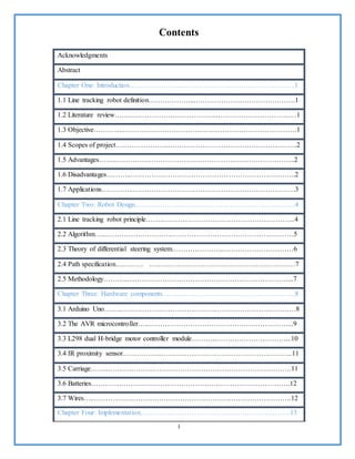
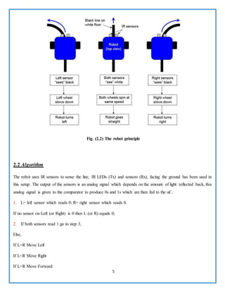
2.1 Line tracking robot principle
The working of a line follower robot is pretty straight forward. These robots have the capability to detect a
black/dark line on a lighter surface depending on the contrast. They estimate whether the line underneath them is
shifting towards their left/right as they move over them. Based on that estimation they give respective signals to
the motors to turn left/right so as to maintain a steady center with respect to the line.
These robots usually use an array of IR (Infrared) sensors in order to calculate the reflectance of the surface
beneath them. The basic criteria being that the black line will have a lesser reflectance value (black absorbs light)
than the lighter surface around it. This low value of reflectance is the parameter used to detect the position of the
line by the robot. The higher value of reflectance will be the surface around the line. So in this linear array of IR
sensors, if the leftmost/rightmost IR sensor presents the low value for reflectance, then the black line is towards
the left/right of the robot correspondingly. The controller then compensates for this by signaling the motor to go
in the opposite direction of the line. [2]
Fig. (2.1) Sensor Principle](https://image.slidesharecdn.com/ad727556-e6ca-4fbb-b84c-040e59ae1d64-160916165502-180128145401/85/Line-follower-robot-12-320.jpg)
![6
Go to step 4
3. Move clockwise if line was last seen on Right
Move counter clockwise if line was last seen on Left
Repeat step 3 till line is found.
4. Go to step 1.[3]
2.3 Theory of the differential steering system
The differential steering system is familiar from ordinary life because it is the arrangement used in a wheelchair.
Two wheels mounted on a single axis are independently powered and controlled, thus providing both drive and
steering. Additional passive wheels (usually casters) are provided for support. Most of us have an intuitive grasp
of the basic behavior of a differential steering system. If both drive wheels turn in tandem, the robot moves in a
straight line. If one wheel turns faster than the other, the robot follows a curved path. If the wheels turn at equal
speed, but in opposite directions,
the robot pivots.[8]
Fig. (2.3) Theory of differential steering system](https://image.slidesharecdn.com/ad727556-e6ca-4fbb-b84c-040e59ae1d64-160916165502-180128145401/85/Line-follower-robot-14-320.jpg)
![7
2.4 Path specifications
There are two colors chosen for the guide-path.
Guiding Color: very low reflection color (black) drawn on the ground, which form the path of the vehicle;
the basic width of the line is (200mm) which is a bit more than the space between the two sensors, this is to avoid
failures happening while turnings. In this case the sensor board may go out of the basis path and read the data
from the basic carpet of the shop floor which makes the plan unlikely and unpredictable.
Base Color: This color is a shiny color with high reflection (white) which the line follower sensor react with
to move the vehicle, it forms the basic platform of the factory or the place where the vehicle work in.[3]
Fig. (2.4) The path
2.5 Methodology
First we used the reflective optical sensors but when we experienced it the signal that gave us was too weak so
we used an amplifier circuit but also the signal wasn’t strong enough to operate and sense the line from a distance
,Then we changed the sensors into the IR proximity sensor and tested it by connecting it with the Arduino and
when we passed it over a white color path it gave us signal (1) and when we passed it over black path gave us
(zero) , then we started the hardware part of the project and the programing part using the C/C++ language and
finally it worked. For which we’re thankful for, as we have learnt much more in the processes.[3]](https://image.slidesharecdn.com/ad727556-e6ca-4fbb-b84c-040e59ae1d64-160916165502-180128145401/85/Line-follower-robot-15-320.jpg)
![8
Chapter three
Hardware component
3.1 ArduinoUno
The Uno is a microcontroller board based on the ATmega328P.It has 14 digital input/output pins (of which 6
can be used as PWM outputs), 6 analog inputs, a 16 MHz quartz crystal, a USB connection, a power jack, an
ICSP header and a reset button. It contains everything needed to support the microcontroller; simply connect it
to a computer with a USB cable or power it with a AC-to-DC adapter or battery to get started. You can tinker
with your UNO without worrying too much about doing something wrong, worst case scenario you can replace
the chip for a few dollars and start over again. "Uno" means one in Italian and was chosen to mark the release
of Arduino Software (IDE) 1.0. The Uno board and version 1.0 of Arduino Software (IDE) were the reference
versions of Arduino, now evolved to newer releases. The Uno board is the first in a series of USB Arduino
boards, and the evolved to newer releases. The Uno board is the first in a series of USB Arduino boards, and
the reference model for the Arduino platform; for an extensive list of current, past or outdated boards see the
Arduino index of boards.[1]
Fig. (3.1) Arduino UNO](https://image.slidesharecdn.com/ad727556-e6ca-4fbb-b84c-040e59ae1d64-160916165502-180128145401/85/Line-follower-robot-16-320.jpg)
![9
3.2 The AVR microcontroller
Atmel's AVR® microcontrollers have a RISC core running single cycle instructions and a well-defined I/O
structure that limits the need for external components. Internal oscillators, timers, UART, SPI, pull-up resistors,
pulse width modulation, ADC, analog comparator and watch-dog timers are some of the features you will find in
AVR devices.
AVR instructions are tuned to decrease the size of the program whether the code is written in C or Assembly.
With on-chip in-system programmable Flash and EEPROM, the AVR is a perfect choice in order to optimize cost
and get product to the market quickly.[4]
Fig. (3.2) AVR microcontrollers](https://image.slidesharecdn.com/ad727556-e6ca-4fbb-b84c-040e59ae1d64-160916165502-180128145401/85/Line-follower-robot-17-320.jpg)
![10
3.3 L298 Dual H-bridgeMotor Controllermodule
H- Bridges are typically used in controlling motors speed and direction, but can be used for other projects such
as driving the brightness of certain lighting projects such as high powered LED arrays.
An H-Bridge is a circuit that can drive a current in either polarity and controlled by *Pulse Width Modulation (P
WM).Pulse Width Modulation is a mean in controlling the duration of an electronic pulse.[4]
Fig. (3.3) L298 Dual H-bridge Motor Controller module
3.4 IR Proximitysensor
The IR Proximity sensor is one of the most commonly used sensors you will find these in automatic taps,
automatic door opening, etc. This sensor works on the principle of IR reflectance.
There is an IR LED (white / light blue in color) that’s constantly emitting emitting IR light. The light when
reflected back falls on the IR Receiver) LED / Photodiode (the black / dark blue color led) this received signal
is then Already a member? Sign in processed by an Op-Amp and the Op-Amp gives a HIGH signal. So the sensor
module will give a HIGH signal if there is an object in front of the LED's. The range of sensing can be varied by
adjusting the potentiometer on the sensor module. The maximum range of this module is only a few cms, so don't
expect to use this as a distance sensor. The module will not work when pointed at black objects as black
color tends to absorb the IR light program to trigger the Buzzer every time the sensor gives a high signal.[2]](https://image.slidesharecdn.com/ad727556-e6ca-4fbb-b84c-040e59ae1d64-160916165502-180128145401/85/Line-follower-robot-18-320.jpg)
![11
Fig. (3.4) The proximity sensor
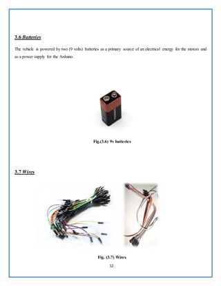
3.5 Carriage
Contain three tires used in the project taken from baby carriage, two of them are attached to the motors and the
third is restricted in movement only rotate forward and backward. Three tires are used instead of four to lessen
the friction while turning because there is no steering to rotate the tire.[3]
Fig. (3.5) Automation carriage](https://image.slidesharecdn.com/ad727556-e6ca-4fbb-b84c-040e59ae1d64-160916165502-180128145401/85/Line-follower-robot-19-320.jpg)
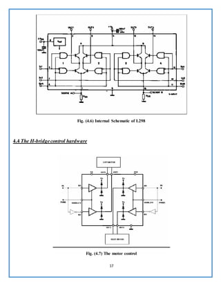
![18
The entire motor control circuitry is shown in the above figure along with the internal circuitry of the L298 motor
control IC. The table below clearly indicated the operation of the IC.
Table (1)
The total number of directional control signals required is 4; but as it can be observed in the above table, IN1 &
IN2 are complimentary (and so is IN3 & IN4) that is, both the inputs have to take the opposite states for a safe
operation. This is done by connecting DL to IN1 and L D to IN2. The same is done to IN3 & IN4. Now we have
1 directional control per motor. The ENABLE of each motor section is given PWM inputs to further improve on
the control. Now, each motor has a direction control and a speed control. The clamping diodes are built into the
chip which prevent the back EMF generated by the motors to harm the H-bridge.
4.5 PWM Specification & Calculation
The L293D chip can operate on PWM signals up to 5kHz, which was decided to be used.
..........(3)
1/5kHz = [(PR2) + 1] × 4 × (1/4MHz) × 1
200μs = [(PR2) + 1] × 1μs
PR2 = 200-1 = 199 ≈200
Three speeds are used for the line following robot and their corresponding duty cycles are 0%, 50% & 96%.
These calculations are shown below.](https://image.slidesharecdn.com/ad727556-e6ca-4fbb-b84c-040e59ae1d64-160916165502-180128145401/85/Line-follower-robot-26-320.jpg)
![19
For 0% duty cycle the value to be loaded is obviously zero,
For 50 % duty cycle,
PWM duty cycle = 200μ s
100
× 50 = 100μs .
100 μ s = [DCx] •0.25μs • 1
DCx = 400 = 110010000b
Thus, clear the bits DCxB1 & DCxB0 and load 1100100b i.e. 100 into the CCPRxL
register.
For 96 % duty cycle,
PWM duty cycle = 200μ s
100
× 96 = 192μs .
192 μ s = [DCx] •0.25μs • 1
DCx = 768 = 1100000000b
Thus, clear the bits DCxB1 & DCxB0 and load 11000000b i.e. 192 into the CCPRxL register.
4.6 Voltage experiment
Orientation Voltage at node A Voltage at node B INFERENCE
Both sensors on white 3.5v 3.5v Robot not moving
Left sensoron white and right
sensoron black
0v 3.5v Robot drifted to right
Left sensor on black and right
sensor on white
3.5v 0v Robot drifted to left
Both sensors on black 0v 0v Robot moving
Forward
Table (2)](https://image.slidesharecdn.com/ad727556-e6ca-4fbb-b84c-040e59ae1d64-160916165502-180128145401/85/Line-follower-robot-27-320.jpg)
![22
4.9 Programming
We used C++ language for programming using the Arduino application
Fig. (4.11) Programming code
4.10 Code
float Kp=0,Ki=0,Kd=0;
float error=0, P=0, I=0, D=0, PID_value=0;
float previous_error=0, previous_I=0;
int sensor[5]={0, 0, 0, 0, 0};
int initial_motor_speed=100;
void read_sensor_values(void);
void calculate_pid(void);
void motor_control(void);
void setup()](https://image.slidesharecdn.com/ad727556-e6ca-4fbb-b84c-040e59ae1d64-160916165502-180128145401/85/Line-follower-robot-30-320.jpg)
![23
{
pinMode(9,OUTPUT); //PWM Pin 1
pinMode(10,OUTPUT); //PWM Pin 2
pinMode(4,OUTPUT); //Left Motor Pin 1
pinMode(5,OUTPUT); //Left Motor Pin 2
pinMode(6,OUTPUT); //Right Motor Pin 1
pinMode(7,OUTPUT); //Right Motor Pin 2
Serial.begin(9600); //Enable Serial Communications
}
void loop()
{
read_sensor_values();
calculate_pid();
motor_control();
}
void read_sensor_values()
{
sensor[0]=digitalRead(A0);
sensor[1]=digitalRead(A1);
sensor[2]=digitalRead(A2);
sensor[3]=digitalRead(A3);
sensor[4]=digitalRead(A4);
if((sensor[0]==0)&&(sensor[1]==0)&&(sensor[2]==0)&&(sensor[4]==0)&&(sensor[4]==1))
error=4;
else if((sensor[0]==0)&&(sensor[1]==0)&&(sensor[2]==0)&&(sensor[4]==1)&&(sensor[4]==1))
error=3;
else if((sensor[0]==0)&&(sensor[1]==0)&&(sensor[2]==0)&&(sensor[4]==1)&&(sensor[4]==0))
error=2;
else if((sensor[0]==0)&&(sensor[1]==0)&&(sensor[2]==1)&&(sensor[4]==1)&&(sensor[4]==0))
error=1;](https://image.slidesharecdn.com/ad727556-e6ca-4fbb-b84c-040e59ae1d64-160916165502-180128145401/85/Line-follower-robot-31-320.jpg)
![24
else if((sensor[0]==0)&&(sensor[1]==0)&&(sensor[2]==1)&&(sensor[4]==0)&&(sensor[4]==0))
error=0;
else if((sensor[0]==0)&&(sensor[1]==1)&&(sensor[2]==1)&&(sensor[4]==0)&&(sensor[4]==0))
error=-1;
else if((sensor[0]==0)&&(sensor[1]==1)&&(sensor[2]==0)&&(sensor[4]==0)&&(sensor[4]==0))
error=-2;
else if((sensor[0]==1)&&(sensor[1]==1)&&(sensor[2]==0)&&(sensor[4]==0)&&(sensor[4]==0))
error=-3;
else if((sensor[0]==1)&&(sensor[1]==0)&&(sensor[2]==0)&&(sensor[4]==0)&&(sensor[4]==0))
error=-4;
else if((sensor[0]==0)&&(sensor[1]==0)&&(sensor[2]==0)&&(sensor[4]==0)&&(sensor[4]==0))
if(error==-4) error=-5;
else error=5;
}
void calculate_pid()
{
P = error;
I = I + previous_I;
D = error-previous_error;
PID_value = (Kp*P) + (Ki*I) + (Kd*D);
previous_I=I;
previous_error=error;
}
void motor_control()
{
// Calculating the effective motor speed:
int left_motor_speed = initial_motor_speed-PID_value;
int right_motor_speed = initial_motor_speed+PID_value;](https://image.slidesharecdn.com/ad727556-e6ca-4fbb-b84c-040e59ae1d64-160916165502-180128145401/85/Line-follower-robot-32-320.jpg)
![28
References & Resources
Books:
[1] Bajestani, S.E.M., Vosoughinia, A., “Technical Report of Building a Line Follower Robot” International
Conference on Electronics and Information Engineering
[2] M. Zafri Baharuddin, Izham Z. Abidin, S. Sulaiman Kaja Mohideen, Yap Keem Siah, Jeffrey Tan Too
Chuan,"Analysis of Line Sensor Configuration fo or the Advanced Line Follower Robot",University Tenaga
Nasional.
[3] Miller Peter , “Building a Two Wheeled Balancing Robot”, University of Southern Queensland, Faculty of
Engineering and Surveying. Retrieved Nov 18, 2008.
[4] Priyank Patil , “AVR Line Following Robot,” Department of Information Technology K. J. Somaiya College
of Engineering Mumbai, India. Retrieved Mar 5, 2010.
[5] Digital logic and computer design by M. Morris Mano - Prentice – Hall of India PVT limited
Digital Systems Principles & applications by Ronald J. Tocci Sixth Edition - Prentice – Hall of India PVT limited
Links:
[6] The Seattle Robotics Society Encoder library of robotics articles
http://www.seattlerobotics.org/encoder/library.html
[7] Dallas Personal Robotics Group. Most of these tutorials and articles were referred.
http://www.dprg.org/articles/index.html
[8] Go Robotics.NET, this page has many useful links to robotics articles.
http://www.gorobotics.net/articles/index.php
[9] Carnegie Mellon Robotics Club. This is the links page with lots of useful resources
http://www.roboticsclub.org/links.html](https://image.slidesharecdn.com/ad727556-e6ca-4fbb-b84c-040e59ae1d64-160916165502-180128145401/85/Line-follower-robot-36-320.jpg)