Download to read offline

![17
9. REFERENCES
[1] J. Borenstein, B. Everett, and L. Feng. Navigating Mobile Robots: Systems and
Techniques. A. K.
Peters, Ltd., Wellesley, MA, 1996.
[2] I.J. Cox and G.T. Wilfong, editors. Autonomous Robot Vehicles. Springer,Verlag, 1990.
[3] Joachim Buhmann, Wolfram Burgard, Armin B. Cremers, Dieter Fox, Thomas Hofmann,
Frank
Schneider, Jiannis Strikos, and Sebastian Thrun. The mobile robot RHINO. AI Magazine,
16(2):31{38, Summer 1995.
[4] Wolfram Burgard, Dieter Fox, and Sebastian Thrun. Active mobile robot localization. In
Proc. of the
Fifteenth International ConferenceonArtificial Intelligence (IJCAI-97), 1997.
[5] Joachim Hertzberg and Frank Kirchner. Landmark-based autonomous navigation in
sewerage pipes.
In Proceedings of the First Euromicro Workshop on Advanced Mobile Robots
(EUROMICRO '96), pages 68{73. IEEE Computer Society Press, 1996.
[6] Hans P. Moravec. Sensor fusion in certainty grids for mobile robots. AI Magazine, pages
61{74,Summer 1988.
[7] Illa Nourbakhsh, Rob Powers, and Stan Birch_eld. DERVISH an office-navigating robot.
AI
Magazine, 16(2):53{60, Summer 1995.
[8] Dijkstra, E. W. (1959). "A note on two problems in connexion with graphs". Numerische
Mathematik
1: 269–271. doi:10.1007/BF01386390. http://wwwm3.
ma.tum.de/twiki/pub/MN0506/WebHome/dijkstra.pdf.
[9] Knuth, Donald E. (1997), The Art Of Computer Programming Vol 1. 3rd ed., Boston:
Addison-
Wesley, ISBN 0-201-89683-4, http://www-cs-faculty.stanford.edu/~knuth/taocp.html
[10] Cormen, Thomas H.; Leiserson, Charles E.; Rivest, Ronald L.; Stein, Clifford (2001).
"Section 24.3:
Dijkstra's algorithm". Introduction to Algorithms (Second Ed.). MIT Press and McGraw-Hill.
pp.
595–601. ISBN 0-262-03293-7.
[11] Fredman, Michael Lawrence; Tarjan, Robert E. (1984). "Fibonacci heaps and their uses
in improved network optimization algorithms". 25th Annual Symposium on Foundations of
Computer Science
(IEEE): 338–346.
[12] Fredman, Michael Lawrence; Tarjan, Robert E. (1987). "Fibonacci heaps and their uses
in improved network optimization algorithms". Journal of the Association for Computing
Machinery 34 (3): 596–
615.
[13] Atmel. (2010, Oct. 20). “ATMEGA 16 datasheet.” [On-line]. Pp. 1-356. Available:
www.atmel.com/Images/doc2466.pdf [Sept. 1, 2012].
[14] STMicroelectronics. (2000, January). “L298 Dual full-bridge driver”. [On-line], pp.1-12.
Available:
noel.feld.cvut.cz/hw/st/1918.pdf. [September 2, 2012].
[15] Fairchild Semiconductor. (2009, May). “1N4001-4007 General Purpose Rectifiers”.
[On-line]. pp. 1-
3. Available: www.fairchildsemi.com/ds/1N/1N4001.pdf [September 2, 2012].](https://image.slidesharecdn.com/joglu-151113085139-lva1-app6891/75/Grid-Based-Autonomous-Navigator-23-2048.jpg)
![18
[16] TowerPro “TowerPro SG-5010 Servo Specifications and Reviews” [On-line] Available:
www.servodatabase.com/servo/towerpro/sg-5010 [October 3, 2012].
[17] TowerPro “TowerPro SG91R Servo Specifications and Reviews” [On-line] Available:
www.servodatabase.com/servo/towerpro/sg91r [October 3, 2012].
[18] National Semiconductor (2000, May 2). “7805 datasheet”. [On-line]. pp. 1-3. Available:
pira.cz/pdf/78xx.pdf. [September 1, 2011].
[19] Aziz, A.; Hossain, M.S.; "Inherent Inter-vehicle Signaling Using Radio Frequency and
Infra-red
Communication," Computer Modelling and Simulation (UKSim), 2012 vol., no., pp.211-215,
28-30
March 2012, doi: 10.1109/UKSim.2012.](https://image.slidesharecdn.com/joglu-151113085139-lva1-app6891/75/Grid-Based-Autonomous-Navigator-24-2048.jpg)
![19
10. APPENDIX
10.1 Switch
/////////////////////// Switch Selection ////////////////////////////////////
int getSwitch()
{
if (digitalRead(S1)==HIGH) return 1;
else if (digitalRead(S2)==HIGH) return 2;
else if (digitalRead(S3)==HIGH) return 3;
else return 0;
}
/////////////////////// ThresHold ////////////////////////////////////
void threshHold()
{
while (1) {
if (getSwitch() == 1) {
beepBuzzer();
wheel(150, -150);
for (i = 0; i < 1500; i++)
{
// taking the raw analog values of sensors
for(int j=0;j<10;j++) raw[j] = analogRead(Sensors[j]);
// setting up sensors white values
for(int j=0;j<10;j++) if(raw[j] < white[j]) white[j] =
raw[j];
// setting up sensors black values
for(int j=0;j<10;j++) if(raw[j] > black[j]) black[j] =
raw[j];
}
beepBuzzer();
wheel(-200, 200);
delay(20);
wheel(0, 0);
delay(20);
for (int i = 0; i < 10; i++) {
int w = map(white[i], 0, 1023, 0, 255);
int b = map(black[i], 0, 1023, 0, 255);
//writing values in EEPROM
EEPROM.write(i, w);
EEPROM.write(i + 20, b);
}
break;
}
if (getSwitch() == 2) {
beepBuzzer();
delay(50);](https://image.slidesharecdn.com/joglu-151113085139-lva1-app6891/75/Grid-Based-Autonomous-Navigator-25-2048.jpg)
![20
beepBuzzer();
for (int i = 0; i < 10; i++) {
white[i] = map(EEPROM.read(i), 0, 255, 0, 1023);
black[i] = map(EEPROM.read(i + 20), 0, 255, 0, 1023);
thresHold[i] = (white[i]+black[i])/2;
}
Serial.println("Grid Info Updated: ");
int k = 100;
for(i=0;i<ROW;i++){
for(j=0;j<COL;j++){
Serial.print(EEPROM.read(k++));
Serial.print(" ");
}
Serial.println();
}
Serial.println("nnPATH: ");
k = 80;
for(i=0;i<index;i++)
{
Serial.print(EEPROM.read(k++));
Serial.print(" >>> ");
}
break;
}
}
}
10.2 Wheel Function
void wheel(int motA,int motB)
{
if(motA==0)
{
digitalWrite(MotorLeftp, HIGH);
digitalWrite(MotorLeftn, HIGH);
}
else if (motA>0)
{
digitalWrite(MotorLeftp, HIGH);
digitalWrite(MotorLeftn, LOW);
}
else if (motA<0)
{
digitalWrite(MotorLeftp, LOW);
digitalWrite(MotorLeftn, HIGH);
}
if(motB==0)
{](https://image.slidesharecdn.com/joglu-151113085139-lva1-app6891/75/Grid-Based-Autonomous-Navigator-26-2048.jpg)
![23
void relax1()
{
wheel(110,100);
delay(250);
getInTrack();
}
10.4 Line Follower
////////////////// Calculatuing Error /////////////////////////////////
void errorCalculation()
{
int sum = 0, avg = 0, val;
for (int i=0; i<10; i++)
{
s[i] = analogRead(Sensors[i]);
//mapping the values between 1 and 100
sMapped[i] = map(s[i], white[i], black[i], 0, 100);
//making the values 1 and 0 for black and white line
S[i] = (sMapped[i] > 40) ? 1 : 0;
//taking weighted average
avg = avg + (S[i]*i);
sum = sum + S[i];
}
val = int((avg*2) / sum);
currentError = (val-9);
if((analogRead(Sensors[2])>thresHold[2]) &&
(analogRead(Sensors[7])>thresHold[7])) currentError = 100;
}
////////////////////////// Control Algorithm PID ////////////////////////////////
void PID()
{
if (currentError == 0) D = 0;
else if (abs(currentError != 100)) D = currentError -
previousError;
pwm = (Kp * currentError) + (Kd * D);
if (abs(currentError != 100)) previousError = currentError;
}
/////////////////// Updating the values of pwm using PID //////////////////////////////
void motorControl()
{
pwmLeft = (int)(110 + pwm);
pwmRight = (int)(100 - pwm);
wheel(pwmLeft, pwmRight);
}](https://image.slidesharecdn.com/joglu-151113085139-lva1-app6891/75/Grid-Based-Autonomous-Navigator-29-2048.jpg)

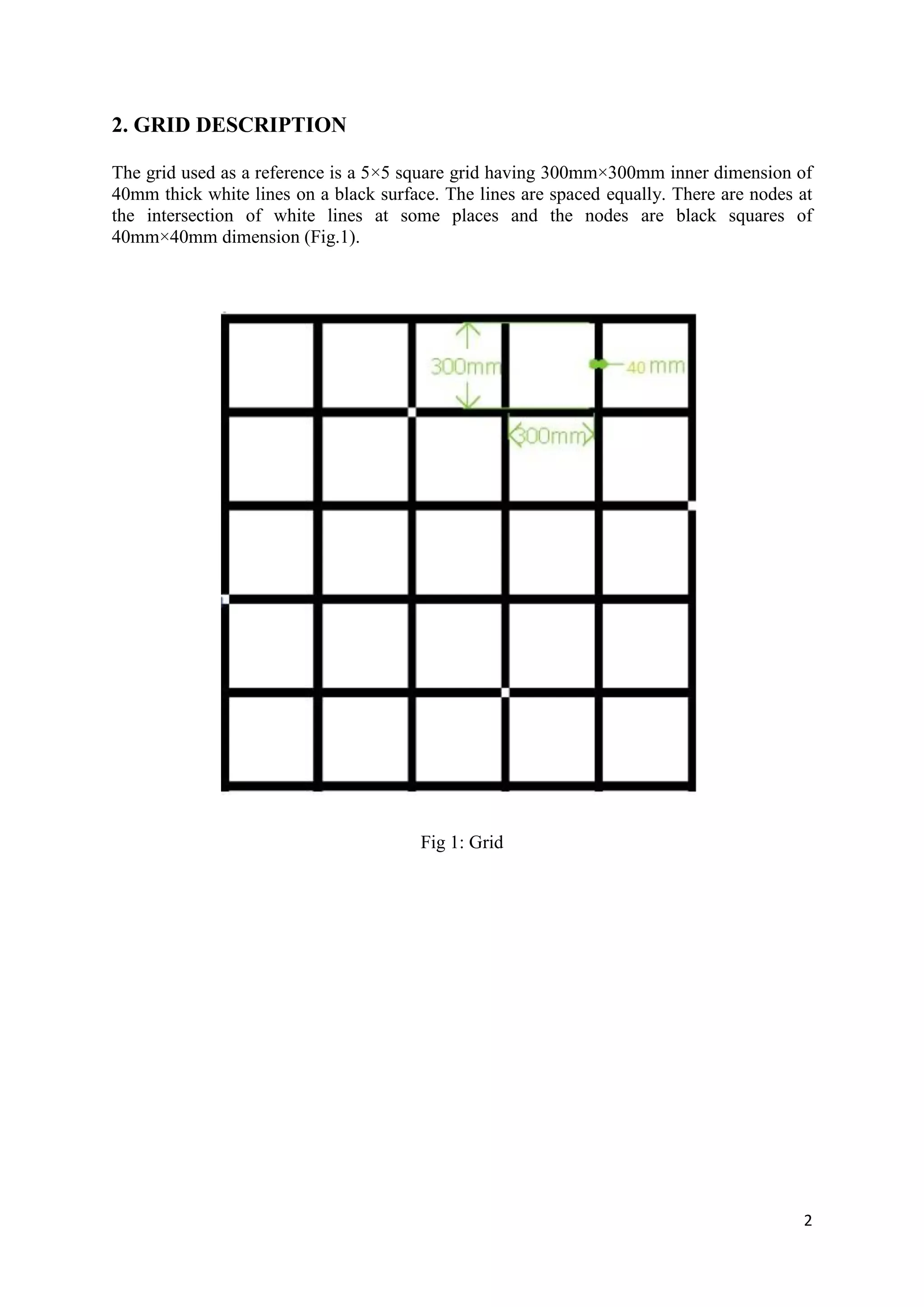
The document presents a project on a grid-based navigation system for autonomous mobile robots, focusing on path planning using the flood fill algorithm. It describes the robot's ability to localize itself, avoid specific nodes, and transfer items between locations within a structured grid environment. Various components, algorithms, and future work are outlined to enhance the robot's navigation capabilities.